


Filter by
Housing Material
Switch Starting Position
Certification
Electrical Connection
Wire Connection
DFARS Specialty Metals
Export Control Classification Number (ECCN)

About Electrical Switches
Choose a switch with the right trigger type, number of inputs, and control functions to power your equipment.
Corrosion-Resistant Washdown Foot Switches
 |  |  |
Style A | Style B | Style C |
 |  |  |
Style D | Style E | Style F |
1 Speed with Wire Leads
| |
Style A | Style B |
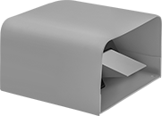
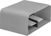
Without Guard—Switches without a guard let you easily see the pedal and step on it from many angles.
Foot Switches | Replacement Foot Switch Actuators | ||||||||||||||||
|---|---|---|---|---|---|---|---|---|---|---|---|---|---|---|---|---|---|
Wire Leads | Mounting | ||||||||||||||||
Style | No. of Circuits Controlled | Switch Starting Position | Switch Action | Switch Designation | Switching Current @ Voltage | No. of | Lg., ft. | Conduit Trade Size | Fasteners Included | No. of Holes | Hole Dia. | Each | Each | ||||
Aluminum Housing | |||||||||||||||||
| A | 1 | 1 Off | Momentary | SPST-NO | 10 amp @ 125V AC, 250V AC | 3 | 6 | 1/2 | No | 2 | 0.25" | 8225K101 | 0000000 | ——— | 0 | ||
| A | 1 | 1 Off | Momentary | SPST-NO | 18 amp @ 125V AC, 250V AC | 3 | 8 | 1/2 | No | 2 | 0.25" | 8225K51 | 000000 | 8225K511 | 000000 | ||
| A | 2 | 1 Off | Momentary | SPST-NO | 10 amp @ 125V AC, 250V AC | 4 | 8 | 1/2 | No | 2 | 0.25" | 8225K102 | 000000 | ——— | 0 | ||
| B | 2 | 1 Off | Momentary | SPST-NO | 15 amp @ 125V AC, 250V AC | 4 | 8 | 1/2 | No | 2 | 0.25" | 8225K52 | 000000 | 8225K521 | 00000 | ||
1 Speed with Quick-Disconnect Terminals
| |
Style C | Style D |
| |
Style E | Style F |
Foot Switches | Foot Switch Pedals | ||||||||||||||||
|---|---|---|---|---|---|---|---|---|---|---|---|---|---|---|---|---|---|
Mounting | |||||||||||||||||
Style | No. of Circuits Controlled | Switch Starting Position | Switch Action | Switch Designation | Switching Current @ Voltage | No. of Terminals | Quick-Disconnect Tab Wd. | Conduit Trade Size | Fasteners Included | No. of Holes | Hole Dia. | Each | Each | ||||
Aluminum Housing | |||||||||||||||||
| C | 1 | 1 Off or 1 On | Momentary | SPDT | 16 amp @ 125V AC, 250V AC | 3 | 0.187" | 1/2 | No | 4 | 0.28" | 7670K81 | 0000000 | 7670K13 | 00000 | ||
| C | 2 | 2 Off or 2 On | Momentary | DPDT | 16 amp @ 125V AC, 250V AC | 6 | 0.187" | 1/2 | No | 4 | 0.28" | 7670K82 | 000000 | 7670K13 | 0000 | ||
| D | 2 | 1 Off or 1 On | Momentary | SPDT | 16 amp @ 125V AC, 250V AC | 6 | 0.187" | 3/4 | No | 4 | 0.28" | 7670K85 | 000000 | 7670K13 | 0000 | ||
| D | 4 | 2 Off or 2 On | Momentary | DPDT | 16 amp @ 125V AC, 250V AC | 12 | 0.187" | 3/4 | No | 4 | 0.28" | 7670K86 | 000000 | 7670K13 | 0000 | ||
Aluminum Housing with Steel Guard | |||||||||||||||||
| E | 1 | 1 Off or 1 On | Momentary | SPDT | 16 amp @ 125V AC, 250V AC | 3 | 0.187" | 1/2 | No | 4 | 0.28" | 7670K83 | 000000 | 7670K13 | 0000 | ||
| E | 2 | 2 Off or 2 On | Momentary | DPDT | 16 amp @ 125V AC, 250V AC | 6 | 0.187" | 1/2 | No | 4 | 0.28" | 7670K84 | 000000 | 7670K13 | 0000 | ||
| F | 2 | 1 Off or 1 On | Momentary | SPDT | 16 amp @ 125V AC, 250V AC | 6 | 0.187" | 3/4 | No | 4 | 0.28" | 7670K87 | 000000 | 7670K13 | 0000 | ||
| F | 4 | 2 Off or 2 On | Momentary | DPDT | 16 amp @ 125V AC, 250V AC | 12 | 0.187" | 3/4 | No | 4 | 0.28" | 7670K88 | 000000 | 7670K13 | 0000 | ||
Wireless Foot Switches
1 Speed with Wire Leads
 |
Wire Leads | Mounting | ||||||||||||||||
|---|---|---|---|---|---|---|---|---|---|---|---|---|---|---|---|---|---|
No. of Circuits Controlled | Switch Starting Position | Switch Action | Switch Designation | Switching Current @ Voltage | Max. Transmission Distance, ft. | Max. Voltage | Transmission Freq., GHz | No. of | Lg., ft. | Color | Fasteners Included | No. of Holes | Hole Dia. | Each | |||
Iron Housing with Aluminum Guard | |||||||||||||||||
| 1 | 1 Off or 1 On | Momentary | SPDT | 10 amp @ 125V AC, 250V AC, 8 amp @ 24V DC | 40 | 380V AC, 48V DC | 2.41 to 2.48 | 3 | 10 | Orange | No | 3 | 0.31" | 6907T1 | 000000000 | ||
Foot Switches
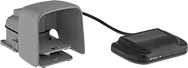
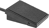 |  |
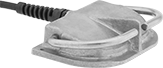
Front Pivot with 1 Pedal | Front Pivot with 1 Pedal and Three-Prong Outlet |
 |
Three-Prong Outlet |
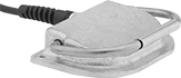
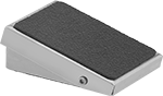
Keep your hands free for other tasks by triggering switches with your foot.
Front—Front-pivot switches reduce fatigue by letting you rest your foot on them. They won't actuate until you lean into them with your bodyweight.
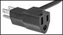
Three-Prong Outlet—Switches with a three-prong outlet allow you to plug your device directly into the switch. You can power both the switch and the device with a single wall outlet—no wiring needed.
Switch Guards—Guards (sold separately) prevent accidental switch actuation.
Foot Switches | Switch Guards | |||||||||||||||
|---|---|---|---|---|---|---|---|---|---|---|---|---|---|---|---|---|
Mounting | ||||||||||||||||
No. of Circuits Controlled | Switch Starting Position | Switch Action | Switch Designation | Switching Current @ Voltage | Housing Material | Wire Connection | No. of Terminals | Fasteners Included | No. of Holes | Hole Dia. | Each | Each | ||||
1 Speed | ||||||||||||||||
Front Pivot with 1 Pedal | ||||||||||||||||
| 1 | 1 Off | Momentary | SPST-NO | 3 amp @ 125V AC, 250V AC, 28V DC | Stainless Steel | Wire Leads | — | No | 2 | 0.12" | 9518T12 | 0000000 | 9518T21 | 0000000 | ||
| 1 | 1 Off or 1 On | Momentary | SPDT | 3 amp @ 125V AC, 250V AC, 28V DC | Stainless Steel | Butt Splice | 3 | No | 2 | 0.12" | 9518T11 | 00000 | 9518T21 | 000000 | ||
Front Pivot with 1 Pedal and Three-Prong Outlet | ||||||||||||||||
| 1 | 1 Off | Momentary | SPST-NO | 3 amp @ 125V AC | Stainless Steel | — | — | No | 2 | 0.12" | 9518T13 | 000000 | 9518T21 | 000000 | ||
Wet-Location Foot Switches
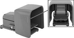 |
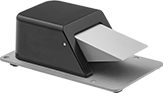
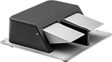
Switch with Safety Lever and Oversized Guard |
Operate these switches hands-free when working in wet or humid environments. They’re IP and NEMA rated, so they won’t corrode when exposed to water, oil, or coolant spray.
Oversized Guard—Switches with an oversized guard fit bulky shoes and toe guards.
Safety Lever—Switches with a safety lever lock the pedal in place to prevent accidental activation. Fully insert your foot to release the safety lever. If the lever isn't released, the pedal won't depress.
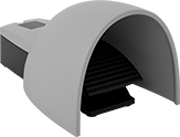
With Guard—Switches with a guard shield the pedal so you don't accidentally step on it and activate the switch.
Number of | Mounting | ||||||||||||||
|---|---|---|---|---|---|---|---|---|---|---|---|---|---|---|---|
Speeds | Circuits Controlled | Switch Starting Position | Switch Action | Switch Designation | Switching Current @ Voltage | Wire Connection | No. of Terminals | Conduit Trade Size | Fasteners Included | No. of Holes | Hole Dia. | Each | |||
Iron Housing with Safety Lever and Oversized Aluminum Guard | |||||||||||||||
IP56, NEMA 4, NEMA 13 | |||||||||||||||
| 1 | 1 | 1 Off or 1 On | Momentary | SPDT | 20 amp @ 125V AC, 250V AC, 0.5 amp @ 125V DC, 0.25 amp @ 250V DC | Screw Terminal | 3 | 3/4 | No | 3 | 0.31" | 7344K31 | 0000000 | ||
| 1 | 2 | 2 Off or 2 On | Momentary | DPDT | 20 amp @ 125V AC, 250V AC, 0.5 amp @ 125V DC, 0.25 amp @ 250V DC | Screw Terminal | 6 | 3/4 | No | 3 | 0.31" | 7344K32 | 000000 | ||
Wireless Self-Powered Foot Switches
1 Speed
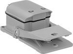
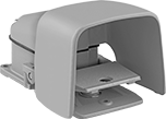
 |  |
Switch | Switch with Guard |
Actuator | ||||||||||||
|---|---|---|---|---|---|---|---|---|---|---|---|---|
No. of Circuits Controlled | Switch Action | Max. Transmission Distance, ft. | Transmission Freq., MHz | Color | Material | Color | Flammability Rating | Specs. Met | Each | |||
Powder-Coated Aluminum Housing | ||||||||||||
| 1 | Momentary | 130 | 915 | Blue | Plastic | Black | UL 94 V-0 | EN 60947-5-1 | 6399N11 | 0000000 | ||
| 1 | Momentary | 130 | 915 | Orange | Powder-Coated Aluminum | Blue | — | EN 60947-5-1 | 6399N12 | 000000 | ||
Powder-Coated Aluminum Housing with Aluminum Guard | ||||||||||||
| 1 | Momentary | 130 | 915 | Orange | Powder-Coated Aluminum | Orange | — | EN 60947-5-1 | 6399N13 | 000000 | ||
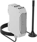 | 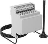 |
Screw-Terminal Wire Connection | Spring-Clamp-Terminal Wire Connection |
No. of Circuits Controlled | Switch Starting Position | No. of Terminals | Max. Transmission Distance, ft. | Transmission Freq., MHz | Switch Designation | Switching Current @ Voltage | Input Voltage | Max. Voltage, V AC | For DIN Rail Size, mm | Flammability Rating | Specs. Met | Certification | Each | |||
|---|---|---|---|---|---|---|---|---|---|---|---|---|---|---|---|---|
Screw Terminals—With LED Indicator and Antenna | ||||||||||||||||
| 4 | 4 Off | 10 | 130 | 915 | SPST-NO | 3 amp @ 250V AC, 3 amp @ 24V DC | 24V DC | 250 | 35 | UL 94 V-0 | EN 60947-5-1 | CSA-US Certified, CSA Certified | 6399N16 | 0000000 | ||
Spring-Clamp Terminals—With LED Indicator and Antenna | ||||||||||||||||
| 4 | 4 Off or 4 On | 14 | 130 | 915 | SPDT | 6 amp @ 250V AC, 2 amp @ 24V DC | 24V AC, 24V DC | 250 | 35 | — | — | CSA-US Certified, CSA Certified | 6399N17 | 000000 | ||
Variable-Speed Foot Potentiometers
 |  |
Iron Housing | Iron Housing with Aluminum Guard |
When the pedal is pressed, the built-in potentiometer adjusts the resistance to vary the speed for motor drives. These switches can be wired to either increase or decrease the current when actuated. All are rated NEMA 4 and 13 for protection from washdowns and oil/coolant spraying.
Mounting | ||||||||||||||||
|---|---|---|---|---|---|---|---|---|---|---|---|---|---|---|---|---|
No. of Circuits Controlled | Switch Starting Position | Switch Action | Switch Designation | Switching Current @ Voltage | No. of Terminals | Quick-Disconnect Tab Wd. | Conduit Trade Size | Enclosure Rating | Fasteners Included | No. of | Hole Dia. | Choose a Maximum Resistance, kohm | Each | |||
Quick-Disconnect-Terminal Wire Connection | ||||||||||||||||
Iron Housing | ||||||||||||||||
| 1 | 1 Off or 1 On | Momentary | SPDT | 15 amp @ 125V AC/250V AC | 3 | 0.187" | 3/4 | IP56, NEMA 4, NEMA 13 | No | 3 | 0.31" | 1, 5, 10 | 6817K11 | 0000000 | ||
Iron Housing with Aluminum Guard | ||||||||||||||||
| 1 | 1 Off or 1 On | Momentary | SPDT | 15 amp @ 125V AC/250V AC | 3 | 0.187" | 3/4 | IP56, NEMA 4, NEMA 13 | No | 3 | 0.31" | 1, 5, 10 | 6817K31 | 000000 | ||
