


Environment Environment | Show |
|---|
|
For Use With For Use With |
|---|
|
|
Maximum Setpoint Maximum Setpoint |
|---|
|
|
Thread Type Thread Type |
|---|
Environmental Rating Environmental Rating |
|---|
Operates On Operates On |
|---|
|
Maximum Continuous Pressure MaximumContinuous Pressure |
|---|
|
|
Connection Material Connection Material |
|---|
|
Switch Starting Position Switch Starting Position |
|---|
Housing Material Housing Material |
|---|
|
Setpoint Adjustability Setpoint Adjustability |
|---|
|
Connection Style Connection Style |
|---|
|
Scale Scale |
|---|
|
For Conduit Trade Size For Conduit Trade Size |
|---|
|
Gasket Material Gasket Material |
|---|
|
Adjustment Type Adjustment Type |
|---|
|
Maximum Switching Current Maximum Switching Current |
|---|
|
DFARS (Defense Acquisition Regulations Supplement) DFARS (Defense AcquisitionRegulations Supplement) |
|---|
System of Measurement System of Measurement |
|---|
|
RoHS (Restriction of Hazardous Substances) RoHS (Restriction ofHazardous Substances) |
|---|
|
About Pressure Switches
More
Hazardous Location Pressure Switches
Built with an explosionproof enclosure to meet NEMA 7 and 9 standards for hazardous locations, these switches were tested and verified by UL and CSA for use where explosive liquids, dust, and gas are present. When they reach the set pressure, they power equipment, signal controls, or trigger alarms. They’re single pole, double throw (SPDT) and can be installed to turn one circuit from off to on (normally open) or from on to off (normally closed). In addition to being UL listed and CSA certified, these switches are CE marked, so they also meet European safety standards.
All switches are IP and NEMA rated for use outdoors and protection from some corrosion, dust, and spraying water.
IP67 and NEMA 4X rated switches seal out water from temporary submersion and have increased protection against corrosion, similar to 304 stainless steel.
| Setpoint, psi | Approximate Difference Between Setpoint and Reset Point, psi | Max. Continuous Pressure, psi | Accuracy | Max. Switching Current | Connection Material | For Use With | Environmental Rating | Each | ||
Wire Leads | ||||||||||
|---|---|---|---|---|---|---|---|---|---|---|
1/4 NPT Male Pipe Connection | ||||||||||
| A | 8-60 | 5 | 60 | ±5% | 5 A @ 125 V AC 5 A @ 250 V AC | 316 Stainless Steel | Air, Diesel Fuel, Gasoline, Hydraulic Fluid, Natural Gas, Water | NEC Class I Division 1 Groups A, B, C, D NEC Class II Division 1 Groups E, F ,G IP67 NEMA 4X NEMA 7 NEMA 9 | 00000000 | 0000000 |
| A | 10-100 | 9 | 100 | ±5% | 5 A @ 125 V AC 5 A @ 250 V AC | 316 Stainless Steel | Air, Diesel Fuel, Gasoline, Hydraulic Fluid, Natural Gas, Water | NEC Class I Division 1 Groups A, B, C, D NEC Class II Division 1 Groups E, F ,G IP67 NEMA 4X NEMA 7 NEMA 9 | 00000000 | 000000 |
| A | 20-200 | 16 | 200 | ±2% | 5 A @ 125 V AC 5 A @ 250 V AC | 316 Stainless Steel | Air, Diesel Fuel, Gasoline, Hydraulic Fluid, Natural Gas, Water | NEC Class I Division 1 Groups A, B, C, D NEC Class II Division 1 Groups E, F ,G IP67 NEMA 4X NEMA 7 NEMA 9 | 00000000 | 000000 |
| A | 50-500 | 60 | 500 | ±2% | 5 A @ 125 V AC 5 A @ 250 V AC | 316 Stainless Steel | Air, Diesel Fuel, Gasoline, Hydraulic Fluid, Natural Gas, Water | NEC Class I Division 1 Groups A, B, C, D NEC Class II Division 1 Groups E, F ,G IP67 NEMA 4X NEMA 7 NEMA 9 | 00000000 | 000000 |
| A | 100-1,000 | 87 | 1,000 | ±2% | 5 A @ 125 V AC 5 A @ 250 V AC | 316 Stainless Steel | Air, Diesel Fuel, Gasoline, Hydraulic Fluid, Natural Gas, Water | NEC Class I Division 1 Groups A, B, C, D NEC Class II Division 1 Groups E, F ,G IP67 NEMA 4X NEMA 7 NEMA 9 | 00000000 | 000000 |
| A | 200-2,000 | 165 | 2,000 | ±2% | 5 A @ 125 V AC 5 A @ 250 V AC | 316 Stainless Steel | Air, Diesel Fuel, Gasoline, Hydraulic Fluid, Natural Gas, Water | NEC Class I Division 1 Groups A, B, C, D NEC Class II Division 1 Groups E, F ,G IP67 NEMA 4X NEMA 7 NEMA 9 | 00000000 | 000000 |
1/2 NPT Female Pipe Connection | ||||||||||
| B | 6-30 | 2 | 30 | ±1% | 5 A @ 125 V AC 5 A @ 250 V AC | 316 Stainless Steel | Air, Diesel Fuel, Gasoline, Hydraulic Fluid, Natural Gas, Water | NEC Class I Divisions 1, 2 Groups A, B, C, D NEC Class II Divisions 1, 2 Groups E, F, G IP66 NEMA 4 NEMA 7 NEMA 9 | 00000000 | 000000 |
| B | 12-60 | 2 | 60 | ±1% | 5 A @ 125 V AC 5 A @ 250 V AC | 316 Stainless Steel | Air, Diesel Fuel, Gasoline, Hydraulic Fluid, Natural Gas, Water | NEC Class I Divisions 1, 2 Groups A, B, C, D NEC Class II Divisions 1, 2 Groups E, F, G IP66 NEMA 4 NEMA 7 NEMA 9 | 00000000 | 000000 |
| B | 20-100 | 3.5 | 100 | ±1% | 5 A @ 125 V AC 5 A @ 250 V AC | 316 Stainless Steel | Air, Diesel Fuel, Gasoline, Hydraulic Fluid, Natural Gas, Water | NEC Class I Divisions 1, 2 Groups A, B, C, D NEC Class II Divisions 1, 2 Groups E, F, G IP66 NEMA 4 NEMA 7 NEMA 9 | 00000000 | 000000 |
| B | 40-200 | 6.5 | 200 | ±1% | 5 A @ 125 V AC 5 A @ 250 V AC | 316 Stainless Steel | Air, Diesel Fuel, Gasoline, Hydraulic Fluid, Natural Gas, Water | NEC Class I Divisions 1, 2 Groups A, B, C, D NEC Class II Division 1 Groups E, F ,G IP66 NEMA 4 NEMA 7 NEMA 9 | 00000000 | 000000 |
| B | 80-400 | 11 | 400 | ±1% | 5 A @ 125 V AC 5 A @ 250 V AC | 316 Stainless Steel | Air, Diesel Fuel, Gasoline, Hydraulic Fluid, Natural Gas, Water | NEC Class I Divisions 1, 2 Groups A, B, C, D NEC Class II Divisions 1, 2 Groups E, F, G IP66 NEMA 4 NEMA 7 NEMA 9 | 00000000 | 000000 |
Washdown Differential Pressure Switches with Dial Indicator
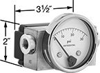
- For Use With: Air, Hydraulic Fluid, Water
- Connection Material: Brass
- Connection: NPT Female
- Switching Current: 0.25A
- Switching Voltage: 120V AC
Not only are these switches rated NEMA 4X for protection from dirt, washdowns, and corrosion, they also have an indicator for additional monitoring at the source of your application. Switches operate based on the difference in pressure between two process lines. When the differential pressure exceeds your setpoint, the switch is activated. Use them to automate controls or activate an alarm in your process. Switches are single pole, double throw (SPDT), so they switch one circuit on or off. They can be wired normally open (NO) or normally closed (NC).
Temperature Range, °F | Conduit | Lens | |||||||||||
|---|---|---|---|---|---|---|---|---|---|---|---|---|---|
| Setpoint, psi | Approximate Difference Between Setpoint and Reset Point, psi | Max. Pressure, psi | Accuracy | Pipe Size | Environment | Process | For Trade Size | Connection | Dia. | Material | Specifications Met | Each | |
Brass Housing | |||||||||||||
| 3-15 | 3 | 5,000 | ±2% | 1/4 | -40° to 175° | -40° to 175° | 1/2 | NPT Female | 3" | Glass | CSA Certified | 00000000 | 0000000 |
| 6-30 | 6 | 5,000 | ±2% | 1/4 | -40° to 175° | -40° to 175° | 1/2 | NPT Female | 3" | Glass | CSA Certified | 00000000 | 000000 |
| 10-50 | 10 | 5,000 | ±2% | 1/4 | -40° to 175° | -40° to 175° | 1/2 | NPT Female | 3" | Glass | CSA Certified | 00000000 | 000000 |
Hazardous Location Flow Switches for Water, Air, and Inert Gas
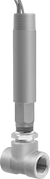
These switches are UL listed for environments with flammable gases and combustible dust. They activate or deactivate equipment when the flow rate reaches your set point. All are single pole, double throw (SPDT) and can be installed to turn one circuit from “off” to “on” (normally open) or from “on” to “off” (normally closed).
Switches with a brass body meet NEC Class I, Divisions 1 and 2, Groups B, C, and D; and NEC Class II, Divisions 1 and 2, Groups E, F, and G.
Switches with a 304 stainless steel body are more corrosion resistant than switches with a brass body and meet NEC Class I, Divisions 1 and 2, Groups A, B, C, and D; and NEC Class II, Divisions 1 and 2, Groups E, F, and G.
![]() For technical drawings and 3-D models, click on a part number.
For technical drawings and 3-D models, click on a part number.
Set Point | Conduit | |||||||||||||
|---|---|---|---|---|---|---|---|---|---|---|---|---|---|---|
| Pipe Size | Thread Type | Gender | For Water, gpm | For Air and Inert Gas, scfm | Max. Pressure | Temp. Range, °F | Voltage | Current | Trade Size | Thread Type | Gender | End-to-End Lg. | Each | |
Brass Body | ||||||||||||||
| 1/2 | NPT | Female | 1.5 | 6.5 | 250 psi @ 70° F | -4° to 220° | 120V AC/ 240V AC | 5 A @ 120 V AC | 3/4 | NPT | Male | 2 1/4" | 00000000 | 0000000 |
| 3/4 | NPT | Female | 2 | 10 | 250 psi @ 70° F | -4° to 220° | 120V AC/ 240V AC | 5 A @ 120 V AC | 3/4 | NPT | Male | 2 3/8" | 00000000 | 000000 |
| 1 | NPT | Female | 3 | 14 | 250 psi @ 70° F | -4° to 220° | 120V AC/ 240V AC | 5 A @ 120 V AC | 3/4 | NPT | Male | 2 1/2" | 00000000 | 000000 |
| 1 1/4 | NPT | Female | 4 | 21 | 250 psi @ 70° F | -4° to 220° | 120V AC/ 240V AC | 5 A @ 120 V AC | 3/4 | NPT | Male | 2 5/8" | 00000000 | 000000 |
| 1 1/2 | NPT | Female | 6 | 33 | 250 psi @ 70° F | -4° to 220° | 120V AC/ 240V AC | 5 A @ 120 V AC | 3/4 | NPT | Male | 2 7/8" | 00000000 | 000000 |
| 2 | NPT | Female | 10 | 43 | 250 psi @ 70° F | -4° to 220° | 120V AC/ 240V AC | 5 A @ 120 V AC | 3/4 | NPT | Male | 3" | 00000000 | 000000 |
304 Stainless Steel Body | ||||||||||||||
| 1/2 | NPT | Female | 1.5 | 6.5 | 2000 psi @ 70° F | -4° to 220° | 120V AC/ 240V AC | 5 A @ 120 V AC | 3/4 | NPT | Male | 2 1/4" | 00000000 | 000000 |
| 3/4 | NPT | Female | 2 | 10 | 2000 psi @ 70° F | -4° to 220° | 120V AC/ 240V AC | 5 A @ 120 V AC | 3/4 | NPT | Male | 2 5/8" | 00000000 | 000000 |
| 1 | NPT | Female | 3 | 14 | 2000 psi @ 70° F | -4° to 220° | 120V AC/ 240V AC | 5 A @ 120 V AC | 3/4 | NPT | Male | 3" | 00000000 | 000000 |
| 2 | NPT | Female | 10 | 43 | 2000 psi @ 70° F | -4° to 220° | 120V AC/ 240V AC | 5 A @ 120 V AC | 3/4 | NPT | Male | 4 3/4" | 00000000 | 00000000 |
Adjustable Hazardous Location Flow Switches for Water, Air, and Inert Gas
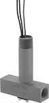
For applications with a variable flow rate in environments with flammable gases and combustible dust, these UL-listed switches have an adjustment screw to alter the set point. They activate or deactivate equipment when the flow rate reaches your set point. All are single pole, double throw (SPDT) and can be installed to turn one circuit from “off” to “on” (normally open) or from “on” to “off” (normally closed).
Switch with a brass body meets NEC Class I, Divisions 1 and 2, Groups B, C, and D; and NEC Class II, Divisions 1 and 2, Groups E, F, and G.
Switch with a 304 stainless steel body is more corrosion resistant than the switch with a brass body. It meets NEC Class I, Divisions 1 and 2, Groups A, B, C, and D; and NEC Class II, Divisions 1 and 2, Groups E, F, and G.
![]() For technical drawings and 3-D models, click on a part number.
For technical drawings and 3-D models, click on a part number.
Set Point | Conduit | |||||||||||||
|---|---|---|---|---|---|---|---|---|---|---|---|---|---|---|
| Pipe Size | Thread Type | Gender | For Water, gpm | For Air and Inert Gas, scfm | Max. Pressure | Temp. Range, °F | Voltage | Current | Trade Size | Thread Type | Gender | End-to-End Lg. | Each | |
Brass Body | ||||||||||||||
| 1/2 | NPT | Female | 0.04 to 0.75 | 0.18 to 2.7 | 1450 psi @ 70° F | -4° to 220° | 120V AC/ 240V AC | 5 A @ 120 V AC | 3/4 | NPT | Male | 3 5/8" | 00000000 | 0000000 |
304 Stainless Steel Body | ||||||||||||||
| 1/2 | NPT | Female | 0.04 to 0.75 | 0.18 to 2.7 | 1450 psi @ 70° F | -4° to 220° | 120V AC/ 240V AC | 5 A @ 120 V AC | 3/4 | NPT | Male | 3 5/8" | 00000000 | 000000 |
Hazardous Location Insertion Flow Switches for Water, Oil, Air, and Inert Gas
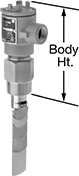
For installation in environments with flammable gases and combustible dust, these flow switches are UL listed for hazardous locations. They meet NEC Class I, Divisions 1 and 2, Groups C and D; and NEC Class II, Divisions 1 and 2, Groups E, F, and G. They’re installed in tees or pipe outlets to detect the flow rate of liquid in contact with the sensing paddle. Switches activate or deactivate equipment when the flow rate reaches your set point. All come with five sensing paddles that can be trimmed to fit a range of pipe sizes. The flow rate varies based on the pipe size and paddle used.
SPDT switches control one circuit. They can be installed to turn the circuit from “off” to “on” (normally open) or from “on” to “off” (normally closed).
DPDT switches control two circuits. They can be installed to turn both circuits from “off” to “on” (normally open) or from “on” to “off” (normally closed).
Switches with a 316 stainless steel body are more corrosion resistant than switches with a brass body.
![]() For technical drawings and 3-D models, click on a part number.
For technical drawings and 3-D models, click on a part number.
Set Point | Conduit | ||||||||||||||
|---|---|---|---|---|---|---|---|---|---|---|---|---|---|---|---|
| Pipe Size | Thread Type | Gender | For Pipe Size | For Water and Oil, gpm | For Air and Inert Gas, scfm | Max. Pressure | Temp. Range, °F | Voltage | Current | Trade Size | Thread Type | Gender | Body Ht. | Each | |
SPDT | |||||||||||||||
Brass Body | |||||||||||||||
| 1 1/2 | NPT | Male | 1 1/2 to 20 | 3 to 2,400 | 17 to 10,000 | 1000 psi @ 70° F | -4° to 275° | 120V AC 240V AC | 10 A @ 120 V AC | 3/4 | NPT | Female | 8" | 00000000 | 0000000 |
316 Stainless Steel Body | |||||||||||||||
| 1 1/2 | NPT | Male | 1 1/2 to 20 | 3 to 2,400 | 17 to 10,000 | 2000 psi @ 70° F | -4° to 275° | 120V AC 240V AC | 10 A @ 120 V AC | 3/4 | NPT | Female | 8" | 00000000 | 000000 |
DPDT | |||||||||||||||
Brass Body | |||||||||||||||
| 1 1/2 | NPT | Male | 1 1/2 to 20 | 3 to 2,400 | 17 to 10,000 | 1000 psi @ 70° F | -4° to 275° | 120V AC 240V AC | 10 A @ 120 V AC | 3/4 | NPT | Female | 8" | 00000000 | 000000 |
316 Stainless Steel Body | |||||||||||||||
| 1 1/2 | NPT | Male | 1 1/2 to 20 | 3 to 2,400 | 17 to 10,000 | 2000 psi @ 70° F | -4° to 275° | 120V AC 240V AC | 10 A @ 120 V AC | 3/4 | NPT | Female | 8" | 00000000 | 000000 |