


Thread Size Thread Size | Show |
|---|
Thread Size Thread Size | Hide |
|---|

Thread Type Thread Type |
|---|

For Thread Direction For Thread Direction |
|---|
|
Thread Spacing Thread Spacing |
|---|
Material Material |
|---|
|
Specifications Met Specifications Met |
|---|
|
For Maximum Hole Diameter For Maximum Hole Diameter |
|---|
|
For Helical Insert Style For Helical Insert Style |
|---|
|
Drill Bit Size Drill Bit Size |
|---|
|
For Tap Type For Tap Type |
|---|
|
RoHS (Restriction of Hazardous Substances) RoHS (Restriction ofHazardous Substances) |
|---|
|
For Minimum Material Thickness For MinimumMaterial Thickness |
|---|
|
Passivation Passivation |
|---|
|
Tensile Strength Tensile Strength |
|---|
|
Helical Insert Style Helical Insert Style |
|---|
|
Thread Direction Thread Direction |
|---|
 | |
DFARS (Defense Acquisition Regulations Supplement) DFARS (Defense AcquisitionRegulations Supplement) |
|---|
Number of Inserts Included Number of Inserts Included |
|---|
|
REACH (Registration, Evaluation, Authorization and Restriction of Chemicals) REACH (Registration,Evaluation, Authorization and Restriction of Chemicals) |
|---|
|
How to Install Helical Inserts
More
About Helical Insert Length
More
Stainless Steel Helical Inserts
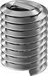
Also known as Heli-Coil inserts, these inserts have coils that expand once installed to securely anchor the insert. All have a prong for ease of installation. An installation tool grips the prong and reduces the coil diameter, enabling the insert to fit in tapped holes. Remove the prong to insert the screw. Installation requires a drill bit, a helical insert tap, an installation tool, and a prong break-off tool.
Inserts that meet DIN 8140 adhere to international standards for dimensions.
![]() For technical drawings and 3-D models, click on a part number.
For technical drawings and 3-D models, click on a part number.
Inserts | Through-Hole Taps | Closed-End Hole Taps | Installation Tools | ||||||||||||
|---|---|---|---|---|---|---|---|---|---|---|---|---|---|---|---|
| Thread Size | Thread Pitch, mm | Thread Spacing | Installed Lg., mm | Drill Bit Size | For Max. Hole Dia. | Specifications Met | Pkg. Qty. | Pkg. | Each | Each | Each | ||||
18-8 Stainless Steel—Right-Hand Threaded | |||||||||||||||
| M20 | 2.5 | Coarse | 20 | 13/16" | 13/16" | DIN 8140, SAE MA3279-124 | 1 | 000000000 | 00000 | 000000000 | 0000000 | 000000000 | 0000000 | 000000000 | 0000000 |
| M20 | 2.5 | Coarse | 30 | 13/16" | 13/16" | DIN 8140, SAE MA3279-174 | 1 | 000000000 | 0000 | 000000000 | 000000 | 000000000 | 000000 | 000000000 | 000000 |
| M20 | 1.5 | Extra Fine | 30 | 13/16" | 13/16" | SAE MA3279-172 | 1 | 000000000 | 0000 | 000000000 | 000000 | 000000000 | 000000 | 000000000 | 000000 |
Stainless Steel Screw-Locking Helical Inserts
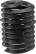
A distorted thread grips the screw to resist loosening. Also known as Heli-Coil inserts, these inserts have coils that expand once installed to securely anchor the insert. All have a prong for ease of installation. An installation tool grips the prong and reduces the coil diameter, enabling the insert to fit in tapped holes. Remove the prong to insert the screw. Installation requires a drill bit, a helical insert tap, an installation tool, and a prong break-off tool.
![]() For technical drawings and 3-D models, click on a part number.
For technical drawings and 3-D models, click on a part number.
Inserts | Through-Hole Taps | Closed-End Hole Taps | Installation Tools | ||||||||||||
|---|---|---|---|---|---|---|---|---|---|---|---|---|---|---|---|
| Thread Size | Thread Pitch, mm | Thread Spacing | Installed Lg., mm | Drill Bit Size | For Max. Hole Dia. | Specifications Met | Pkg. Qty. | Pkg. | Each | Each | Each | ||||
18-8 Stainless Steel | |||||||||||||||
| M20 | 2.5 | Coarse | 20 | 13/16" | 13/16" | SAE MA3329-124 | 1 | 000000000 | 00000 | 000000000 | 0000000 | 000000000 | 0000000 | 000000000 | 0000000 |
| M20 | 2.5 | Coarse | 30 | 13/16" | 13/16" | SAE MA3329-174 | 1 | 000000000 | 0000 | 000000000 | 000000 | 000000000 | 000000 | 000000000 | 000000 |
Helical Inserts with Installation Tools
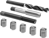
Inserts come with a through-hole tap and installation tool. Also known as Heli-Coil inserts, they have coils that expand once installed to securely anchor the insert. All have a prong for ease of installation. An installation tool grips the prong and reduces the coil diameter, enabling the insert to fit in tapped holes. Remove the prong to insert the screw.
| Thread Size | Thread Pitch, mm | Thread Spacing | Installed Lg., mm | Drill Bit Size | For Max. Hole Dia. | No. of Inserts Included | Includes | Each | |
18-8 Stainless Steel—Right-Hand Threaded | |||||||||
|---|---|---|---|---|---|---|---|---|---|
| M20 | 2.5 | Coarse | 30 | 13/16" | 13/16" | 4 | Drill Bit, Through-Hole Tap, Installation Tool | 000000000 | 0000000 |
Installation Tools for Helical Inserts
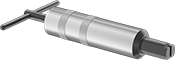
Screw an insert onto these tools and drive them a quarter to half-turn below the material’s surface. They’re compatible with helical inserts that have a prong.
![]() For technical drawings and 3-D models, click on a part number.
For technical drawings and 3-D models, click on a part number.
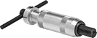
Extraction Tools for Helical Inserts
Place the tip of these tools into an insert and strike a light blow to the tool’s head. Then turn the tools counterclockwise with pressure to extract the insert.
| For Thread Size | Each | |
| 7/16"-14, 7/16"-20, 1/2"-13, 1/2"-20, 1/2"-28, 9/16"-12, 9/16"-18, 5/8"-11, 5/8"-18, 5/8"-24, 3/4"-10, 3/4"-16, 3/4"-20, 7/8"-9, 7/8"-14, 7/8"-20, 1"-8, 1"-12, 1"-14, M12, M14, M16, M18, M20, M22, M24 | 000000000 | 000000 |