


For Use With For Use With | Show |
|---|
|
For Use With For Use With | Hide |
|---|
|
Maximum Outlet Pressure Maximum Outlet Pressure |
|---|
|
|
Maximum Outlet Pressure Gauge Maximum OutletPressure Gauge |
|---|
|
|
Inlet Thread Direction Inlet Thread Direction |
|---|
|
Body Material Body Material |
|---|
|
Outlet Thread Type Outlet Thread Type |
|---|
|
Diaphragm Material Diaphragm Material |
|---|
|
Inlet Pressure Gauge Included Inlet Pressure Gauge Included |
|---|
|
REACH (Registration, Evaluation, Authorization and Restriction of Chemicals) REACH (Registration,Evaluation, Authorization and Restriction of Chemicals) |
|---|
|
RoHS (Restriction of Hazardous Substances) RoHS (Restriction ofHazardous Substances) |
|---|
|
About Gas Regulators
More
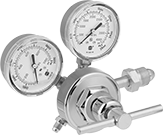
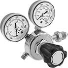
Tank-Mount Pressure-Regulating Valves for Air and Inert Gas
- For Use With: See Table
- Temperature Range: -20° to 120° F
These valves automatically reduce a high inlet pressure from compressed gas tanks to a lower, stable outlet pressure. All have Compressed Gas Association (CGA) numbered inlet fittings for secure connections to compressed gas tanks. Choose a valve with the same CGA number as your tank and other system components. Valves have a gauge to monitor outlet pressure and a gauge to monitor inlet pressure from the tank.
Choose a valve with a maximum outlet pressure that’s approximately twice your application’s normal operating pressure. Your operating pressure should never exceed 75% of the valve’s maximum outlet pressure.
Single-stage valves reduce pressure in one step, which causes the outlet pressure to fluctuate slightly as you empty the tank. They’re best for applications where a constant outlet pressure isn’t critical.
Two-stage valves progressively reduce pressure over two steps for more consistent outlet pressure at all times. They’re often used in applications that require a constant outlet pressure regardless of the tank level.
Valves with a brass body have a longer service life than valves with a brass and steel body.
Valves with a stainless steel diaphragm can withstand harsh environments.
Valves with flared tube outlet fittings form a tight seal on metal tubing.
Inlet | Outlet | Material | ||||||||||
|---|---|---|---|---|---|---|---|---|---|---|---|---|
| CGA Number | Location | Thread Direction | Pressure Gauge Range, psi | Location | Thread Direction | Pressure Range, psi | Pressure Adjustment Method | Body | Seal | Diaphragm | Each | |
For Use With Argon, Helium, and Nitrogen | ||||||||||||
37° Flared UNF Male Outlet × NGO Male Inlet | ||||||||||||
| CGA 580 | Side | Right Hand | 0 to 4,000 | Side | Right Hand | 10 to 200 | T-Handle | Brass | Polyurethane | Neoprene/Nylon | 00000000 | 0000000 |
45° Flared UN/UNF (SAE 45°) Male Outlet × NGO Male Inlet | ||||||||||||
| CGA 580 | Side | Right Hand | 0 to 4,000 | Side | Right Hand | 0 to 250 | T-Handle | Brass | PTFE | Neoprene | 00000000 | 000000 |
| CGA 580 | Side | Right Hand | 0 to 4,000 | Side | Right Hand | 0 to 500 | T-Handle | Brass | PTFE | Neoprene | 00000000 | 000000 |
5/8"-18 UNF Female Outlet × NGO Male Inlet | ||||||||||||
| CGA 580 | Side | Right Hand | 0 to 4,000 | Side | Right Hand | 0 to 125 | T-Handle | Brass | PTFE | Stainless Steel | 00000000 | 000000 |
| CGA 580 | Side | Right Hand | 0 to 4,568 | Side | Right Hand | 5 to 150 | Knob | Brass | Polyester/Polyurethane | Neoprene/Nylon | 00000000 | 000000 |
9/16"-18 UNF Male Outlet × NGO Male Inlet | ||||||||||||
| CGA 580 | Side | Right Hand | 0 to 4,000 | Side | Right Hand | 0 to 50 | T-Handle | Brass | PTFE | Neoprene | 00000000 | 000000 |
| CGA 580 | Side | Right Hand | 0 to 4,000 | Side | Right Hand | 0 to 125 | T-Handle | Brass | PTFE | Rubber | 0000000 | 000000 |
| CGA 580 | Side | Right Hand | 0 to 4,000 | Side | Right Hand | 0 to 145 | Knob | Brass/Steel | PTFE | Rubber | 0000000 | 000000 |
| CGA 580 | Side | Right Hand | 0 to 4,000 | Side | Right Hand | 0 to 200 | T-Handle | Brass | PTFE | Rubber | 0000000 | 000000 |
Inlet | Outlet | Material | ||||||||||
|---|---|---|---|---|---|---|---|---|---|---|---|---|
| CGA Number | Location | Thread Direction | Pressure Gauge Range, psi | Location | Thread Direction | Pressure Range, psi | Pressure Adjustment Method | Body | Seal | Diaphragm | Each | |
For Use With Argon, Helium, and Nitrogen | ||||||||||||
1/4 NPT Female Outlet × NGO Male Inlet | ||||||||||||
| CGA 580 | Side | Right Hand | 0 to 4,000 | Side | Right Hand | 0 to 250 | T-Handle | Brass | PTFE | Neoprene | 00000000 | 0000000 |
| CGA 580 | Side | Right Hand | 0 to 4,000 | Side | Right Hand | 0 to 250 | T-Handle | Brass | PTFE | Stainless Steel | 00000000 | 000000 |
5/8"-18 UNF Female Outlet × NGO Male Inlet | ||||||||||||
| CGA 580 | Side | Right Hand | 0 to 4,000 | Side | Right Hand | 0 to 50 | T-Handle | Brass | PTFE | Neoprene | 00000000 | 000000 |
| CGA 580 | Side | Right Hand | 0 to 4,000 | Side | Right Hand | 0 to 50 | T-Handle | Brass | PTFE | Stainless Steel | 0000000 | 000000 |
| CGA 580 | Side | Right Hand | 0 to 4,000 | Side | Right Hand | 0 to 125 | T-Handle | Brass | PTFE | Stainless Steel | 0000000 | 000000 |
| CGA 580 | Side | Right Hand | 0 to 4,000 | Side | Right Hand | 0 to 125 | T-Handle | Brass/Steel | PTFE | Rubber | 0000000 | 000000 |
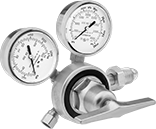
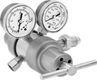
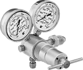
Tank-Mount High-Pressure-Regulating Valves for Air and Inert Gas
- For Use With: See Table
- Temperature Range: -20° to 120° F
Often used for pressure-vessel testing and other high-pressure applications, these valves can handle at least seven times the outlet pressure of standard tank-mount pressure-regulating valves. They automatically reduce a high inlet pressure from compressed gas tanks to a lower, stable outlet pressure. All have Compressed Gas Association (CGA) numbered inlet fittings for secure connections to compressed gas tanks. Choose a valve with the same CGA number as your tank and other system components. Outlet fittings are Swagelok® for a leak-free seal around hard metal tubing in high-pressure lines. Also known as instrumentation fittings, Swagelok® fittings are compatible with Parker A-Lok, Gyrolok, Bilok, and Tylok fittings. Valves have a gauge to monitor outlet pressure and a gauge to monitor inlet pressure from the tank. They are single stage and reduce pressure in one step, which causes the outlet pressure to fluctuate slightly as you empty the tank.
Choose a valve with a maximum outlet pressure that’s approximately twice your application’s normal operating pressure. Your operating pressure should never exceed 75% of the valve’s maximum outlet pressure.
Inlet | Outlet | Material | |||||||||||
|---|---|---|---|---|---|---|---|---|---|---|---|---|---|
| CGA Number | Location | Thread Direction | Pressure Gauge Range, psi | Stage | For Tube OD | Location | Pressure Range, psi | Pressure Adjustment Method | Shape | Body | Seal | Each | |
NGO Female Inlet × Swagelok® Female Outlet | |||||||||||||
| CGA 677 | Side | Left Hand | 0 to 7,500 | Single | 1/4" | Bottom | 300 to 4,500 | T-Handle | 90° Elbow | Brass | PCTFE | 0000000 | 000000000 |
NGO Male Inlet × Swagelok® Female Outlet | |||||||||||||
| CGA 580 | Side | Right Hand | 0 to 4,000 | Single | 1/4" | Bottom | 100 to 1,500 | T-Handle | 90° Elbow | Brass | PCTFE | 0000000 | 000000 |
| CGA 580 | Side | Right Hand | 0 to 4,000 | Single | 1/4" | Bottom | 200 to 3,000 | T-Handle | 90° Elbow | Brass | PCTFE | 0000000 | 000000 |
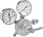
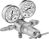
Easy-Read Tank-Mount Pressure-Regulating Valves with Flowmeter for Inert Gas
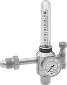
- For Use With: See Table
Flowmeters let you see the gas flow rate from a distance. These valves automatically reduce a high inlet pressure from compressed gas tanks to a lower, stable outlet pressure. All have Compressed Gas Association (CGA) numbered inlet fittings for secure connections to compressed gas tanks. Choose a valve with the same CGA number as your tank and other system components. They have a gauge for monitoring inlet pressure from the tank.
Single-stage valves reduce pressure in one step, which causes the outlet pressure to fluctuate slightly as you empty the tank. They’re best for applications where a constant outlet pressure isn’t critical.
Two-stage valves progressively reduce pressure over two steps for more consistent outlet pressure at all times. They’re often used in applications that require a constant outlet pressure regardless of the tank level.
Valves with one flowmeter are for one piece of equipment on a tank. The flowmeter has a single scale.
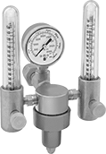
Valve with two flowmeters lets you simultaneously run two pieces of equipment from one tank. Both flowmeters have a dual scale.
Adapters (sold separately) change 5/8"-18 outlets to 9/16"-18 male connections, and vice versa.
Inlet | Outlet | Material | ||||||||||||
|---|---|---|---|---|---|---|---|---|---|---|---|---|---|---|
| CGA Number | Location | Thread Direction | Pressure Gauge Range, psi | Stage | Thread Size | Location | Thread Direction | Flow Range, scfh | Number of Flowmeters | Body | Seal | Diaphragm | Each | |
UNF Female Outlet × NGO Male Inlet | ||||||||||||||
| CGA 580 | Side | Right Hand | 0 to 3,000 | Two | 5/8"-18 | Side | Right Hand | 0 to 18 (Argon), 0 to 50 (Helium) | 1 | Brass | PTFE | Neoprene | 000000000 | 0000000 |
| CGA 580 | Side | Right Hand | 0 to 3,000 | Two | 5/8"-18 | Side | Right Hand | 0 to 65 (Argon), 0 to 200 (Helium) | 1 | Brass | PTFE | Neoprene | 000000000 | 000000 |
| CGA 580 | Side | Right Hand | 0 to 4,000 | Single | 5/8"-18 | Side | Right Hand | 0 to 45 (Argon), 0 to 140 (Helium) | 1 | Brass | PTFE | Neoprene | 00000000 | 000000 |
| CGA 580 | Side | Right Hand | 0 to 4,000 | Single | 5/8"-18 | Side | Right Hand | 0 to 45 (Argon), 0 to 140 (Helium) | 2 | Brass | PTFE | Neoprene | 0000000 | 000000 |
| Optional Adapter | 00000000 | Each | 000000 |
Inlet | Outlet | Material | ||||||||||||
|---|---|---|---|---|---|---|---|---|---|---|---|---|---|---|
| CGA Number | Location | Thread Direction | Pressure Gauge Range, psi | Stage | Thread Size | Location | Thread Direction | Flow Range, scfh | Number of Flowmeters | Body | Seal | Diaphragm | Each | |
UNF Female Outlet × NGO Male Inlet | ||||||||||||||
| CGA 580 | Side | Right Hand | 0 to 3,000 | Single | 5/8"-18 | Side | Right Hand | 0 to 40 (Argon), 0 to 40 (Argon/Carbon Dioxide Blend), 0 to 150 (Helium) to150 | 1 | Brass | PTFE | Neoprene | 000000000 | 0000000 |
| CGA 580 | Side | Right Hand | 0 to 3,000 | Two | 5/8"-18 | Side | Right Hand | 0 to 40 (Argon), 0 to 40 (Argon/Carbon Dioxide Blend), 0 to 150 (Helium) to150 | 1 | Brass | PTFE | Neoprene | 000000000 | 000000 |
| Optional Adapter | 00000000 | Each | 000000 |
Inlet | Outlet | Material | ||||||||||||
|---|---|---|---|---|---|---|---|---|---|---|---|---|---|---|
| CGA Number | Location | Thread Direction | Pressure Gauge Range, psi | Stage | Thread Size | Location | Thread Direction | Flow Range, scfh | Number of Flowmeters | Body | Seal | Diaphragm | Each | |
UNF Female Outlet × NGO Male Inlet | ||||||||||||||
| CGA 580 | Side | Right Hand | 0 to 4,000 | Single | 5/8"-18 | Side | Right Hand | 0 to 100 (Helium), 0 to 140 (Hydrogen) | 1 | Brass | PTFE | Neoprene | 000000000 | 0000000 |
| Optional Adapter | 00000000 | Each | 000000 |
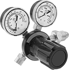
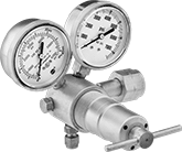
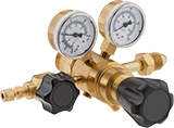
High-Purity Tank-Mount Pressure-Regulating Valves for Inert Gas
- For Use With: See Table
- Temperature Range: -20° to 120° F
Reduce contaminants in research sample systems, emission monitoring systems, chromatography, and other high-purity applications that use argon, helium, nitrogen, or carbon dioxide. These valves have a 316 stainless steel and brass body with a smooth finish to reduce dust collection and internal components designed to protect the seal and diaphragm from contamination. They automatically reduce a high inlet pressure from compressed gas tanks to a lower, stable outlet pressure. All have Compressed Gas Association (CGA) numbered inlet fittings for secure connections to compressed gas tanks. Choose a valve with the same CGA number as your tank and other system components. Outlet fittings are Swagelok® for a leak-free seal around hard metal tubing in high-pressure lines. Also known as instrumentation fittings, Swagelok® fittings are compatible with Parker A-Lok, Gyrolok, Bilok, and Tylok fittings. Valves have a gauge to monitor outlet pressure and a gauge to monitor inlet pressure from the tank.
Choose a valve with a maximum outlet pressure that’s approximately twice your application’s normal operating pressure. Your operating pressure should never exceed 75% of the valve’s maximum outlet pressure.
Single-stage valves reduce pressure in one step, which causes the outlet pressure to fluctuate slightly as you empty the tank. They’re best for applications where a constant outlet pressure isn’t critical.
Two-stage valves progressively reduce pressure over two steps for more consistent outlet pressure at all times. They’re often used in applications that require a constant outlet pressure regardless of the tank level.
Chrome-plated valves add a layer of corrosion resistance.
Inlet | Outlet | |||||||||
|---|---|---|---|---|---|---|---|---|---|---|
| CGA Number | Location | Thread Direction | Pressure Gauge Range, psi | Stage | For Tube OD | Location | Pressure Range, psi | Pressure Adjustment Method | Each | |
Swagelok® Female Outlet × NGO Male Inlet | ||||||||||
Brass Body—316 Stainless Steel Diaphragm and PTFE Seal | ||||||||||
| CGA 580 | Side | Right Hand | 0 to 4,000 | Single | 1/4" | Side | 0 to 15 | Knob | 0000000 | 0000000 |
| CGA 580 | Side | Right Hand | 0 to 4,000 | Single | 1/4" | Side | 0 to 125 | Knob | 0000000 | 000000 |
| CGA 580 | Side | Right Hand | 0 to 4,000 | Single | 1/4" | Side | 0 to 500 | Knob | 0000000 | 000000 |
| CGA 580 | Side | Right Hand | 0 to 4,000 | Two | 1/4" | Side | 0 to 15 | Knob | 0000000 | 000000 |
| CGA 580 | Side | Right Hand | 0 to 4,000 | Two | 1/4" | Side | 0 to 50 | Knob | 0000000 | 000000 |
| CGA 580 | Side | Right Hand | 0 to 4,000 | Two | 1/4" | Side | 0 to 125 | Knob | 0000000 | 000000 |
| CGA 580 | Side | Right Hand | 0 to 4,000 | Two | 1/4" | Side | 0 to 250 | Knob | 0000000 | 000000 |
Chrome-Plated Brass Body—316 Stainless Steel Diaphragm and PTFE Seal | ||||||||||
| CGA 580 | Side | Right Hand | 0 to 4,000 | Two | 1/4" | Side | 0 to 50 | Knob | 0000000 | 000000 |