


Filter by
Shaft Diameter

Length
DFARS Specialty Metals
Shape
OD
RoHS
Export Control Classification Number (ECCN)
Overall Depth
Shaft Type
Mounting Screw Size
Finish
Actuator Style
Door/Hinge-Mount Door Holders
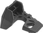 |
Insert these holders three ways—under the door, over the top corner of the door, or over the hinge pin to prop doors open. They’re small and ideal for workers on the move.
Material | Lg. | Ht. | Wd. | Choose a Color | Each | |||
|---|---|---|---|---|---|---|---|---|
| Plastic | 3 1/2" | 2 1/8" | 2 1/2" | Black, Blue, Fluorescent Green, Fluorescent Orange, Fluorescent Yellow, Olive, Pink, Yellow | 1560A11 | 000000 | ||
Hinge-Mount Door Stops
 | 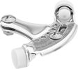 | 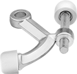 |
Locking Screw | Threaded Stud |
Remove the pin on your door's hinge, slide it through one of these stops, and then insert it back into the hinge to set and adjust the door's opening angle. Both stops have nonmarking rubber pads, which are abrasion resistant. Use the locking screw or threaded stud to make your adjustments.
Door Stops | Replacement Door Bumpers | ||||||||||||
|---|---|---|---|---|---|---|---|---|---|---|---|---|---|
Base | |||||||||||||
Features | Material | Finish | For Hinge Pin Dia. | For Door Opening Angle Setting | Material | Nonmarking | Each | Pkg. Qty. | Pkg. | ||||
| Locking Screw | Steel | Brass | 1/4" to 5/16" | 70° to 100° | Rubber | Yes | 1398A14 | 00000 | 10 | 1398A24 | 00000 | ||
| Threaded Stud | Aluminum | Brass | 1/4" to 5/16" | 85° to 125° | Rubber | Yes | 1398A16 | 0000 | 5 | 1431A56 | 0000 | ||
Hinged Shaft Collars
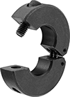 |
Clamping Screw | ||||||||
|---|---|---|---|---|---|---|---|---|
For Shaft Dia. | OD | Wd. | Type | No. Included | Each | |||
Black-Oxide Carbon Steel | ||||||||
| 3/8" | 1 1/16" | 5/16" | Socket Head | 1 | 57145K71 | 000000 | ||
| 1/2" | 1 1/4" | 3/8" | Socket Head | 1 | 57145K72 | 00000 | ||
| 5/8" | 1 1/2" | 13/32" | Socket Head | 1 | 57145K73 | 00000 | ||
| 3/4" | 1 3/4" | 1/2" | Socket Head | 1 | 57145K74 | 00000 | ||
| 7/8" | 1 7/8" | 1/2" | Socket Head | 1 | 57145K75 | 00000 | ||
| 1" | 2" | 1/2" | Socket Head | 1 | 57145K76 | 00000 | ||
| 1 1/8" | 2 1/8" | 1/2" | Socket Head | 1 | 57145K77 | 00000 | ||
| 1 1/4" | 2 1/4" | 1/2" | Socket Head | 1 | 57145K79 | 00000 | ||
| 1 3/8" | 2 3/8" | 1/2" | Socket Head | 1 | 57145K81 | 00000 | ||
| 1 1/2" | 2 1/2" | 1/2" | Socket Head | 1 | 57145K83 | 00000 | ||
| 1 5/8" | 3" | 5/8" | Socket Head | 1 | 57145K84 | 00000 | ||
| 1 3/4" | 3" | 5/8" | Socket Head | 1 | 57145K85 | 00000 | ||
| 1 15/16" | 3 1/4" | 5/8" | Socket Head | 1 | 57145K86 | 00000 | ||
| 2" | 3 1/4" | 5/8" | Socket Head | 1 | 57145K87 | 00000 | ||
| 2 1/4" | 3 1/2" | 5/8" | Socket Head | 1 | 57145K88 | 00000 | ||
| 3" | 4 1/2" | 3/4" | Socket Head | 1 | 57145K91 | 000000 | ||
| 12 mm | 28 mm | 11 mm | Socket Head | 1 | 5706T19 | 00000 | ||
| 16 mm | 34 mm | 13 mm | Socket Head | 1 | 5706T21 | 00000 | ||
| 18 mm | 36 mm | 13 mm | Socket Head | 1 | 5706T22 | 00000 | ||
| 20 mm | 40 mm | 15 mm | Socket Head | 1 | 5706T23 | 00000 | ||
| 25 mm | 45 mm | 15 mm | Socket Head | 1 | 5706T24 | 00000 | ||
| 30 mm | 54 mm | 15 mm | Socket Head | 1 | 5706T25 | 00000 | ||
| 35 mm | 57 mm | 15 mm | Socket Head | 1 | 5706T26 | 00000 | ||
| 40 mm | 60 mm | 15 mm | Socket Head | 1 | 5706T27 | 00000 | ||
| 45 mm | 73 mm | 19 mm | Socket Head | 1 | 5706T28 | 00000 | ||
| 50 mm | 78 mm | 19 mm | Socket Head | 1 | 5706T29 | 00000 | ||
303 Stainless Steel | ||||||||
| 3/8" | 1 1/16" | 5/16" | Socket Head | 1 | 57145K51 | 00000 | ||
| 1/2" | 1 1/4" | 3/8" | Socket Head | 1 | 57145K52 | 00000 | ||
| 5/8" | 1 1/2" | 13/32" | Socket Head | 1 | 57145K53 | 00000 | ||
| 3/4" | 1 3/4" | 1/2" | Socket Head | 1 | 57145K54 | 00000 | ||
| 7/8" | 1 7/8" | 1/2" | Socket Head | 1 | 57145K55 | 00000 | ||
| 1" | 2" | 1/2" | Socket Head | 1 | 57145K56 | 00000 | ||
| 1 1/8" | 2 1/8" | 1/2" | Socket Head | 1 | 57145K57 | 00000 | ||
| 1 1/4" | 2 1/4" | 1/2" | Socket Head | 1 | 57145K58 | 00000 | ||
| 1 3/8" | 2 3/8" | 1/2" | Socket Head | 1 | 57145K59 | 00000 | ||
| 1 1/2" | 2 1/2" | 1/2" | Socket Head | 1 | 57145K61 | 00000 | ||
| 1 3/4" | 3" | 5/8" | Socket Head | 1 | 57145K62 | 000000 | ||
| 2" | 3 1/4" | 5/8" | Socket Head | 1 | 57145K63 | 000000 | ||
| 3" | 4 1/2" | 3/4" | Socket Head | 1 | 57145K64 | 000000 | ||
| 12 mm | 28 mm | 11 mm | Socket Head | 1 | 5719T11 | 00000 | ||
| 16 mm | 34 mm | 13 mm | Socket Head | 1 | 5719T12 | 00000 | ||
| 18 mm | 36 mm | 13 mm | Socket Head | 1 | 5719T13 | 00000 | ||
| 20 mm | 40 mm | 15 mm | Socket Head | 1 | 5719T14 | 00000 | ||
| 25 mm | 45 mm | 15 mm | Socket Head | 1 | 5719T15 | 00000 | ||
| 30 mm | 54 mm | 15 mm | Socket Head | 1 | 5719T16 | 00000 | ||
| 35 mm | 57 mm | 15 mm | Socket Head | 1 | 5719T17 | 000000 | ||
| 40 mm | 60 mm | 15 mm | Socket Head | 1 | 5719T18 | 00000 | ||
| 45 mm | 73 mm | 19 mm | Socket Head | 1 | 5719T19 | 000000 | ||
| 50 mm | 78 mm | 19 mm | Socket Head | 1 | 5719T21 | 00000 | ||
Hinge-Actuated Safety Switches
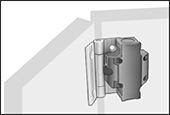 | 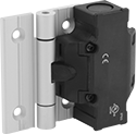 |
Replace the hinges on access doors or machine guards with these switches to keep your team safe from active machinery. Also known as interlock switches, they automatically shut off power to your machinery when the door or guard opens. They can be mounted on flat frames or aluminum T-slotted framing. These switches have positive-force, normally-closed contacts that will open a circuit when the switch is actuated, even if a spring fails or the contacts stick. They’re rated IP65 for protection from washdowns.
Overall | ||||||||||||||
|---|---|---|---|---|---|---|---|---|---|---|---|---|---|---|
For Rail Ht., mm | Mounting Hole Ctr.-to-Ctr. Wd., mm | Switch Action | No. of Terminals | Switch Designation | Switching Current @ Voltage | Wire Connection | Conduit Thread Size | Ht. | Wd. | Dp. | Each | |||
2 Circuits Controlled—2 On | ||||||||||||||
4° Actuation Angle—Aluminum Hinge | ||||||||||||||
| 40 | 44 | Momentary | 4 | DPST-NC | 2 amp @ 230V AC | Screw Terminal | M20 | 3.62" | 4.39" | 1.42" | 7777K108 | 0000000 | ||
3 Circuits Controlled—1 Off and 2 On | ||||||||||||||
4° Actuation Angle—Aluminum Hinge | ||||||||||||||
| 30 | 34 | Momentary | 6 | 3PST-1NO/2NC | 2 amp @ 230V AC | Screw Terminal | M20 | 5.2" | 4.39" | 1.42" | 7777K103 | 000000 | ||
| 35 | 39 | Momentary | 6 | 3PST-1NO/2NC | 2 amp @ 230V AC | Screw Terminal | M20 | 5.2" | 4.39" | 1.42" | 7777K104 | 000000 | ||
| 40 | 44 | Momentary | 6 | 3PST-1NO/2NC | 2 amp @ 230V AC | Screw Terminal | M20 | 3.62" | 4.39" | 1.42" | 7777K48 | 000000 | ||
| 45 | 49 | Momentary | 6 | 3PST-1NO/2NC | 2 amp @ 230V AC | Screw Terminal | M20 | 5.2" | 4.39" | 1.42" | 7777K105 | 000000 | ||
4° Actuation Angle—Stainless Steel Hinge | ||||||||||||||
| 40 | 44 | Momentary | 6 | 3PST-1NO/2NC | 2 amp @ 230V AC | Screw Terminal | M20 | 3.62" | 4.39" | 1.42" | 7777K112 | 000000 | ||
8° Actuation Angle—Aluminum Hinge | ||||||||||||||
| 40 | 44 | Momentary | 6 | 3PST-1NO/2NC | 2 amp @ 230V AC | Screw Terminal | M20 | 3.62" | 4.39" | 1.42" | 7777K101 | 000000 | ||
3 Circuits Controlled—3 On | ||||||||||||||
4° Actuation Angle—Aluminum Hinge | ||||||||||||||
| 30 | 34 | Momentary | 6 | 3PST-NC | 2 amp @ 230V AC | Screw Terminal | M20 | 3.62" | 4.39" | 1.42" | 7777K107 | 000000 | ||
| 40 | 44 | Momentary | 6 | 3PST-NC | 2 amp @ 230V AC | Screw Terminal | M20 | 3.62" | 4.39" | 1.42" | 7777K106 | 000000 | ||
4° Actuation Angle—Stainless Steel Hinge | ||||||||||||||
| 40 | 44 | Momentary | 6 | 3PST-NC | 2 amp @ 230V AC | Screw Terminal | M20 | 3.62" | 4.39" | 1.42" | 7777K113 | 000000 | ||
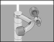
Steel Clamping Hinged Pipe Collars with Wrench Flats
 |
Sized to fit snugly around pipe, these collars have flats so you can turn the collar and your pipe using a standard wrench. This means you don't need to use a pipe wrench, which could scratch the surface of your pipe. These collars are also often used as a stop to support pipe as it passes through floors and walls. They’re also easy to machine, so you can drill and tap a hole through one of the flats to hang a sign. Swing them open to fit over your pipe and tighten them with a single screw—they’re faster to install than two-piece collars. All have captive screws, which won’t fall out of these collars even when fully unthreaded. Made of black-oxide steel, they have some corrosion resistance.
Clamping Screw | ||||||||||||
|---|---|---|---|---|---|---|---|---|---|---|---|---|
For Pipe Size | ID | OD | Wd. | Flat-to-Flat Ht. | Type | Thread Size | Hex Key Size | No. Included | Each | |||
Black-Oxide 1215 Carbon Steel | ||||||||||||
| 3/8 | 0.69" | 1 1/2" | 1/2" | 1.313" | Socket Head | 10-32 | 5/32" | 1 | 7878N11 | 000000 | ||
| 1/2 | 0.857" | 1 3/4" | 1/2" | 1.563" | Socket Head | 1/4"-28 | 3/16" | 1 | 7878N12 | 00000 | ||
| 3/4 | 1.065" | 2" | 1/2" | 1.813" | Socket Head | 1/4"-28 | 3/16" | 1 | 7878N13 | 00000 | ||
| 1 | 1.33" | 2 1/4" | 1/2" | 2.063" | Socket Head | 1/4"-28 | 3/16" | 1 | 7878N14 | 00000 | ||
| 1 1/4 | 1.675" | 3" | 5/8" | 2.313" | Socket Head | 5/16"-24 | 1/4" | 1 | 7878N15 | 00000 | ||
| 1 1/2 | 1.915" | 3 1/4" | 5/8" | 2.813" | Socket Head | 5/16"-24 | 1/4" | 1 | 7878N16 | 00000 | ||
