


Filter by
Thread Size
Threaded Insert Type

Thread Direction


Helical Insert Type


Thread Type
End Type
Export Control Classification Number (ECCN)
DFARS Specialty Metals
Sold As
Tensile Strength
Manufacturer
Helical Threaded Insert Removal Tools
 |
For Thread Size | Mfr. | Each | |||||||||||||||||||||||||||||||||||||||||||||||||||||||||||||||||||||||||||||||||||||||||||||||||
|---|---|---|---|---|---|---|---|---|---|---|---|---|---|---|---|---|---|---|---|---|---|---|---|---|---|---|---|---|---|---|---|---|---|---|---|---|---|---|---|---|---|---|---|---|---|---|---|---|---|---|---|---|---|---|---|---|---|---|---|---|---|---|---|---|---|---|---|---|---|---|---|---|---|---|---|---|---|---|---|---|---|---|---|---|---|---|---|---|---|---|---|---|---|---|---|---|---|---|---|
Standard Profile | |||||||||||||||||||||||||||||||||||||||||||||||||||||||||||||||||||||||||||||||||||||||||||||||||||
| 6-32, 6-40, 8-32, 8-36, 10-24, 10-32, 12-24, 1/4"-20, 1/4"-28, 5/16"-18, 5/16"-24, 3/8"-16, 3/8"-24, 7/16"-14, 7/16"-20, 1/2"-13, 1/2"-20, 9/16"-12, 9/16"-18, 5/8"-11, 5/8"-18, 3/4"-10, 3/4"-16, 7/8"-9, 7/8"-14, 1"-8, 1"-12, 1"-14, M4, M5, M6, M7, M8, M9, M10, M12, M13, M14, M15, M16, M18, M20, M22, M24 | — | 90254A113 | 000000 | ||||||||||||||||||||||||||||||||||||||||||||||||||||||||||||||||||||||||||||||||||||||||||||||||
Narrow Profile | |||||||||||||||||||||||||||||||||||||||||||||||||||||||||||||||||||||||||||||||||||||||||||||||||||
| 7/16"-14, 7/16"-20, 1/2"-13, 1/2"-20, 1/2"-28, 9/16"-12, 9/16"-18, 5/8"-11, 5/8"-18, 5/8"-24, 3/4"-10, 3/4"-16, 3/4"-20, 7/8"-9, 7/8"-14, 7/8"-20, 1"-8, 1"-12, 1"-14, M12, M14, M16, M18, M20, M22, M24 | Heli-Coil | 90254A330 | 00000 | ||||||||||||||||||||||||||||||||||||||||||||||||||||||||||||||||||||||||||||||||||||||||||||||||
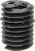
Thread-Locking Threaded Inserts
 |
With Loctite® adhesive already on the threads, these inserts won’t back out or vibrate loose. The adhesive reaches full strength after 72 hours. Unlike helical inserts, you can install them with a standard drill and tap. However, thread-locking inserts are difficult to remove and reuse.
After drilling and tapping your hole, install inserts with a wrench or an installation bit. To use a wrench, thread an insert and two hex nuts onto a bolt. Then, grip and turn the top nut to drive into the hole. For slotted inserts, you can drive with a slotted screwdriver instead.
Standard Wall—Stronger than thin-wall inserts, these are your go-to choice for threading most holes.
Black Phosphate-Coated Steel—These inserts resist occasional moisture.
18-8 Stainless Steel—The choice for wet and outdoor environments, these inserts resist rust and mild chemicals.
Inserts | Installation Tools | ||||||||||||||||||||||||||||||||||||||||||||||||||||||||||||||||||||||||||||||||||||||||||||||||||
|---|---|---|---|---|---|---|---|---|---|---|---|---|---|---|---|---|---|---|---|---|---|---|---|---|---|---|---|---|---|---|---|---|---|---|---|---|---|---|---|---|---|---|---|---|---|---|---|---|---|---|---|---|---|---|---|---|---|---|---|---|---|---|---|---|---|---|---|---|---|---|---|---|---|---|---|---|---|---|---|---|---|---|---|---|---|---|---|---|---|---|---|---|---|---|---|---|---|---|---|
Thread Size | For Tap Thread Size | Installed Lg., mm | Drill Bit Size, mm | For Max. Hole Dia., mm | Drive Style | Pkg. Qty. | Pkg. | Each | |||||||||||||||||||||||||||||||||||||||||||||||||||||||||||||||||||||||||||||||||||||||||||
Standard Wall | |||||||||||||||||||||||||||||||||||||||||||||||||||||||||||||||||||||||||||||||||||||||||||||||||||
Black Phosphate-Coated Steel | |||||||||||||||||||||||||||||||||||||||||||||||||||||||||||||||||||||||||||||||||||||||||||||||||||
| M16 x 2 mm | M24 x 3 mm | 20 | 21 | 21 | Slotted | 1 | 97084A270 | 00000 | 94110A190 | 000000 | |||||||||||||||||||||||||||||||||||||||||||||||||||||||||||||||||||||||||||||||||||||||||
| M24 x 3 mm | M36 x 4 mm | 30 | 33 | 33 | Slotted | 1 | 97084A317 | 00000 | 94110A250 | 00000 | |||||||||||||||||||||||||||||||||||||||||||||||||||||||||||||||||||||||||||||||||||||||||
18-8 Stainless Steel | |||||||||||||||||||||||||||||||||||||||||||||||||||||||||||||||||||||||||||||||||||||||||||||||||||
| M16 x 2 mm | M24 x 3 mm | 20 | 21 | 21 | Slotted | 1 | 97120A270 | 0000 | 94110A190 | 00000 | |||||||||||||||||||||||||||||||||||||||||||||||||||||||||||||||||||||||||||||||||||||||||
Key-Locking Threaded Inserts for Soft Metal
 |
Add strong threads in soft metal, such as aluminum. The keys on these inserts drive into holes to hold more securely than thread-locking or helical inserts. They prevent slipping and rotating, so they’re stable enough for use in vehicle or aerospace parts that experience heavy vibration. These inserts are comparable to Keensert inserts.
To install, drill and tap a hole in your material. Then, thread the insert onto the installation tool and screw it into the hole. Place the tool over the keys and hit it with a hammer to drive them in.
Standard Wall—Stronger than thin-wall inserts, these are your go-to choice for threading most holes.
Black Phosphate-Coated Steel—These inserts resist occasional moisture.
18-8 Stainless Steel—The choice for wet and outdoor environments, these inserts resist rust and mild chemicals.
Inserts | Installation Tools | Inserts with Installation Tools | |||||||||||||||||||||||||||||||||||||||||||||||||||||||||||||||||||||||||||||||||||||||||||||||||
|---|---|---|---|---|---|---|---|---|---|---|---|---|---|---|---|---|---|---|---|---|---|---|---|---|---|---|---|---|---|---|---|---|---|---|---|---|---|---|---|---|---|---|---|---|---|---|---|---|---|---|---|---|---|---|---|---|---|---|---|---|---|---|---|---|---|---|---|---|---|---|---|---|---|---|---|---|---|---|---|---|---|---|---|---|---|---|---|---|---|---|---|---|---|---|---|---|---|---|---|
Each | |||||||||||||||||||||||||||||||||||||||||||||||||||||||||||||||||||||||||||||||||||||||||||||||||||
Thread Size | For Tap Thread Size | Installed Lg., mm | Drill Bit Size, mm | For Max. Hole Dia., mm | No. of Locking Keys | 1-9 | 10-Up | Each | No. of Inserts Included | Each | |||||||||||||||||||||||||||||||||||||||||||||||||||||||||||||||||||||||||||||||||||||||||
Standard Wall | |||||||||||||||||||||||||||||||||||||||||||||||||||||||||||||||||||||||||||||||||||||||||||||||||||
Black Phosphate-Coated Steel | |||||||||||||||||||||||||||||||||||||||||||||||||||||||||||||||||||||||||||||||||||||||||||||||||||
| M18 x 1.5 mm | M24 x 1.5 mm | 24 | 22.5 | 22.5 | 4 | 90245A197 | 000000 | 000000 | 94010A350 | 000000 | 2 | 90245A321 | 000000 | ||||||||||||||||||||||||||||||||||||||||||||||||||||||||||||||||||||||||||||||||||||||
| M24 x 2 mm | M33 x 2 mm | 33 | 31 | 31 | 4 | 90245A217 | 00000 | 00000 | 94010A365 | 00000 | — | ——— | 0 | ||||||||||||||||||||||||||||||||||||||||||||||||||||||||||||||||||||||||||||||||||||||
| M24 x 3 mm | M33 x 2 mm | 33 | 31 | 31 | 4 | 90245A213 | 00000 | 00000 | 94010A365 | 00000 | 2 | 90245A341 | 000000 | ||||||||||||||||||||||||||||||||||||||||||||||||||||||||||||||||||||||||||||||||||||||
18-8 Stainless Steel | |||||||||||||||||||||||||||||||||||||||||||||||||||||||||||||||||||||||||||||||||||||||||||||||||||
| M18 x 1.5 mm | M24 x 1.5 mm | 24 | 22.5 | 22.5 | 4 | 93715A665 | 00000 | 00000 | 94010A350 | 00000 | 2 | 93715A475 | 000000 | ||||||||||||||||||||||||||||||||||||||||||||||||||||||||||||||||||||||||||||||||||||||
| M24 x 3 mm | M33 x 2 mm | 33 | 31 | 31 | 4 | 93715A685 | 00000 | 00000 | 94010A365 | 00000 | — | ——— | 0 | ||||||||||||||||||||||||||||||||||||||||||||||||||||||||||||||||||||||||||||||||||||||
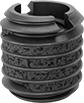
Thread-Locking Threaded Insert Assortments
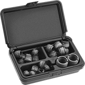 |
These assortments include various sizes of thread-locking inserts, which won’t back out or loosen from vibration. Also known as E-Z Lok, they come with Loctite® adhesive already applied, and the adhesive reaches full strength after 72 hours. After drilling and tapping your hole, install inserts with a wrench or use an installation bit (not included). To use a wrench, thread an insert and two hex nuts onto a bolt. Then, grip and turn the top nut to drive into the hole.
Standard Wall—Stronger than thin-wall inserts, these are your go-to choice for threading most holes.
Black Phosphate-Coated Steel—These inserts resist occasional moisture.
18-8 Stainless Steel—The choice for wet and outdoor environments, these inserts resist rust and mild chemicals.
For Tap | |||||||||||||||||||||||||||||||||||||||||||||||||||||||||||||||||||||||||||||||||||||||||||||||||||
|---|---|---|---|---|---|---|---|---|---|---|---|---|---|---|---|---|---|---|---|---|---|---|---|---|---|---|---|---|---|---|---|---|---|---|---|---|---|---|---|---|---|---|---|---|---|---|---|---|---|---|---|---|---|---|---|---|---|---|---|---|---|---|---|---|---|---|---|---|---|---|---|---|---|---|---|---|---|---|---|---|---|---|---|---|---|---|---|---|---|---|---|---|---|---|---|---|---|---|---|
No. of Inserts Included | Includes | Thread Spacing | Thread Size | Thread Pitch | Drill Bit Size | For Maximum Hole Diameter | Drive Style | Each | |||||||||||||||||||||||||||||||||||||||||||||||||||||||||||||||||||||||||||||||||||||||||||
Standard Wall | |||||||||||||||||||||||||||||||||||||||||||||||||||||||||||||||||||||||||||||||||||||||||||||||||||
Black Phosphate-Coated Steel | |||||||||||||||||||||||||||||||||||||||||||||||||||||||||||||||||||||||||||||||||||||||||||||||||||
| 33 | M8×1.25 mm Thread × 12.5 mm Installed Lg. (10 Each) M10×1.5 mm Thread × 17 mm Installed Lg. (10 Each) M12×1.75 mm Thread × 17 mm Installed Lg. (8 Each) M16×2 mm Thread × 20 mm Installed Lg. (5 Each) | Coarse | M12 M16 M16 M24 | 1.75 mm 2 mm 2 mm 3 mm | 10.4 mm 14 mm 14 mm 21 mm | 10.4 mm 14 mm 14 mm 21 mm | Slotted | 97084A290 | 0000000 | ||||||||||||||||||||||||||||||||||||||||||||||||||||||||||||||||||||||||||||||||||||||||||
18-8 Stainless Steel | |||||||||||||||||||||||||||||||||||||||||||||||||||||||||||||||||||||||||||||||||||||||||||||||||||
| 33 | M8×1.25 mm Thread × 12.5 mm Installed Lg. (10 Each) M10×1.5 mm Thread × 17 mm Installed Lg. (10 Each) M12×1.75 mm Thread × 17 mm Installed Lg. (8 Each) M16×2 mm Thread × 20 mm Installed Lg. (5 Each) | Coarse | M12 M16 M16 M24 | 1.75 mm 2 mm 2 mm 3 mm | 10.4 mm 14 mm 14 mm 21 mm | 10.4 mm 14 mm 14 mm 21 mm | Slotted | 97120A035 | 000000 | ||||||||||||||||||||||||||||||||||||||||||||||||||||||||||||||||||||||||||||||||||||||||||
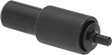
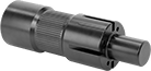
Thread-In Quick-Release Pin Receptacles
 | 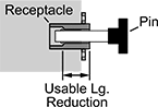 |
Use a screwdriver to install these receptacles in a threaded hole. Use them to secure quick-release pins when you can't drill a through hole. They're made of 18-8 stainless steel for a balance of strength and corrosion resistance, and passivated for added protection against corrosion and oxidation.
For Pin Dia., mm | Barrel OD, mm | Overall Lg., mm | Usable Lg. Reduction, mm | Thread Size | Material | Passivation | Each | ||||||||||||||||||||||||||||||||||||||||||||||||||||||||||||||||||||||||||||||||||||||||||||
|---|---|---|---|---|---|---|---|---|---|---|---|---|---|---|---|---|---|---|---|---|---|---|---|---|---|---|---|---|---|---|---|---|---|---|---|---|---|---|---|---|---|---|---|---|---|---|---|---|---|---|---|---|---|---|---|---|---|---|---|---|---|---|---|---|---|---|---|---|---|---|---|---|---|---|---|---|---|---|---|---|---|---|---|---|---|---|---|---|---|---|---|---|---|---|---|---|---|---|---|
Round Mounting Flange | |||||||||||||||||||||||||||||||||||||||||||||||||||||||||||||||||||||||||||||||||||||||||||||||||||
| 16 | 24 | 24 | 6 | M24 × 2 mm | 18-8 Stainless Steel | Passivated | 94715A307 | 000000 | |||||||||||||||||||||||||||||||||||||||||||||||||||||||||||||||||||||||||||||||||||||||||||
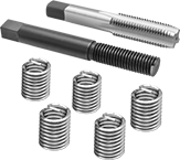
Helical Threaded Inserts
 |
Pronged |
Restore, reinforce, or create threads in metal. The tough coils on these inserts expand once installed to anchor in a tapped hole. Also known as Heli-Coil inserts, they're often used in engine heads and machinery housings where strong connections are critical. Unlike threadlocking inserts, you can remove and reuse them without them losing their strength.
Installation requires a drill bit, a helical insert tap, and an installation tool.
Pronged—The prong attaches to an installation tool for precise control as you drive inserts in. Remove the prong with a punch or break-off tool before inserting a screw.
18-8 Stainless Steel—The choice for wet and outdoor environments, these inserts resist rust and mild chemicals.
Inserts | Through-Hole Taps | Closed-End Hole Taps | Installation Tools | Inserts with Installation Tools | |||||||||||||||||||||||||||||||||||||||||||||||||||||||||||||||||||||||||||||||||||||||||||||||
|---|---|---|---|---|---|---|---|---|---|---|---|---|---|---|---|---|---|---|---|---|---|---|---|---|---|---|---|---|---|---|---|---|---|---|---|---|---|---|---|---|---|---|---|---|---|---|---|---|---|---|---|---|---|---|---|---|---|---|---|---|---|---|---|---|---|---|---|---|---|---|---|---|---|---|---|---|---|---|---|---|---|---|---|---|---|---|---|---|---|---|---|---|---|---|---|---|---|---|---|
Thread Size | Installed Lg., mm | Drill Bit Size | For Max. Hole Dia. | Specs. Met | Pkg. Qty. | Pkg. | Each | Each | Each | No. of Inserts Included | Each | ||||||||||||||||||||||||||||||||||||||||||||||||||||||||||||||||||||||||||||||||||||||||
Pronged | |||||||||||||||||||||||||||||||||||||||||||||||||||||||||||||||||||||||||||||||||||||||||||||||||||
18-8 Stainless Steel | |||||||||||||||||||||||||||||||||||||||||||||||||||||||||||||||||||||||||||||||||||||||||||||||||||
| M24 x 3 mm | 36 | 31/32" | 0.969" | SAE MA3279-179 | 1 | 92450A125 | 00000 | 92450A325 | 0000000 | 91709A340 | 0000000 | 92450A523 | 000000 | 5 | 91732A969 | 0000000 | |||||||||||||||||||||||||||||||||||||||||||||||||||||||||||||||||||||||||||||||||||
Installation Bits for Slotted-Drive Threaded Inserts
 |
For Thread Size | Hex Shank Size | Each | ||
|---|---|---|---|---|
| M20, M24 | 3/8" | 94110A250 | 000000 |
Key-Locking Threaded Insert Drivers
Helical Insert Taps
Key-Locking Threaded Inserts with Installation Tools
 |
Paired with the right tool for installation, these inserts create strong threads in soft metal, such as aluminum. They have keys that drive into material to prevent inserts from slipping and rotating in the hole.
Standard Wall—Stronger than thin-wall inserts, these are your go-to choice for threading most holes.
Black Phosphate-Coated Steel—These inserts resist occasional moisture.
18-8 Stainless Steel—The choice for wet and outdoor environments, these inserts resist rust and mild chemicals.
Thread Size | For Tap Thread Size | Installed Lg., mm | Drill Bit Size, mm | For Max. Hole Dia., mm | No. of Locking Keys | No. of Inserts Included | Each | ||||||||||||||||||||||||||||||||||||||||||||||||||||||||||||||||||||||||||||||||||||||||||||
|---|---|---|---|---|---|---|---|---|---|---|---|---|---|---|---|---|---|---|---|---|---|---|---|---|---|---|---|---|---|---|---|---|---|---|---|---|---|---|---|---|---|---|---|---|---|---|---|---|---|---|---|---|---|---|---|---|---|---|---|---|---|---|---|---|---|---|---|---|---|---|---|---|---|---|---|---|---|---|---|---|---|---|---|---|---|---|---|---|---|---|---|---|---|---|---|---|---|---|---|
Standard Wall | |||||||||||||||||||||||||||||||||||||||||||||||||||||||||||||||||||||||||||||||||||||||||||||||||||
Black Phosphate-Coated Steel | |||||||||||||||||||||||||||||||||||||||||||||||||||||||||||||||||||||||||||||||||||||||||||||||||||
| M18 x 1.5 mm | M24 x 1.5 mm | 24 | 22.5 | 22.5 | 4 | 2 | 90245A321 | 000000 | |||||||||||||||||||||||||||||||||||||||||||||||||||||||||||||||||||||||||||||||||||||||||||
| M24 x 3 mm | M33 x 2 mm | 33 | 31 | 31 | 4 | 2 | 90245A341 | 000000 | |||||||||||||||||||||||||||||||||||||||||||||||||||||||||||||||||||||||||||||||||||||||||||
18-8 Stainless Steel | |||||||||||||||||||||||||||||||||||||||||||||||||||||||||||||||||||||||||||||||||||||||||||||||||||
| M18 x 1.5 mm | M24 x 1.5 mm | 24 | 22.5 | 22.5 | 4 | 2 | 93715A475 | 000000 | |||||||||||||||||||||||||||||||||||||||||||||||||||||||||||||||||||||||||||||||||||||||||||
Helical Threaded Insert Installation and Prong Break-Off Tools
T-Handle |
For Thread Size | Handle Style | Each | |||||||||||||||||||||||||||||||||||||||||||||||||||||||||||||||||||||||||||||||||||||||||||||||||
|---|---|---|---|---|---|---|---|---|---|---|---|---|---|---|---|---|---|---|---|---|---|---|---|---|---|---|---|---|---|---|---|---|---|---|---|---|---|---|---|---|---|---|---|---|---|---|---|---|---|---|---|---|---|---|---|---|---|---|---|---|---|---|---|---|---|---|---|---|---|---|---|---|---|---|---|---|---|---|---|---|---|---|---|---|---|---|---|---|---|---|---|---|---|---|---|---|---|---|---|
Metric Thread | |||||||||||||||||||||||||||||||||||||||||||||||||||||||||||||||||||||||||||||||||||||||||||||||||||
| M24 × 3 mm | T-Handle | 92450A523 | 000000 | ||||||||||||||||||||||||||||||||||||||||||||||||||||||||||||||||||||||||||||||||||||||||||||||||
Screw-Locking Seize-Resistant Key-Locking Threaded Inserts for Soft Metal
 |
Create the tightest hold in aluminum and other soft metal without screws sticking. The lubricant on these inserts eases installation, and the irregularly shaped threads won’t let screws back out from vibration. Inserts have keys that drive into material to prevent them from slipping or rotating in the hole.
To install, drill and tap a hole in your material. Then, thread the insert onto the installation tool and screw it into the hole. Place the tool over the keys and hit it with a hammer to drive them in.
Standard Wall—Stronger than thin-wall inserts, these are your go-to choice for threading most holes.
Dry-Film-Lubricated Cadmium-Plated Steel—The plating creates a barrier against rust.
Screw-In Plugs for Pipe and Tubing
For Straight-Thread Fittings
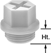 |
Nylon |
Thread | |||||||||||||||||||||||||||||||||||||||||||||||||||||||||||||||||||||||||||||||||||||||||||||||||||
|---|---|---|---|---|---|---|---|---|---|---|---|---|---|---|---|---|---|---|---|---|---|---|---|---|---|---|---|---|---|---|---|---|---|---|---|---|---|---|---|---|---|---|---|---|---|---|---|---|---|---|---|---|---|---|---|---|---|---|---|---|---|---|---|---|---|---|---|---|---|---|---|---|---|---|---|---|---|---|---|---|---|---|---|---|---|---|---|---|---|---|---|---|---|---|---|---|---|---|---|
Size | Type | Ht., mm | Max. Temp., ° F | Color | Pkg. Qty. | Pkg. | |||||||||||||||||||||||||||||||||||||||||||||||||||||||||||||||||||||||||||||||||||||||||||||
Nylon | |||||||||||||||||||||||||||||||||||||||||||||||||||||||||||||||||||||||||||||||||||||||||||||||||||
| M24 × 1.5 mm | Metric | 12 | 150 | Yellow | 25 | 5481K31 | 000000 | ||||||||||||||||||||||||||||||||||||||||||||||||||||||||||||||||||||||||||||||||||||||||||||
Screw-Locking Helical Threaded Inserts
 |
Pronged |
The irregularly shaped threads tightly grip screws to prevent them from loosening or backing out under vibration. Use these inserts to create or repair threads in pumps and other machinery that shakes and rattles. Also known as Heli-Coil inserts.
Installation requires a drill bit, a helical insert tap, and an installation tool.
Pronged—The prong attaches to an installation tool for precise control as you drive inserts in. Remove the prong with a punch or break-off tool before inserting a screw.
18-8 Stainless Steel—The choice for wet and outdoor environments, these inserts resist rust and mild chemicals.
Helical Threaded Inserts with Installation Tools
 |
Installation Tool and Through-Hole Tap |
Quickly restore stripped threads—these inserts come with through-hole taps and installation tools. The tough coils on these inserts expand once installed to anchor in a tapped hole.
Pronged—The prong attaches to an installation tool for precise control as you drive inserts in. Remove the prong with a punch or break-off tool before inserting a screw.
18-8 Stainless Steel—The choice for wet and outdoor environments, these inserts resist rust and mild chemicals.
Thread Size | Installed Lg., mm | Drill Bit Size | For Max. Hole Dia. | No. of Inserts Included | Includes | Each | |||||||||||||||||||||||||||||||||||||||||||||||||||||||||||||||||||||||||||||||||||||||||||||
|---|---|---|---|---|---|---|---|---|---|---|---|---|---|---|---|---|---|---|---|---|---|---|---|---|---|---|---|---|---|---|---|---|---|---|---|---|---|---|---|---|---|---|---|---|---|---|---|---|---|---|---|---|---|---|---|---|---|---|---|---|---|---|---|---|---|---|---|---|---|---|---|---|---|---|---|---|---|---|---|---|---|---|---|---|---|---|---|---|---|---|---|---|---|---|---|---|---|---|---|
Pronged | |||||||||||||||||||||||||||||||||||||||||||||||||||||||||||||||||||||||||||||||||||||||||||||||||||
18-8 Stainless Steel | |||||||||||||||||||||||||||||||||||||||||||||||||||||||||||||||||||||||||||||||||||||||||||||||||||
| M24 x 3 mm | 36 | 31/32" | 0.969" | 5 | Installation Tool Through-Hole Tap | 91732A969 | 0000000 | ||||||||||||||||||||||||||||||||||||||||||||||||||||||||||||||||||||||||||||||||||||||||||||
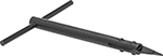
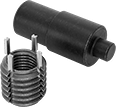
Key-Locking Threaded Insert Installation Tools
 | 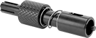 |
Style A | Style D |
Thread inserts and drive down their keys with a single tool. These tools are compatible with Keensert inserts.
Threaded Insert Installation Tools
|
Style A |
For Thread Size | For Tap Thread Size | Style | Features | Each | |||||||||||||||||||||||||||||||||||||||||||||||||||||||||||||||||||||||||||||||||||||||||||||||
|---|---|---|---|---|---|---|---|---|---|---|---|---|---|---|---|---|---|---|---|---|---|---|---|---|---|---|---|---|---|---|---|---|---|---|---|---|---|---|---|---|---|---|---|---|---|---|---|---|---|---|---|---|---|---|---|---|---|---|---|---|---|---|---|---|---|---|---|---|---|---|---|---|---|---|---|---|---|---|---|---|---|---|---|---|---|---|---|---|---|---|---|---|---|---|---|---|---|---|---|
For Thick-Wall Inserts | |||||||||||||||||||||||||||||||||||||||||||||||||||||||||||||||||||||||||||||||||||||||||||||||||||
| M24 | M33 | A | Slotted End | 6721N93 | 000000 | ||||||||||||||||||||||||||||||||||||||||||||||||||||||||||||||||||||||||||||||||||||||||||||||
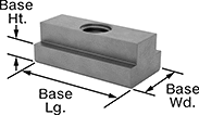
Drop-In T-Slot Nuts
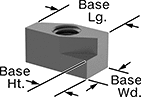 |
Metric
Base, mm | Fully Threaded | ||||||||||||||||||||||||||||||||||||||||||||||||||||||||||||||||||||||||||||||||||||||||||||||||||
|---|---|---|---|---|---|---|---|---|---|---|---|---|---|---|---|---|---|---|---|---|---|---|---|---|---|---|---|---|---|---|---|---|---|---|---|---|---|---|---|---|---|---|---|---|---|---|---|---|---|---|---|---|---|---|---|---|---|---|---|---|---|---|---|---|---|---|---|---|---|---|---|---|---|---|---|---|---|---|---|---|---|---|---|---|---|---|---|---|---|---|---|---|---|---|---|---|---|---|---|
For Slot Wd., mm | Thread Size | Lg. | Wd. | Ht. | Overall Ht., mm | Each | |||||||||||||||||||||||||||||||||||||||||||||||||||||||||||||||||||||||||||||||||||||||||||||
Black-Oxide Steel | |||||||||||||||||||||||||||||||||||||||||||||||||||||||||||||||||||||||||||||||||||||||||||||||||||
| 28 | M24 × 3 mm | 54 | 27.7 | 18 | 36 | 90799A616 | 000000 | ||||||||||||||||||||||||||||||||||||||||||||||||||||||||||||||||||||||||||||||||||||||||||||
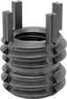
Easy-Start Helical Threaded Insert Installation Tools
Threaded Insert Installation Tools with Depth Stop
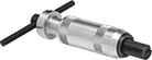 |  |
T-Handle | Prong Slot Drive |
Ensure consistent installation across multiple inserts. Set your desired installation depth, and the stop will prevent you from driving your insert any further.
Prong Slot Drive Helical Insert Tool—Install both left- and right-hand threaded inserts with any thread pitch. However, these tools don't align the threads like threaded-drive tools, so installation may be more difficult.
For Thread Size | Handle Style | Helical Insert Tool Drive Type | For Use With | Each | |||||||||||||||||||||||||||||||||||||||||||||||||||||||||||||||||||||||||||||||||||||||||||||||
|---|---|---|---|---|---|---|---|---|---|---|---|---|---|---|---|---|---|---|---|---|---|---|---|---|---|---|---|---|---|---|---|---|---|---|---|---|---|---|---|---|---|---|---|---|---|---|---|---|---|---|---|---|---|---|---|---|---|---|---|---|---|---|---|---|---|---|---|---|---|---|---|---|---|---|---|---|---|---|---|---|---|---|---|---|---|---|---|---|---|---|---|---|---|---|---|---|---|---|---|
Metric Thread | |||||||||||||||||||||||||||||||||||||||||||||||||||||||||||||||||||||||||||||||||||||||||||||||||||
| M24 × 3 mm | T-Handle | Prong Slot | Helical Inserts, Screw-Locking Helical Inserts | 1338N74 | 0000000 | ||||||||||||||||||||||||||||||||||||||||||||||||||||||||||||||||||||||||||||||||||||||||||||||
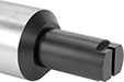
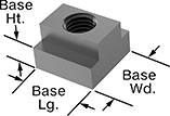
Extra-Long T-Slot Nuts
Metric
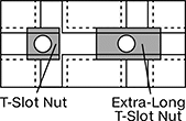 |  |
T-Slot Nut and Extra-Long T-Slot Nut Shown Installed Within Cross-Slot |
Base, mm | Fully Threaded | ||||||||||||||||||||||||||||||||||||||||||||||||||||||||||||||||||||||||||||||||||||||||||||||||||
|---|---|---|---|---|---|---|---|---|---|---|---|---|---|---|---|---|---|---|---|---|---|---|---|---|---|---|---|---|---|---|---|---|---|---|---|---|---|---|---|---|---|---|---|---|---|---|---|---|---|---|---|---|---|---|---|---|---|---|---|---|---|---|---|---|---|---|---|---|---|---|---|---|---|---|---|---|---|---|---|---|---|---|---|---|---|---|---|---|---|---|---|---|---|---|---|---|---|---|---|
For Slot Wd., mm | Thread Size | Lg. | Wd. | Ht. | Overall Ht., mm | Specs. Met | Each | ||||||||||||||||||||||||||||||||||||||||||||||||||||||||||||||||||||||||||||||||||||||||||||
Steel | |||||||||||||||||||||||||||||||||||||||||||||||||||||||||||||||||||||||||||||||||||||||||||||||||||
| 28 | M24 × 2.5 mm | 88 | 44 | 18 | 36 | DIN 508 | 90894A241 | 000000 | |||||||||||||||||||||||||||||||||||||||||||||||||||||||||||||||||||||||||||||||||||||||||||
Shock-Absorbing Swivel Leveling Mounts with Threaded Stud
T-Slot Nuts
Metric
 |
Black-Oxide Steel—Create a finished look with a dark, matte coating. These nuts offer minimal corrosion resistance, so they're best for dry environments.
Fully Threaded—Fully threaded nuts allow a stud to extend beyond the bottom of the nut.
Partially Threaded—Partially threaded nuts keep studs from traveling past the bottom of the nut and damaging your table.
DIN 508—Nuts meet DIN dimensional and material requirements. Slide them into DIN 650 T-slots.
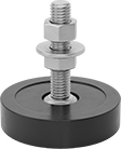
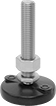
Vibration-Damping Swivel Leveling Mounts with Threaded Stud
 |
With Cushion |
A rubber cushion reduces vibration to protect components and extend your machine’s life. For mounting versatility, you can install them in either threaded holes or unthreaded through holes at the bottom of equipment.
304 Stainless Steel Base—The choice for most wet locations, these mounts can withstand repeated washdowns without corroding. However, they won't hold up to cleaning solutions that contain harsh chemicals like 316 stainless steel can.
Rubber Cushion—In addition to reducing vibration, the cushion grips surfaces so vibrating equipment doesn't slide. It also cuts down on noise and protects floors from scrapes and gouges.
With Rubber Cushion | |||||||||||||||||||||||||||||||||||||||||||||||||||||||||||||||||||||||||||||||||||||||||||||||||||
|---|---|---|---|---|---|---|---|---|---|---|---|---|---|---|---|---|---|---|---|---|---|---|---|---|---|---|---|---|---|---|---|---|---|---|---|---|---|---|---|---|---|---|---|---|---|---|---|---|---|---|---|---|---|---|---|---|---|---|---|---|---|---|---|---|---|---|---|---|---|---|---|---|---|---|---|---|---|---|---|---|---|---|---|---|---|---|---|---|---|---|---|---|---|---|---|---|---|---|---|
Thread Size | Thread Lg. | Swivel Range of Motion | Base Dia. | Cap. per Mount, lb. | Deflection @ Cap. | Overall Ht. | Cushion Material | Each | |||||||||||||||||||||||||||||||||||||||||||||||||||||||||||||||||||||||||||||||||||||||||||
304 Stainless Steel Base and Stud | |||||||||||||||||||||||||||||||||||||||||||||||||||||||||||||||||||||||||||||||||||||||||||||||||||
| M24 × 3 mm | 4 3/4" | 7.5° | 5 1/2" | 3,000 | 0.17" | 7" | Buna-N | 6221K151 | 0000000 | ||||||||||||||||||||||||||||||||||||||||||||||||||||||||||||||||||||||||||||||||||||||||||
| M24 × 3 mm | 5 15/16" | 7.5° | 3 7/8" | 2,000 | 0.12" | 7 5/8" | Buna-N | 6221K148 | 000000 | ||||||||||||||||||||||||||||||||||||||||||||||||||||||||||||||||||||||||||||||||||||||||||
| M24 × 3 mm | 5 15/16" | 7.5° | 5 1/2" | 4,000 | 0.17" | 8 1/8" | Buna-N | 6221K152 | 000000 | ||||||||||||||||||||||||||||||||||||||||||||||||||||||||||||||||||||||||||||||||||||||||||
Stay-Put Swivel Leveling Mounts with Threaded Stud
 |  |
Without Cushion | With Cushion |
Bolt down machines so they don’t creep across the floor or tip over. These mounts have punch-out holes for securing equipment that you don’t need to move. The ball-and-socket joint in the base swivels to compensate for slightly sloped and pitted floors. For mounting versatility, you can install these mounts in either threaded holes or unthreaded through holes at the bottom of equipment.
Glass-Filled Nylon Base and Zinc-Plated Steel Stud—These mounts are suitable for damp environments, but they won’t hold up to high-pressure washdowns and cleaners that contain harsh chemicals.
Rubber Cushion—A cushion under the base protects floors from scrapes and gouges.
Mounting Holes | Without Cushion | With Rubber Cushion | |||||||||||||||||||||||||||||||||||||||||||||||||||||||||||||||||||||||||||||||||||||||||||||||||
|---|---|---|---|---|---|---|---|---|---|---|---|---|---|---|---|---|---|---|---|---|---|---|---|---|---|---|---|---|---|---|---|---|---|---|---|---|---|---|---|---|---|---|---|---|---|---|---|---|---|---|---|---|---|---|---|---|---|---|---|---|---|---|---|---|---|---|---|---|---|---|---|---|---|---|---|---|---|---|---|---|---|---|---|---|---|---|---|---|---|---|---|---|---|---|---|---|---|---|---|
Thread Size | Thread Lg., mm | Cap. per Mount, lb. | Swivel Range of Motion | Base Dia., mm | No. of | Fasteners Included | Dia., mm | Ctr.-to-Ctr. Lg., mm | Overall Ht., mm | Each | Overall Ht., mm | Cushion Material | Each | ||||||||||||||||||||||||||||||||||||||||||||||||||||||||||||||||||||||||||||||||||||||
Glass-Filled Nylon Base and Zinc-Plated Steel Stud | |||||||||||||||||||||||||||||||||||||||||||||||||||||||||||||||||||||||||||||||||||||||||||||||||||
| M24 × 3 mm | 152 | 7,500 | 7.5° | 102 | 2 | No | 11.9 | 68.8 | 185 | 6992K25 | 000000 | 186.6 | Neoprene | 6992K49 | 000000 | ||||||||||||||||||||||||||||||||||||||||||||||||||||||||||||||||||||||||||||||||||||
| M24 × 3 mm | 152 | 10,000 | 7.5° | 127 | 2 | No | 12 | 98 | 210 | 6992K27 | 00000 | 211.6 | Neoprene | 6992K753 | 00000 | ||||||||||||||||||||||||||||||||||||||||||||||||||||||||||||||||||||||||||||||||||||
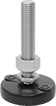
Swivel Leveling Mounts with Threaded Hole
 |
Without Cushion |
 |
With Cushion |
Keep equipment level on slightly sloped and pitted floors with mounts that have a ball-and-socket joint in the base. Add your own stud to create a custom-length mount that you can install in either threaded holes or unthreaded through holes.
Nickel-Plated Steel Base—With a shiny appearance, these mounts create a finished look. They're best for dry environments since the nickel plating offers minimal corrosion resistance.
Zinc-Yellow-Chromate-Plated Steel Base—More corrosion resistant than nickel-plated steel, these mounts are suitable for damp environments. However, they won’t hold up to chemical cleaners, high-pressure washdowns, and other harsh conditions like stainless steel can.
303 Stainless Steel Base—The choice for most wet locations, these mounts can withstand repeated washdowns without corroding. However, they won't hold up to cleaning solutions that contain harsh chemicals like 316 stainless steel can.
Rubber Cushion—A cushion under the base grips surfaces so vibrating equipment doesn't slide. It also protects floors from scrapes and gouges.
Without Cushion | With Rubber Cushion | ||||||||||||||||||||||||||||||||||||||||||||||||||||||||||||||||||||||||||||||||||||||||||||||||||
|---|---|---|---|---|---|---|---|---|---|---|---|---|---|---|---|---|---|---|---|---|---|---|---|---|---|---|---|---|---|---|---|---|---|---|---|---|---|---|---|---|---|---|---|---|---|---|---|---|---|---|---|---|---|---|---|---|---|---|---|---|---|---|---|---|---|---|---|---|---|---|---|---|---|---|---|---|---|---|---|---|---|---|---|---|---|---|---|---|---|---|---|---|---|---|---|---|---|---|---|
Thread Size | Thread Dp., mm | Swivel Range of Motion | Base Dia., mm | Cap. per Mount, lb. | Overall Ht., mm | Each | Cap. per Mount, lb. | Overall Ht., mm | Cushion Material | Each | |||||||||||||||||||||||||||||||||||||||||||||||||||||||||||||||||||||||||||||||||||||||||
Nickel-Plated Steel Base | |||||||||||||||||||||||||||||||||||||||||||||||||||||||||||||||||||||||||||||||||||||||||||||||||||
| M24 × 3 mm | 17.7 | 7.5° | 102 | 19,840 | 48 | 6103K607 | 000000 | 14,990 | 51 | Natural Rubber | 6103K615 | 000000 | |||||||||||||||||||||||||||||||||||||||||||||||||||||||||||||||||||||||||||||||||||||||
Zinc-Yellow-Chromate-Plated Steel Base | |||||||||||||||||||||||||||||||||||||||||||||||||||||||||||||||||||||||||||||||||||||||||||||||||||
| M24 × 3 mm | 17.5 | 7.5° | 102 | 19,800 | 48 | 6120K37 | 00000 | 14,960 | 51 | Natural Rubber | 6120K45 | 00000 | |||||||||||||||||||||||||||||||||||||||||||||||||||||||||||||||||||||||||||||||||||||||
303 Stainless Steel Base | |||||||||||||||||||||||||||||||||||||||||||||||||||||||||||||||||||||||||||||||||||||||||||||||||||
| M24 × 3 mm | 17.5 | 7.5° | 102 | 19,800 | 48 | 6120K53 | 00000 | — | — | — | ——— | 0 | |||||||||||||||||||||||||||||||||||||||||||||||||||||||||||||||||||||||||||||||||||||||
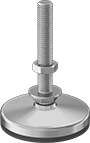
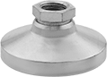
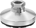
Swivel Leveling Mounts with Threaded Stud
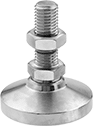 |
Without Cushion |
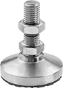 |
With Cushion |
Keep equipment level on slightly sloped and pitted floors with mounts that have a ball-and-socket joint in the base. For mounting versatility, you can install them in either threaded holes or unthreaded through holes at the bottom of equipment.
Nickel-Plated Steel Base—With a shiny appearance, these mounts create a finished look. They're best for dry environments since the nickel plating offers minimal corrosion resistance.
Zinc-Yellow-Chromate-Plated Steel Base—More corrosion resistant than nickel-plated steel, these mounts are suitable for damp environments. However, they won’t hold up to chemical cleaners, high-pressure washdowns, and other harsh conditions like stainless steel can.
303 Stainless Steel Base—The choice for most wet locations, these mounts can withstand repeated washdowns without corroding. However, they won't hold up to cleaning solutions that contain harsh chemicals like 316 stainless steel can.
316 Stainless Steel Base—Our most corrosion-resistant metal mounts, these hold up in just about any environment. They won’t degrade or become pitted, even when exposed to harsh cleaners and chemicals.
Rubber Cushion—A cushion under the base grips surfaces so vibrating equipment doesn't slide. It also protects floors from scrapes and gouges.
Without Cushion | With Rubber Cushion | ||||||||||||||||||||||||||||||||||||||||||||||||||||||||||||||||||||||||||||||||||||||||||||||||||
|---|---|---|---|---|---|---|---|---|---|---|---|---|---|---|---|---|---|---|---|---|---|---|---|---|---|---|---|---|---|---|---|---|---|---|---|---|---|---|---|---|---|---|---|---|---|---|---|---|---|---|---|---|---|---|---|---|---|---|---|---|---|---|---|---|---|---|---|---|---|---|---|---|---|---|---|---|---|---|---|---|---|---|---|---|---|---|---|---|---|---|---|---|---|---|---|---|---|---|---|
Thread Size | Thread Lg., mm | Swivel Range of Motion | Base Dia., mm | Cap. per Mount, lb. | Overall Ht., mm | Each | Cap. per Mount, lb. | Overall Ht., mm | Cushion Material | Each | |||||||||||||||||||||||||||||||||||||||||||||||||||||||||||||||||||||||||||||||||||||||||
Nickel-Plated Steel Base and Stud | |||||||||||||||||||||||||||||||||||||||||||||||||||||||||||||||||||||||||||||||||||||||||||||||||||
| M24 × 3 mm | 89 | 7.5° | 102 | 19,500 | 137 | 6111K657 | 000000 | 14,500 | 140 | Natural Rubber | 6111K668 | 000000 | |||||||||||||||||||||||||||||||||||||||||||||||||||||||||||||||||||||||||||||||||||||||
| M24 × 3 mm | 108 | 7.5° | 102 | 19,500 | 156 | 6111K658 | 00000 | 14,500 | 159 | Natural Rubber | 6111K669 | 00000 | |||||||||||||||||||||||||||||||||||||||||||||||||||||||||||||||||||||||||||||||||||||||
Zinc-Yellow-Chromate-Plated Steel Base and Stud | |||||||||||||||||||||||||||||||||||||||||||||||||||||||||||||||||||||||||||||||||||||||||||||||||||
| M24 × 3 mm | 89 | 7.5° | 102 | 19,840 | 137 | 6301K77 | 00000 | 14,990 | 140 | Natural Rubber | 6301K85 | 00000 | |||||||||||||||||||||||||||||||||||||||||||||||||||||||||||||||||||||||||||||||||||||||
| M24 × 3 mm | 108 | 7.5° | 102 | 19,840 | 156 | 6301K42 | 00000 | 14,990 | 159 | Natural Rubber | 6301K45 | 00000 | |||||||||||||||||||||||||||||||||||||||||||||||||||||||||||||||||||||||||||||||||||||||
303 Stainless Steel Base and Stud | |||||||||||||||||||||||||||||||||||||||||||||||||||||||||||||||||||||||||||||||||||||||||||||||||||
| M24 × 3 mm | 89 | 7.5° | 102 | 19,800 | 137 | 6301K93 | 000000 | 14,900 | 140 | Natural Rubber | 6301K117 | 000000 | |||||||||||||||||||||||||||||||||||||||||||||||||||||||||||||||||||||||||||||||||||||||
| M24 × 3 mm | 108 | 7.5° | 102 | 19,800 | 156 | 6301K48 | 000000 | 14,900 | 159 | Natural Rubber | 6301K118 | 000000 | |||||||||||||||||||||||||||||||||||||||||||||||||||||||||||||||||||||||||||||||||||||||
316 Stainless Steel Base and Stud | |||||||||||||||||||||||||||||||||||||||||||||||||||||||||||||||||||||||||||||||||||||||||||||||||||
| M24 × 3 mm | 89 | 7.5° | 102 | 19,800 | 137 | 6301K37 | 000000 | — | — | — | ——— | 0 | |||||||||||||||||||||||||||||||||||||||||||||||||||||||||||||||||||||||||||||||||||||||
