


Material Material |
|---|
|
Clamp Type Clamp Type |
|---|
| Machine Table | Corner |
 | |
| Bar |

System of Measurement System of Measurement |
|---|
|
Handle Style Handle Style |
|---|
 |  |
| Sliding T | Knob |
| Crank | Screwdriver |
 | |
| Thumb Screw |
Clamping Surface Type Clamping Surface Type |
|---|
| Fixed | Swivel Pad |
 | |
| Pivoting Jaw |
DFARS (Defense Acquisition Regulations Supplement) DFARS (Defense AcquisitionRegulations Supplement) |
|---|
RoHS (Restriction of Hazardous Substances) RoHS (Restriction ofHazardous Substances) |
|---|
|
REACH (Registration, Evaluation, Authorization and Restriction of Chemicals) REACH (Registration,Evaluation, Authorization and Restriction of Chemicals) |
|---|
|
Clamping Surface Material Clamping Surface Material |
|---|
|
Minimum Opening Minimum Opening |
|---|
|
Self-Supporting Setup Clamps
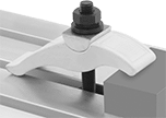
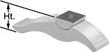
Eliminating the need for step blocks or other rear support, the pivoting rocker clamps workpieces of various thicknesses. Use these clamps with T-slot nuts or bolts to secure a workpiece, vise, or fixture to a machine table.
![]() For technical drawings and 3-D models, click on a part number.
For technical drawings and 3-D models, click on a part number.
| For Max. Workpiece Thick. | For Stud Dia. | Lg. | Wd. | Ht. | Material | Each | |
| 1" | 3/8" | 3" | 1 1/8" | 1 1/4" | Iron | 00000000 | 000000 |
| 1 1/4" | 3/8" | 3 3/4" | 1 1/8" | 1 1/4" | Iron | 00000000 | 00000 |
| 1 3/4" | 1/2" | 4 1/4" | 1 1/2" | 1 1/2" | Iron | 00000000 | 00000 |
| 2 1/2" | 1/2" | 5 3/4" | 1 1/2" | 1 1/2" | Iron | 00000000 | 00000 |
| 2 3/4" | 5/8" | 5 1/2" | 1 3/4" | 1 5/8" | Iron | 00000000 | 00000 |
| 3" | 1" | 9" | 2 7/8" | 3 3/8" | Iron | 00000000 | 000000 |
| 3 1/2" | 5/8" | 6 3/4" | 1 3/4" | 1 5/8" | Iron | 00000000 | 00000 |
| 3 1/2" | 3/4" | 7" | 2 1/8" | 2 1/4" | Iron | 00000000 | 00000 |
| 5" | 3/4" | 9" | 2 1/8" | 2 1/4" | Iron | 00000000 | 00000 |
| 5" | 1" | 11 1/8" | 2 7/8" | 3 3/8" | Iron | 00000000 | 000000 |
Heavy Duty Corner Clamps
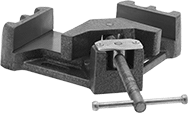
With five times the capacity of standard corner clamps, these secure two workpieces at a 90° angle. They have a pivoting clamping surface to hold materials of unequal thicknesses simultaneously. The screw is copper plated to resist weld spatter.
![]() For technical drawings and 3-D models, click on a part number.
For technical drawings and 3-D models, click on a part number.
Three-Axis Corner Clamps
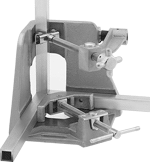
Clamp up to three workpieces at 90° angles. Press a button to move the threaded holding screws in or out. The third axis clamping arm swings out of the way for material removal. The screws are copper plated to resist weld spatter.
![]() For technical drawings and 3-D models, click on a part number.
For technical drawings and 3-D models, click on a part number.
Opening | Fixed Clamping Surface | Mounting Slots | ||||||||
|---|---|---|---|---|---|---|---|---|---|---|
| Max. | Min. | Holding Capacity, lbs. | Ht. | Material | Number of | Lg. | Wd. | Mounting Fasteners Included | Each | |
| 3 3/4" | 0" | 550 | 1 3/8" | Iron | 2 | 1 1/2" | 7/16" | No | 0000000 | 0000000 |
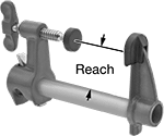
Any-Length Bar Clamps
Place the arms on a pipe that is threaded at one end and at least 12" long to create your own bar clamp. Turn the handle to tighten. The clamping surfaces have removable plastic pads that prevent damage to material. These are also known as pipe clamps.
![]() For technical drawings and 3-D models, click on a part number.
For technical drawings and 3-D models, click on a part number.
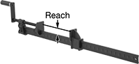
Tight-Clearance Any-Length Bar Clamps
All adjustments can be made from one end, allowing clamping in tight spaces. Place the arms on a pipe that is threaded at one end and at least 12" long to create your own bar clamp. The clamping surfaces have removable plastic pads that prevent damage to material. These are also known as pipe clamps.
![]() For technical drawings and 3-D models, click on a part number.
For technical drawings and 3-D models, click on a part number.
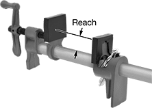
Heavy Duty Bar Clamps
Hold up to five times the capacity of standard bar clamps. Pull the lever to slide the clamping arm along the bar; release to lock in place. Use the handle for final tightening. These are also known as I-beam clamps.
![]() For technical drawings and 3-D models, click on a part number.
For technical drawings and 3-D models, click on a part number.
Bar Clamps
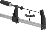
Pull the lever to slide the clamping arm along the bar; release to lock in place. Use the handle for final tightening.
![]() For technical drawings and 3-D models, click on a part number.
For technical drawings and 3-D models, click on a part number.
Opening | ||||||
|---|---|---|---|---|---|---|
| Max. | Min. | Reach | Holding Capacity, lbs. | Body Material | Each | |
| 6" | 0" | 3" | 1,200 | Iron | 0000000 | 000000 |
Fixturing Tables
Add components such as clamps, brackets, stops, rests, mounting plates, fixturing squares, risers, and V-blocks to build fixtures for welding and assembly.
![]() For technical drawings and 3-D models, click on a part number.
For technical drawings and 3-D models, click on a part number.
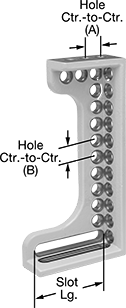
Fixturing squares elevate workpieces or position clamps and other fixture components. Use them individually or stack multiple.
Slots | Holes | Tolerance | ||||||||||||||
|---|---|---|---|---|---|---|---|---|---|---|---|---|---|---|---|---|
| Lg. | Wd. | Ht. | No. of | Lg. | Wd. | Plate Thick. | No. of | Dia. | Ctr.-to-Ctr. (A) | Ctr.-to-Ctr. (B) | Wt., lbs. | Squareness per 4" | Parallel | Material | Each | |
| 6" | 2" | 12" | 2 | 4" | 5/8" | 15/32" | 26 | 5/8" | 1" | 1" | 6.4 | 0.002" | 0.006" | Iron | 0000000 | 0000000 |