


System of Measurement System of Measurement |
|---|
|
Width Width | Show |
|---|
|
Width Width | Hide |
|---|
Material Material |
|---|
|
|
Tolerance Rating Tolerance Rating |
|---|
|
Minimum Hardness Minimum Hardness |
|---|
|
RoHS (Restriction of Hazardous Substances) RoHS (Restriction ofHazardous Substances) |
|---|
|
REACH (Registration, Evaluation, Authorization and Restriction of Chemicals) REACH (Registration,Evaluation, Authorization and Restriction of Chemicals) |
|---|
|
DFARS (Defense Acquisition Regulations Supplement) DFARS (Defense AcquisitionRegulations Supplement) |
|---|
Specifications Met Specifications Met |
|---|
|
For Maximum Keyway Diameter Tolerance For Maximum KeywayDiameter Tolerance |
|---|
|
For Minimum Keyway Diameter Tolerance For Minimum KeywayDiameter Tolerance |
|---|
|
Finish Finish |
|---|
|
Rate of Taper Rate of Taper |
|---|
|
For Machine Table T-Slot Width For Machine TableT-Slot Width |
|---|
|
Head Height Head Height |
|---|
|
Head Length Head Length |
|---|
|
For Mounting Screw Size For Mounting Screw Size |
|---|
Woodruff Keys
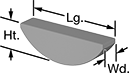

Woodruff keys work well near shaft shoulders, where a standard open keyway would create too much stress. They are also often used on tapered shafts. These keys have a rounded shape that makes them easy to remove when parts need to be taken apart frequently, such as for maintenance or prototyping. Because they're usually shorter than standard machine keys, they work best in light duty applications. Use them to connect gears and other components to shafts. Also known as half moon keys.
Steel keys offer good strength.
Inch keys conform to ANSI B17.2 standards for dimensions and tolerances.
![]() For technical drawings and 3-D models, click on a part number.
For technical drawings and 3-D models, click on a part number.
Tolerance | ||||||||||
|---|---|---|---|---|---|---|---|---|---|---|
| Woodruff Key Number | Wd. | For Keyway Dia. | Ht. | Lg. | Wd. | Ht. | Specifications Met | Pkg. Qty. | Pkg. | |
1018-1045 Carbon Steel | ||||||||||
| 23 | 5/16" | 1 3/8" | 0.584" | 1.362" | 0.000" to 0.001" | -0.006" to 0.000" | ANSI B17.2 | 10 | 000000000 | 000000 |
| 25 | 5/16" | 1 1/2" | 0.631" | 1.484" | 0.000" to 0.001" | -0.006" to 0.000" | ANSI B17.2 | 10 | 000000000 | 00000 |
| B | 5/16" | 1" | 0.428" | 0.992" | 0.000" to 0.001" | -0.006" to 0.000" | ANSI B17.2 | 25 | 000000000 | 00000 |
| C | 5/16" | 1 1/8" | 0.475" | 1.114" | 0.000" to 0.001" | -0.006" to 0.000" | ANSI B17.2 | 25 | 000000000 | 00000 |
| D | 5/16" | 1 1/4" | 0.537" | 1.24" | 0.000" to 0.001" | -0.006" to 0.000" | ANSI B17.2 | 10 | 000000000 | 00000 |
8630 Alloy Steel | ||||||||||
| 23 | 5/16" | 1 3/8" | 0.584" | 1.362" | 0.000" to 0.001" | -0.006" to 0.000" | ANSI B17.2 | 10 | 000000000 | 00000 |
| 25 | 5/16" | 1 1/2" | 0.631" | 1.484" | 0.000" to 0.001" | -0.006" to 0.000" | ANSI B17.2 | 10 | 000000000 | 00000 |
| B | 5/16" | 1" | 0.428" | 0.992" | 0.000" to 0.001" | -0.006" to 0.000" | ANSI B17.2 | 10 | 000000000 | 0000 |
| C | 5/16" | 1 1/8" | 0.475" | 1.114" | 0.000" to 0.001" | -0.006" to 0.000" | ANSI B17.2 | 10 | 000000000 | 00000 |
| D | 5/16" | 1 1/4" | 0.537" | 1.24" | 0.000" to 0.001" | -0.006" to 0.000" | ANSI B17.2 | 10 | 000000000 | 00000 |
Machine Keys

Steel keys offer good strength.
18-8 stainless steel keys offer a balance of strength and corrosion resistance. They may be mildly magnetic.
Slightly smaller than the size listed in the table, undersized keys are the choice when you need a slightly looser fit or when you have an inconsistent keyway. Use them when parts need to be taken apart frequently, such as for maintenance or prototyping.
Keys that meet ANSI B17.1 specifications conform to ANSI standards for dimensions and tolerances.
![]() For technical drawings and 3-D models, click on a part number.
For technical drawings and 3-D models, click on a part number.
Tolerance | ||||||||
|---|---|---|---|---|---|---|---|---|
| Lg. | Tolerance Rating | Ht. | Wd. | Minimum Hardness | Specifications Met | Pkg. Qty. | Pkg. | |
1008-1045 Carbon Steel | ||||||||
5/16" × 5/16" | ||||||||
| 1 1/4" | Undersized | -0.002" to 0.000" | -0.002" to 0.000" | Rockwell B50 | ANSI B17.1 Class 1 | 10 | 000000000 | 00000 |
| 1 1/2" | Undersized | -0.002" to 0.000" | -0.002" to 0.000" | Rockwell B50 | ANSI B17.1 Class 1 | 10 | 000000000 | 0000 |
| 2" | Undersized | -0.002" to 0.000" | -0.002" to 0.000" | Rockwell B50 | ANSI B17.1 Class 1 | 10 | 000000000 | 00000 |
| 2 1/2" | Undersized | -0.002" to 0.000" | -0.002" to 0.000" | Rockwell B50 | ANSI B17.1 Class 1 | 10 | 000000000 | 00000 |
18-8 Stainless Steel | ||||||||
5/16" × 5/16" | ||||||||
| 1 1/4" | Undersized | -0.002" to 0.000" | -0.002" to 0.000" | Rockwell B97 | __ | 5 | 000000000 | 0000 |
| 1 1/2" | Undersized | -0.002" to 0.000" | -0.002" to 0.000" | Rockwell B97 | __ | 5 | 000000000 | 00000 |
| 2" | Undersized | -0.002" to 0.000" | -0.002" to 0.000" | Rockwell B97 | __ | 5 | 000000000 | 00000 |
| 2 1/2" | Undersized | -0.002" to 0.000" | -0.002" to 0.000" | Rockwell B97 | __ | 5 | 000000000 | 00000 |
Tapered Gib Keys
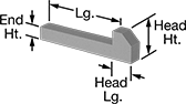
These keys have a tapered body that wedges in to the keyway for a more secure fit than standard machine keys. The gib head makes these keys easy to remove when parts need to be taken apart frequently, such as for maintenance or prototyping. Keys are tapered along their length. Use them to connect gears and other components with tapered keyways to shafts. Keys are made of steel.
The height of inch keys decreases by 1/8" for every 12" of length. They conform to ANSI B17.1 Class 1 standards for dimensions and tolerances.
![]() For technical drawings and 3-D models, click on a part number.
For technical drawings and 3-D models, click on a part number.
Tolerance | Head | ||||||||
|---|---|---|---|---|---|---|---|---|---|
| Lg. | Ht. | Wd. | Ht. | Lg. | End Ht. | Rate of Taper | Specifications Met | Each | |
1018-1045 Carbon Steel | |||||||||
5/16" × 5/16" | |||||||||
| 2" | -0.002" to 0.000" | -0.002" to 0.000" | 1/2" | 7/16" | 0.295" | 1/8" per 12" | ANSI B17.1 Class 1 | 000000000 | 00000 |
| 2 1/2" | -0.002" to 0.000" | -0.002" to 0.000" | 1/2" | 7/16" | 0.290" | 1/8" per 12" | ANSI B17.1 Class 1 | 000000000 | 0000 |
| 3" | -0.002" to 0.000" | -0.002" to 0.000" | 1/2" | 7/16" | 0.285" | 1/8" per 12" | ANSI B17.1 Class 1 | 000000000 | 0000 |
| 4" | -0.002" to 0.000" | -0.002" to 0.000" | 1/2" | 7/16" | 0.274" | 1/8" per 12" | ANSI B17.1 Class 1 | 000000000 | 0000 |
Machine Key Stock

Cut this square or rectangular key stock to length to create a straight machine key. Straight keys are the most common type of key. Machine keys are often the same material and as hard or harder than the shaft and other components with which they are used. To use a key as a sacrificial part, choose a softer key that will shear off when parts are exposed to excessive force, preventing damage to expensive equipment.
Steel key stock is an economical choice with good strength. 8630 alloy steel key stock meets ANSI B17.1 class 2 specifications for dimensions and tolerances. Zinc-plated steel key stock resists corrosion in wet environments.
Stainless steel key stock is more corrosion resistant than steel key stock. 18-8 stainless steel key stock offers a balance of strength and corrosion resistance. It may be mildly magnetic. 316 stainless steel key stock has the best corrosion resistance of our stainless steel key stock and may be mildly magnetic. 416 stainless steel key stock is stronger than other stainless key stock, and can be heat treated for extra strength. It's corrosion resistant and magnetic.
Brass key stock is corrosion resistant and nonmagnetic. Brass is softer than other metals, so it's often used for shear keys.
Aluminum key stock is one-third the weight of steel key stock, but not as strong. It resists corrosion and is nonmagnetic.
Acetal plastic and nylon 6/6 plastic key stock are slippery and wear resistant.
Slightly larger than the size listed in the table, oversized stock fits tightly in a keyway. Press it into place for use in high-torque applications or to replace a key in a worn keyway. Slightly smaller than the size listed in the table, undersized stock is the choice when you need a slightly looser fit or when you have an inconsistent keyway. Use it when parts need to be taken apart frequently, such as for maintenance or prototyping.
![]() For technical drawings and 3-D models, click on a part number.
For technical drawings and 3-D models, click on a part number.
Tolerance | ||||||
|---|---|---|---|---|---|---|
| Ht. × Wd. | Tolerance Rating | Ht. | Wd. | Minimum Hardness | Each | |
12" Lg. | ||||||
| 1/4" × 5/16" | Oversized | 0.000" to 0.003" | 0.000" to 0.003" | Rockwell B50 | 000000000 | 00000 |
| 1/4" × 5/16" | Undersized | -0.003" to 0.000" | -0.003" to 0.000" | Rockwell B50 | 000000000 | 0000 |
| 5/16" × 5/16" | Oversized | 0.000" to 0.002" | 0.000" to 0.002" | Rockwell B50 | 000000000 | 0000 |
| 5/16" × 5/16" | Undersized | -0.002" to 0.000" | -0.002" to 0.000" | Rockwell B50 | 000000000 | 0000 |
36" Lg. | ||||||
| 5/16" × 5/16" | Oversized | 0.000" to 0.002" | 0.000" to 0.002" | Rockwell B50 | 000000000 | 0000 |
| 5/16" × 5/16" | Undersized | -0.002" to 0.000" | -0.002" to 0.000" | Rockwell B50 | 000000000 | 0000 |
72" Lg. | ||||||
| 5/16" × 5/16" | Oversized | 0.000" to 0.002" | 0.000" to 0.002" | Rockwell B50 | 000000000 | 00000 |
Tolerance | ||||||
|---|---|---|---|---|---|---|
| Ht. × Wd. | Tolerance Rating | Ht. | Wd. | Minimum Hardness | Each | |
12" Lg. | ||||||
| 1/4" × 5/16" | Standard | -0.001" to 0.001" | -0.001" to 0.001" | Rockwell B90 | 000000000 | 000000 |
| 5/16" × 5/16" | Standard | -0.001" to 0.001" | -0.001" to 0.001" | Rockwell B90 | 000000000 | 0000 |
36" Lg. | ||||||
| 5/16" × 5/16" | Standard | -0.001" to 0.001" | -0.001" to 0.001" | Rockwell B90 | 000000000 | 00000 |
Tolerance | |||||||
|---|---|---|---|---|---|---|---|
| Ht. × Wd. | Tolerance Rating | Ht. | Wd. | Minimum Hardness | Specifications Met | Each | |
12" Lg. | |||||||
| 5/16" × 5/16" | Oversized | 0.000" to 0.001" | 0.000" to 0.001" | Rockwell B50 | ANSI B17.1 Class 2 | 000000000 | 00000 |
Tolerance | ||||||
|---|---|---|---|---|---|---|
| Ht. × Wd. | Tolerance Rating | Ht. | Wd. | Minimum Hardness | Each | |
12" Lg. | ||||||
| 3/16" × 5/16" | Oversized | 0.000" to 0.003" | 0.000" to 0.003" | Rockwell B50 | 000000000 | 00000 |
| 3/16" × 5/16" | Undersized | -0.003" to 0.000" | -0.003" to 0.000" | Rockwell B50 | 000000000 | 0000 |
| 1/4" × 5/16" | Oversized | 0.000" to 0.003" | 0.000" to 0.003" | Rockwell B50 | 000000000 | 0000 |
| 1/4" × 5/16" | Undersized | -0.003" to 0.000" | -0.003" to 0.000" | Rockwell B50 | 000000000 | 0000 |
| 5/16" × 5/16" | Oversized | 0.000" to 0.002" | 0.000" to 0.002" | Rockwell B50 | 000000000 | 0000 |
| 5/16" × 5/16" | Undersized | -0.002" to 0.000" | -0.002" to 0.000" | Rockwell B50 | 000000000 | 0000 |
36" Lg. | ||||||
| 5/16" × 5/16" | Oversized | 0.000" to 0.002" | 0.000" to 0.002" | Rockwell B50 | 000000000 | 0000 |
| 5/16" × 5/16" | Undersized | -0.002" to 0.000" | -0.002" to 0.000" | Rockwell B50 | 000000000 | 00000 |
Tolerance | ||||||
|---|---|---|---|---|---|---|
| Ht. × Wd. | Tolerance Rating | Ht. | Wd. | Minimum Hardness | Each | |
12" Lg. | ||||||
| 5/16" × 5/16" | Oversized | 0.000" to 0.003" | 0.000" to 0.003" | Rockwell B82 | 000000000 | 00000 |
| 5/16" × 5/16" | Undersized | -0.003" to 0.000" | -0.003" to 0.000" | Rockwell B82 | 000000000 | 00000 |
36" Lg. | ||||||
| 5/16" × 5/16" | Oversized | 0.000" to 0.003" | 0.000" to 0.003" | Rockwell B82 | 000000000 | 00000 |
| 5/16" × 5/16" | Undersized | -0.003" to 0.000" | -0.003" to 0.000" | Rockwell B82 | 000000000 | 00000 |
Tolerance | ||||||
|---|---|---|---|---|---|---|
| Ht. × Wd. | Tolerance Rating | Ht. | Wd. | Minimum Hardness | Each | |
12" Lg. | ||||||
| 1/4" × 5/16" | Undersized | -0.003" to 0.000" | -0.003" to 0.000" | Rockwell B86 | 000000000 | 000000 |
| 5/16" × 5/16" | Undersized | -0.003" to 0.000" | -0.003" to 0.000" | Rockwell B86 | 000000000 | 00000 |
36" Lg. | ||||||
| 5/16" × 5/16" | Undersized | -0.003" to 0.000" | -0.003" to 0.000" | Rockwell B86 | 000000000 | 00000 |
Tolerance | ||||||
|---|---|---|---|---|---|---|
| Ht. × Wd. | Tolerance Rating | Ht. | Wd. | Minimum Hardness | Each | |
12" Lg. | ||||||
| 5/16" × 5/16" | Undersized | -0.003" to 0.000" | -0.003" to 0.000" | Rockwell B86 | 000000000 | 000000 |
Tolerance | ||||||
|---|---|---|---|---|---|---|
| Ht. × Wd. | Tolerance Rating | Ht. | Wd. | Minimum Hardness | Each | |
12" Lg. | ||||||
| 5/16" × 5/16" | Standard | -0.008" to 0.008" | -0.008" to 0.008" | Rockwell B95 | 000000000 | 000000 |
Tolerance | ||||||
|---|---|---|---|---|---|---|
| Ht. × Wd. | Tolerance Rating | Ht. | Wd. | Minimum Hardness | Each | |
12" Lg. | ||||||
| 5/16" × 5/16" | Undersized | -0.003" to 0.000" | -0.003" to 0.000" | Durometer 80D | 000000000 | 000000 |
Fixture Keys
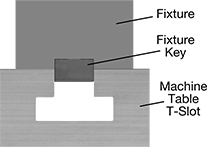
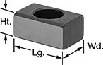
Sized to fit with precision in machine table T-slots, use these keys to locate fixtures and vises on your machine table. They mount to the underside of your fixture or vise with a socket head cap screw.
![]() For technical drawings and 3-D models, click on a part number.
For technical drawings and 3-D models, click on a part number.
| For Machine Table T-Slot Wd. | Lg. | Wd. | Ht. | Wd. Tolerance | For Mounting Screw Size | Mounting Fasteners Included | Material | Each | |
Rectangular | |||||||||
|---|---|---|---|---|---|---|---|---|---|
| 5/16" | 3/4" | 5/16" | 1/2" | -0.0005" to 0" | No. 4 | No | Steel | 0000000 | 00000 |