


Position Designation Position Designation |
|---|
|
|
Wire Connection Type Wire Connection Type |
|---|
| Quick- Disconnect Terminals | |
| Solder | |
| Wire Leads | |
Switch Action Switch Action |
|---|
|
Switch Starting Position Switch Starting Position |
|---|
Specifications Met Specifications Met |
|---|
|
Light Technology Light Technology |
|---|
|
RoHS (Restriction of Hazardous Substances) RoHS (Restriction ofHazardous Substances) |
|---|
|
REACH (Registration, Evaluation, Authorization and Restriction of Chemicals) REACH (Registration,Evaluation, Authorization and Restriction of Chemicals) |
|---|
|
Choosing an Electrical Switch
More
Rocker Switches
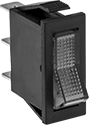

Illuminated two-position switches light up when the power is switched on.
Illuminated three-position switches stay lit regardless of switch position.
Note: Illuminated switches include a bulb. If wiring the switch and the bulb to the same circuit, the circuit voltage must not exceed bulb voltage.
![]() For technical drawings and 3-D models, click on a part number.
For technical drawings and 3-D models, click on a part number.
| No. of Circuits Controlled | Switch Starting Position | Switch Action | No. of Terminals | Industry Designation | Position Designation | Switching Current @ Voltage | Max. Voltage | Bulb Voltage | Quick-Disconnect Tab Wd. | Bulb Type | Choose a Color | Each | |
2 Position with Quick-Disconnect Terminals—Illuminated | |||||||||||||
|---|---|---|---|---|---|---|---|---|---|---|---|---|---|
For 1 7/32" Ht.×7/16" Wd. Panel Cutout | |||||||||||||
| 1 | 1 Off (Normally Open) | Stays Switched (Maintained) | 3 | SPST-NO | On-Off | 20 A @ 125 V AC | 125V AC | 125V AC | 0.25" | Neon | 0000000 | 00000 | |
For 1 7/32" Ht.×7/8" Wd. Panel Cutout | |||||||||||||
| 2 | 2 Off (Normally Open) | Stays Switched (Maintained) | 4 | DPST-NO | On-Off | 20 A @ 125 V AC | 125V AC | 125V AC | 0.25" | Neon | 0000000 | 00000 | |
3 Position with Solder Lugs—Illuminated | |||||||||||||
For 3/4" Ht.×3/4" Wd. Panel Cutout | |||||||||||||
| 2 | 2 Off (Normally Open) or 2 On (Normally Closed) | Stays Switched (Maintained) | 6 | DPDT | On-Off-On | 5 A @ 125 V AC, 3 A @ 28 V DC | 30V DC 250V AC | 110V AC | __ | Neon | White | 0000000 | 00000 |
| 2 | 2 Off (Normally Open) or 2 On (Normally Closed) | Springs Back (Momentary) | 6 | DPDT | (On)-Off-(On) | 5 A @ 125 V AC, 3 A @ 28 V DC | 30V DC 250V AC | 110V AC | __ | Neon | White | 0000000 | 00000 |
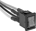
Design-Your-Own Rocker Switches
Choose from a variety of messages and colored lenses to combine a rocker with a base for a complete switch.
Bases with an on-on position designation alternate power between sets of terminals.
Optional wiring sockets make it easier to align wires and must be used with the compatible female quick-disconnect terminals listed.
Note: Illuminated switches include a bulb. If wiring the switch and the bulb to the same circuit, the circuit voltage must not exceed bulb voltage.
![]() For technical drawings and 3-D models, click on a part number.
For technical drawings and 3-D models, click on a part number.
| No. of Positions | Position Illuminated | No. of Circuits Controlled | Switch Starting Position | Switch Action | No. of Terminals | Industry Designation | Position Designation | Color | Switching Current @ Voltage | Max. Voltage | Bulb Voltage | Quick-Disconnect Tab Wd. | Each | |
| 2 | Top | 1 | 1 Off (Normally Open) | Stays Switched (Maintained) | 4 | SPST-NO | On-Off | Black | 15 A @ 125 V AC, 15 A @ 28 V DC | 30V DC 250V AC | 14V DC | 0.25" | 0000000 | 000000 |
| 2 | Top | 2 | 2 Off (Normally Open) | Stays Switched (Maintained) | 6 | DPST-NO | On-Off | Black | 15 A @ 125 V AC, 15 A @ 28 V DC | 30V DC 250V AC | 14V DC | 0.25" | 0000000 | 00000 |
| 2 | Top/Bottom | 1 | 1 Off (Normally Open) | Stays Switched (Maintained) | 6 | SPST-NO | On-Off | Black | 15 A @ 125 V AC, 15 A @ 28 V DC | 30V DC 250V AC | 14V DC | 0.25" | 0000000 | 00000 |
| 2 | Top/Bottom | 1 | 1 Off (Normally Open) or 1 On (Normally Closed) | Stays Switched (Maintained) | 7 | SPDT | On-On | Black | 15 A @ 125 V AC, 15 A @ 28 V DC | 30V DC 250V AC | 14V DC | 0.25" | 0000000 | 00000 |
| 2 | Top/Bottom | 2 | 2 Off (Normally Open) | Stays Switched (Maintained) | 8 | DPST-NO | On-Off | Black | 15 A @ 125 V AC, 15 A @ 28 V DC | 30V DC 250V AC | 14V DC | 0.25" | 0000000 | 00000 |
| 2 | Top/Bottom | 2 | 2 Off (Normally Open) or 2 On (Normally Closed) | Stays Switched (Maintained) | 10 | DPDT | On-On | Black | 15 A @ 125 V AC, 15 A @ 28 V DC | 30V DC 250V AC | 14V DC | 0.25" | 0000000 | 00000 |
| 3 | Top/Bottom | 1 | 1 Off (Normally Open) or 1 On (Normally Closed) | Stays Switched (Maintained) | 7 | SPDT | On-Off-On | Black | 15 A @ 125 V AC, 15 A @ 28 V DC | 30V DC 250V AC | 14V DC | 0.25" | 0000000 | 00000 |
| 3 | Top/Bottom | 1 | 1 Off (Normally Open) or 1 On (Normally Closed) | Springs Back (Momentary) | 7 | SPDT | (On)-Off-(On) | Black | 15 A @ 125 V AC, 15 A @ 28 V DC | 30V DC 250V AC | 14V DC | 0.25" | 0000000 | 00000 |
| 3 | Top/Bottom | 2 | 2 Off (Normally Open) or 2 On (Normally Closed) | Stays Switched (Maintained) | 10 | DPDT | On-Off-On | Black | 15 A @ 125 V AC, 15 A @ 28 V DC | 30V DC 250V AC | 14V DC | 0.25" | 0000000 | 00000 |
| 3 | Top/Bottom | 2 | 2 Off (Normally Open) or 2 On (Normally Closed) | Springs Back (Momentary) | 10 | DPDT | (On)-Off-(On) | Black | 15 A @ 125 V AC, 15 A @ 28 V DC | 30V DC 250V AC | 14V DC | 0.25" | 0000000 | 00000 |


| Compatible with Manufacturer/Model No. | Each | |
| AMP 42100-2, Packard 12015870 | 00000000 | 00000 |
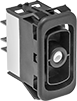
Miniature Rocker Switches

Maximize space in a panel—these switches are smaller than most standard rocker switches.
Note: Illuminated switches include a bulb. If wiring the switch and the bulb to the same circuit, the circuit voltage must not exceed bulb voltage.
![]() For technical drawings and 3-D models, click on a part number.
For technical drawings and 3-D models, click on a part number.
Wire Leads | |||||||||||||||
|---|---|---|---|---|---|---|---|---|---|---|---|---|---|---|---|
| No. of Circuits Controlled | Switch Starting Position | Switch Action | No. of Terminals | Industry Designation | Position Designation | Switching Current @ Voltage | Max. Voltage | Bulb Voltage | No. of | Lg. | Quick-Disconnect Tab Wd. | Bulb Type | Choose a Color | Each | |
2 Position with Quick-Disconnect Terminals—Illuminated | |||||||||||||||
For 3/4" Ht.×1/2" Wd. Panel Cutout | |||||||||||||||
| 2 | 2 Off (Normally Open) | Stays Switched (Maintained) | 4 | DPST-NO | On-Off | 9 A @ 125 V AC | 125V AC | 125V AC | __ | __ | 0.187" | Neon | 0000000 | 00000 | |
2 Position with Wire Leads—Illuminated | |||||||||||||||
For 3/4" Ht.×1/2" Wd. Panel Cutout | |||||||||||||||
| 2 | 2 Off (Normally Open) | Stays Switched (Maintained) | 4 | DPST-NO | On-Off | 9 A @ 125 V AC | 125V AC | 125V AC | 4 | 12" | __ | Neon | Green | 00000000 | 00000 |
| 2 | 2 Off (Normally Open) | Stays Switched (Maintained) | 4 | DPST-NO | On-Off | 9 A @ 125 V AC | 125V AC | 125V AC | 4 | 12" | __ | Neon | Red | 00000000 | 00000 |
| 2 | 2 Off (Normally Open) | Stays Switched (Maintained) | 4 | DPST-NO | On-Off | 9 A @ 125 V AC | 125V AC | 125V AC | 4 | 12" | __ | Neon | Yellow | 00000000 | 00000 |
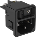
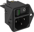
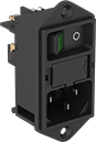
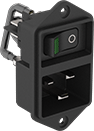
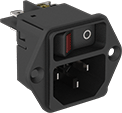
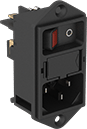
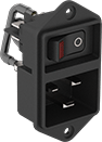
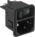
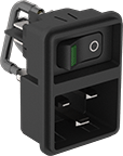
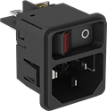
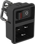
IEC Connectors with Power Switch
Switch your device on and off without needing a separate switch. These connectors work with industry standard cords often found on power supplies, appliances, and other electronic devices. Wire these connectors using the quick-disconnect terminals. They slide together with mating terminals for a secure hold that's also easy to pull apart to make repairs. The terminals are on the back of the connector, so the wiring stays inside your device.
Class I shock protection means they have insulation and a protective ground. They meet UL 94 V-0, so they self-extinguish within 10 seconds if they catch fire and won’t spread the fire by dripping. They’re also UL and C-UL recognized components, CE and ENEC marked, and CSA certified—they meet U.S., Canadian, and European safety standards.
Drill mounting holes in your device to mount screw-on connectors to housings of any thickness. Snap-in connectors secure with tabs. They do not require fasteners, but they do need a specific panel thickness on your device housing and a precisely cut hole for secure mounting.
The power switch on connectors with an indicator light illuminates when your device is on.
Connectors for 20 mm-long fuses have a drawer to hold a fuse (sold separately), which prevents short circuits and circuit overloads from damaging your device.
![]() For technical drawings and 3-D models, click on a part number.
For technical drawings and 3-D models, click on a part number.

For Panel Cutout | ||||||||||||
|---|---|---|---|---|---|---|---|---|---|---|---|---|
| IEC Style | Voltage | Current (Rating) | No. of Circuits Controlled | Switch Starting Position | Industry Designation | Ht. | Wd. | For Panel Thick. | Temp. Range, °F | Environmental Rating | Each | |
Snap In | ||||||||||||
| C14 | 250V AC | 15A (UL), 10A (IEC) | 1 | 1 Off (Normally Open) | SPST-NO | 1.24" | 1.09" | 0.098" | -10° to 155° | IP40 | 00000000 | 000000 |
with Green Indicator Light
and Fuse Circuit Protection
Receptacle with
Green Indicator Light
with Red Indicator Light
and Fuse Circuit Protection
C20 Receptacle
with Red Indicator Light
Receptacle with
Green Indicator Light
For Fuse | For Panel Cutout | |||||||||||||
|---|---|---|---|---|---|---|---|---|---|---|---|---|---|---|
| IEC Style | Voltage | Current (Rating) | No. of Circuits Controlled | Switch Starting Position | Industry Designation | O'all Dia., mm | O'all Lg., mm | Ht. | Wd. | For Panel Thick. | Temp. Range, °F | Environmental Rating | Each | |
Green Indicator | ||||||||||||||
Screw On | ||||||||||||||
| C14 | 250V AC | 10A (UL), 10A (IEC) | 2 | 2 Off (Normally Open) | DPST-NO | 5 | 20 | 1.11" | 1.85" | 0.314" | -10° to 185° | IP40 | 0000000 | 000000 |
| C14 | 250V AC | 15A (UL), 10A (IEC) | __ | 2 Off (Normally Open) | DPST-NO | __ | __ | 1.24" | 1.09" | 0.24" | -10° to 155° | IP40 | 00000000 | 00000 |
| C20 | 250V AC | 20A (UL), 16A (IEC) | 2 | 2 Off (Normally Open) | DPST-NO | __ | __ | 1.83" | 1.28" | 0.314" | -10° to 155° | IP40 | 00000000 | 00000 |
Snap In | ||||||||||||||
| C14 | 250V AC | 15A (UL), 10A (IEC) | 2 | 2 Off (Normally Open) | DPST-NO | __ | __ | 1.24" | 1.09" | 0.059" | -10° to 155° | IP40 | 00000000 | 00000 |
| C14 | 250V AC | 15A (UL), 10A (IEC) | 2 | 2 Off (Normally Open) | DPST-NO | __ | __ | 1.24" | 1.09" | 0.098" | -10° to 155° | IP40 | 00000000 | 00000 |
| C20 | 250V AC | 20A (UL), 16A (IEC) | 2 | 2 Off (Normally Open) | DPST-NO | __ | __ | 1.83" | 1.28" | 0.059" | -10° to 155° | IP40 | 00000000 | 00000 |
| C20 | 250V AC | 20A (UL), 16A (IEC) | 2 | 2 Off (Normally Open) | DPST-NO | __ | __ | 1.83" | 1.28" | 0.098" | -10° to 155° | IP40 | 00000000 | 00000 |
Red Indicator | ||||||||||||||
Screw On | ||||||||||||||
| C14 | 250V AC | 10A (UL), 10A (IEC) | 2 | 2 Off (Normally Open) | DPST-NO | 5 | 20 | 1.11" | 1.85" | 0.314" | -10° to 185° | IP40 | 0000000 | 00000 |
| C14 | 250V AC | 15A (UL), 10A (IEC) | __ | 2 Off (Normally Open) | DPST-NO | __ | __ | 1.24" | 1.09" | 0.24" | -10° to 155° | IP40 | 00000000 | 00000 |
| C20 | 250V AC | 20A (UL), 16A (IEC) | 2 | 2 Off (Normally Open) | DPST-NO | __ | __ | 1.83" | 1.28" | 0.314" | -10° to 155° | IP40 | 00000000 | 00000 |
Snap In | ||||||||||||||
| C14 | 250V AC | 15A (UL), 10A (IEC) | 2 | 2 Off (Normally Open) | DPST-NO | __ | __ | 1.24" | 1.09" | 0.059" | -10° to 155° | IP40 | 00000000 | 00000 |
| C14 | 250V AC | 15A (UL), 10A (IEC) | 2 | 2 Off (Normally Open) | DPST-NO | __ | __ | 1.24" | 1.09" | 0.098" | -10° to 155° | IP40 | 00000000 | 00000 |
| C20 | 250V AC | 20A (UL), 16A (IEC) | 2 | 2 Off (Normally Open) | DPST-NO | __ | __ | 1.83" | 1.28" | 0.059" | -10° to 155° | IP40 | 00000000 | 00000 |
| C20 | 250V AC | 20A (UL), 16A (IEC) | 2 | 2 Off (Normally Open) | DPST-NO | __ | __ | 1.83" | 1.28" | 0.098" | -10° to 155° | IP40 | 00000000 | 00000 |
For Fuse | ||||
|---|---|---|---|---|
| For No. of Fuses | O'all Dia., mm | O'all Lg., mm | Each | |
| 2 | 5 | 20 | 00000000 | 00000 |