Filter by
Stroke Length
Dynamic Push Load Capacity

Rod End Type
Dynamic Pull Load Capacity
Environment
Static Load Capacity
Duty Cycle
Maximum Speed
Stroke Protection Type
Overall Height
Extension Rod Type
Rod End Location
Export Control Classification Number (ECCN)
DFARS Specialty Metals
Rod Diameter
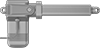
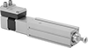
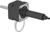
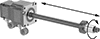
Electric Actuators

Other Products