


Filter by
Product Family
Voltage
Power
Maximum Flow Rate @ Pressure

Vacuum Rating
Full Load Current @ Voltage
Airflow @ Static Pressure
Overall Width
Maximum Pressure
Housing Material
DFARS Specialty Metals
Export Control Classification Number (ECCN)
High-Flow Low-Pressure Compressed Air Blowers
Single Stage
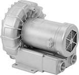 |
Single-stage blowers circulate air once and then exhaust.
Inverter Rated—Inverter-rated blowers have a motor that can run at slow speeds without overheating, so they can be used with a motor speed control (variable frequency drive).
Blowers | Air Intake Filters | Valves | |||||||||||||||||
|---|---|---|---|---|---|---|---|---|---|---|---|---|---|---|---|---|---|---|---|
Overall | Pipe Size | ||||||||||||||||||
Max. Pressure | Max. Flow Rate @ Pressure | Vacuum Rating | Power, hp | Full Load Current @ Voltage | Volume (Sound) | Lg. | Wd. | Ht. | Temp. Range, ° F | Inlet | Outlet | Each | Each | Each | |||||
Single Phase, 120/208/230V AC | |||||||||||||||||||
NPT Female Inlet and Outlet | |||||||||||||||||||
| 1 psi 29 in. H₂O | 27 ft³/min @ 0 psi | 1.9 in. Hg 27 in. H₂O | 1/8 | 2.3 amp @ 115V AC 1.2 amp @ 208V AC 1.2 amp @ 230V AC | 57 dBA | 9" | 8" | 9" | 32 to 100 | 1 | 1 | 9960K51 | 0000000 | 9960K823 | 0000000 | 9960K821 | 0000000 | ||
| 1 psi 39 in. H₂O | 42 ft³/min @ 0 psi | 2.6 in. Hg 35 in. H₂O | 1/3 | 3.8 amp @ 115V AC 2 amp @ 208V AC 1.9 amp @ 230V AC | 63 dBA | 10" | 9" | 9" | 32 to 100 | 1 | 1 | 9960K52 | 00000000 | 9960K823 | 000000 | 9960K821 | 000000 | ||
| 1 psi 52 in. H₂O | 156 ft³/min @ 0 psi | 3.8 in. Hg 51 in. H₂O | 2 | 19.7 amp @ 115V AC 10.6 amp @ 208V AC 9.9 amp @ 230V AC | 71 dB | 14" | 13" | 14" | 5 to 100 | 2 | 2 | 4393K51 | 00000000 | ——— | 0 | 4393K41 | 000000 | ||
| 2 psi 42 in. H₂O | 52 ft³/min @ 0 psi | 3 in. Hg 40 in. H₂O | 1/2 | 6 amp @ 115V AC 3.2 amp @ 208V AC 3 amp @ 230V AC | 68 dBA | 13" | 10" | 10" | 32 to 100 | 1 1/4 | 1 1/4 | 9960K54 | 00000000 | 9960K824 | 000000 | 9960K821 | 000000 | ||
| 2 psi 52 in. H₂O | 92 ft³/min @ 0 psi | 3.5 in. Hg 48 in. H₂O | 1 | 9.8 amp @ 115V AC 5.2 amp @ 208V AC 4.9 amp @ 230V AC | 68 dBA | 13" | 11" | 12" | 32 to 100 | 1 1/2 | 1 1/2 | 9960K57 | 00000000 | 9960K825 | 000000 | 9960K821 | 000000 | ||
| 2 psi 65 in. H₂O | 127 ft³/min @ 0 psi | 4.4 in. Hg 60 in. H₂O | 1 1/2 | 17.5 amp @ 115V AC 10 amp @ 208V AC 9 amp @ 230V AC | 74 dBA | 16" | 13" | 14" | 32 to 100 | 1 1/2 | 1 1/2 | 9960K58 | 00000000 | 9960K825 | 000000 | 9960K821 | 000000 | ||
Single Phase, 120/230V AC (Not Inverter Rated) | |||||||||||||||||||
BSPP Female Inlet and Outlet | |||||||||||||||||||
| 2 psi 56 in. H₂O | 57 ft³/min @ 0 psi | 3.8 in. Hg 52 in. H₂O | 1/2 | 7 amp @ 115V AC 3.4 amp @ 230V AC | 56 dBA | 10" | 10" | 10" | 5 to 100 | 1 1/4 | 1 1/4 | 1010K41 | 00000000 | ——— | 0 | ——— | 0 | ||
| 3 psi 76 in. H₂O | 102 ft³/min @ 0 psi | 5.3 in. Hg 72 in. H₂O | 1 1/2 | 16 amp @ 115V AC 8 amp @ 230V AC | 64 dBA | 12" | 11" | 12" | 5 to 100 | 1 1/2 | 1 1/2 | 1010K42 | 00000000 | ——— | 0 | ——— | 0 | ||
Three Phase, 190/230/380/460V AC (Inverter Rated) | |||||||||||||||||||
NPT Female Inlet and Outlet | |||||||||||||||||||
| 2 psi 56 in. H₂O | 103 ft³/min @ 0 psi | 4.1 in. Hg 56 in. H₂O | 1 | 4.4 amp @ 190V AC 3.7 amp @ 230V AC 2.2 amp @ 380V AC 2.1 amp @ 460V AC | 64 dBA | 11" | 11" | 12" | 32 to 100 | 1 1/2 | 1 1/2 | 1010K35 | 00000000 | ——— | 0 | ——— | 0 | ||
| 3 psi 79 in. H₂O | 150 ft³/min @ 0 psi | 6.5 in. Hg 88 in. H₂O | 2 3/4 | 7.5 amp @ 190V AC 7.3 amp @ 230V AC 4.3 amp @ 380V AC 4.4 amp @ 460V AC | 70 dBA | 14" | 13" | 15" | 32 to 100 | 2 | 2 | 1010K36 | 00000000 | ——— | 0 | ——— | 0 | ||
| 3 psi 92 in. H₂O | 221 ft³/min @ 0 psi | 7.1 in. Hg 96 in. H₂O | 4 1/2 | 12.5 amp @ 190V AC 12.6 amp @ 230V AC 7.2 amp @ 380V AC 7.3 amp @ 460V AC | 72 dBA | 15" | 15" | 17" | 32 to 100 | 2 | 2 | 1010K38 | 00000000 | ——— | 0 | ——— | 0 | ||
| 4 psi 116 in. H₂O | 150 ft³/min @ 0 psi | 7.7 in. Hg 104 in. H₂O | 3 1/4 | 9.7 amp @ 190V AC 10.3 amp @ 230V AC 5.6 amp @ 380V AC 6 amp @ 460V AC | 70 dBA | 14" | 13" | 15" | 32 to 100 | 2 | 2 | 1010K37 | 00000000 | ——— | 0 | ——— | 0 | ||
Three Phase, 208/230/460V AC | |||||||||||||||||||
NPT Female Inlet and Outlet | |||||||||||||||||||
| 2 psi 43 in. H₂O | 53 ft³/min @ 0 psi | 2.9 in. Hg 40 in. H₂O | 1/2 | 2 amp @ 208V AC 2 amp @ 230V AC 1 amp @ 460V AC | 68 dBA | 11" | 10" | 10" | 32 to 100 | 1 1/4 | 1 1/4 | 9960K45 | 00000000 | 9960K824 | 000000 | 9960K821 | 000000 | ||
| 2 psi 52 in. H₂O | 92 ft³/min @ 0 psi | 3.5 in. Hg 48 in. H₂O | 1 | 3.4 amp @ 208V AC 3.2 amp @ 230V AC 1.6 amp @ 460V AC | 68 dBA | 13" | 11" | 12" | 32 to 100 | 1 1/2 | 1 1/2 | 9960K56 | 00000000 | 9960K825 | 000000 | 9960K821 | 000000 | ||
| 2 psi 65 in. H₂O | 127 ft³/min @ 0 psi | 4.4 in. Hg 60 in. H₂O | 1 1/2 | 5.1 amp @ 208V AC 4.9 amp @ 230V AC 2.5 amp @ 460V AC | 74 dBA | 14" | 13" | 14" | 32 to 100 | 1 1/2 | 1 1/2 | 9960K59 | 00000000 | 9960K825 | 000000 | 9960K821 | 000000 | ||
| 2 psi 65 in. H₂O | 160 ft³/min @ 0 psi | 4.4 in. Hg 60 in. H₂O | 2 1/2 | 6.6 amp @ 208V AC 6.2 amp @ 230V AC 3.1 amp @ 460V AC | 75 dBA | 15" | 14" | 14" | 32 to 100 | 1 1/2 | 1 1/2 | 9960K62 | 00000000 | ——— | 0 | ——— | 0 | ||
Three Phase, 208/230/460V AC (Inverter Rated) | |||||||||||||||||||
NPT Female Inlet and Outlet | |||||||||||||||||||
| 1 psi 52 in. H₂O | 156 ft³/min @ 0 psi | 3.8 in. Hg 51 in. H₂O | 2 | 5.7 amp @ 208V AC 5.7 amp @ 230V AC 2.8 amp @ 460V AC | 71 dB | 14" | 13" | 14" | 5 to 100 | 2 | 2 | 4393K52 | 00000000 | ——— | 0 | 4393K41 | 000000 | ||
| 2 psi 80 in. H₂O | 156 ft³/min @ 0 psi | 6.6 in. Hg 89 in. H₂O | 3 | 8.2 amp @ 208V AC 8.3 amp @ 230V AC 4.1 amp @ 460V AC | 71 dB | 14" | 13" | 14" | 5 to 100 | 2 | 2 | 4393K53 | 00000000 | ——— | 0 | 4393K41 | 000000 | ||
| 3 psi 110 in. H₂O | 216 ft³/min @ 0 psi | 8.1 in. Hg 110 in. H₂O | 5 1/2 | 14.6 amp @ 208V AC 15.1 amp @ 230V AC 7.5 amp @ 460V AC | 74 dB | 15" | 15" | 15" | 5 to 100 | 2 | 2 | 4393K54 | 00000000 | ——— | 0 | 4393K41 | 000000 | ||
| 4 psi 105 in. H₂O | 207 ft³/min @ 0 psi | 6.5 in. Hg 88 in. H₂O | 5 | 13 amp @ 208V AC 12 amp @ 230V AC 6 amp @ 460V AC | 72 dBA | 19" | 15" | 15" | 32 to 100 | 2 | 2 | 9960K63 | 00000000 | 9960K826 | 000000 | 9960K821 | 000000 | ||
| 4 psi 110 in. H₂O | 265 ft³/min @ 0 psi | 6.6 in. Hg 90 in. H₂O | 6 | 16 amp @ 208V AC 15 amp @ 230V AC 7.5 amp @ 460V AC | 79 dBA | 17" | 17" | 18" | 32 to 100 | 2 | 2 | 9960K64 | 00000000 | 9960K826 | 000000 | 9960K821 | 000000 | ||
| 4 psi 110 in. H₂O | 307 ft³/min @ 0 psi | 8.9 in. Hg 121 in. H₂O | 7 1/2 | 19.8 amp @ 208V AC 19.5 amp @ 230V AC 9.7 amp @ 460V AC | 75 dBA | 22" | 18" | 19" | 5 to 100 | 3 | 3 | 4393K85 | 00000000 | ——— | 0 | 4393K41 | 000000 | ||
| 5 psi 125 in. H₂O | 420 ft³/min @ 0 psi | 8.1 in. Hg 110 in. H₂O | 10 | 35 amp @ 208V AC 29.5 amp @ 230V AC 15 amp @ 460V AC | 78 dBA | 22" | 18" | 20" | 32 to 100 | 2 1/2 | 2 1/2 | 9960K65 | 00000000 | 9960K827 | 000000 | 9960K821 | 000000 | ||
Three Phase, 220/275/380/480V AC (Inverter Rated) | |||||||||||||||||||
BSPP Female Inlet and Outlet | |||||||||||||||||||
| 2 psi 64 in. H₂O | 57 ft³/min @ 0 psi | 4.4 in. Hg 60 in. H₂O | 1/2 | 2.6 amp @ 200V AC 2.6 amp @ 275V AC 1.5 amp @ 380V AC 1.5 amp @ 480V AC | 56 dBA | 10" | 10" | 10" | 5 to 100 | 1 1/4 | 1 1/4 | 1010K24 | 00000000 | ——— | 0 | ——— | 0 | ||
Three Phase, 230/460V AC (Inverter Rated) | |||||||||||||||||||
NPT Female Inlet and Outlet | |||||||||||||||||||
| 4 psi 105 in. H₂O | 795 ft³/min @ 0 psi | 7 in. Hg 95 in. H₂O | 18 | 52 amp @ 230V AC 26 amp @ 460V AC | 79 dBA | 29" | 18" | 20" | 32 to 100 | 2 1/2 | 4 | 9960K66 | 00000000 | 9960K827 | 000000 | 9960K822 | 00000000 | ||
Two Stage
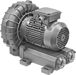 |
Two-stage blowers circulate air twice and then exhaust, creating higher pressure or vacuum than single-stage blowers with the same horsepower.
Inverter Rated—Inverter-rated blowers have a motor that can run at slow speeds without overheating, so they can be used with a motor speed control (variable frequency drive).
Blowers | Valves | ||||||||||||||||
|---|---|---|---|---|---|---|---|---|---|---|---|---|---|---|---|---|---|
Overall | Pipe Size | ||||||||||||||||
Max. Pressure | Max. Flow Rate @ Pressure | Vacuum Rating | Power, hp | Full Load Current @ Voltage | Volume (Sound) | Lg. | Wd. | Ht. | Temp. Range, ° F | Inlet | Outlet | Each | Each | ||||
Single Phase, 120/208/230V AC | |||||||||||||||||
NPT Female Inlet and Outlet | |||||||||||||||||
| 3 psi 98 in. H₂O | 35 ft³/min @ 0 psi | 7.2 in. Hg 97 in. H₂O | 3/4 | 8.3 amp @ 115V AC 4.1 amp @ 208V AC 4.2 amp @ 230V AC | 64 dB | 14" | 10" | 11" | 5 to 100 | 3/4 | 3/4 | 4393K56 | 000000000 | 4393K41 | 0000000 | ||
| 4 psi 120 in. H₂O | 35 ft³/min @ 0 psi | 8.1 in. Hg 110 in. H₂O | 1 | 9.4 amp @ 115V AC 5.5 amp @ 208V AC 5 amp @ 230V AC | 64 dB | 16" | 10" | 11" | 5 to 100 | 3/4 | 3/4 | 4393K58 | 00000000 | 4393K41 | 000000 | ||
| 5 psi 140 in. H₂O | 65 ft³/min @ 0 psi | 11.1 in. Hg 151 in. H₂O | 2 | 19.7 amp @ 115V AC 10.6 amp @ 208V AC 9.9 amp @ 230V AC | 72 dB | 15" | 13" | 14" | 5 to 100 | 1 1/4 | 1 1/4 | 4393K63 | 00000000 | 4393K41 | 000000 | ||
| 5 psi 141 in. H₂O | 81 ft³/min @ 0 psi | 11.1 in. Hg 151 in. H₂O | 3 | 29.4 amp @ 115V AC 16.6 amp @ 208V AC 14.8 amp @ 230V AC | 73 dB | 15" | 14" | 15" | 5 to 100 | 1 1/4 | 1 1/4 | 4393K65 | 00000000 | 4393K41 | 000000 | ||
| 5 psi 161 in. H₂O | 41 ft³/min @ 0 psi | 10.3 in. Hg 140 in. H₂O | 1 1/2 | 14.6 amp @ 115V AC 7.6 amp @ 208V AC 7.3 amp @ 230V AC | 69 dB | 14" | 11" | 12" | 5 to 100 | 1 1/4 | 1 1/4 | 4393K61 | 00000000 | 4393K41 | 000000 | ||
Three Phase, 208/230/460V AC (Inverter Rated) | |||||||||||||||||
NPT Female Inlet and Outlet | |||||||||||||||||
| 3 psi 98 in. H₂O | 35 ft³/min @ 0 psi | 7.2 in. Hg 97 in. H₂O | 3/4 | 2.3 amp @ 208V AC 2.2 amp @ 230V AC 1.3 amp @ 460V AC | 64 dB | 14" | 10" | 11" | 5 to 100 | 3/4 | 3/4 | 4393K57 | 00000000 | 4393K41 | 000000 | ||
| 4 psi 120 in. H₂O | 35 ft³/min @ 0 psi | 8.1 in. Hg 110 in. H₂O | 1 | 2.9 amp @ 208V AC 2.9 amp @ 230V AC 1.4 amp @ 460V AC | 64 dB | 16" | 10" | 11" | 5 to 100 | 3/4 | 3/4 | 4393K59 | 00000000 | 4393K41 | 000000 | ||
| 5 psi 140 in. H₂O | 65 ft³/min @ 0 psi | 11.1 in. Hg 151 in. H₂O | 2 | 5.8 amp @ 208V AC 5.2 amp @ 230V AC 2.8 amp @ 460V AC | 72 dBA | 16" | 13" | 14" | 5 to 100 | 1 1/4 | 1 1/4 | 4393K47 | 00000000 | 4393K41 | 000000 | ||
| 5 psi 140 in. H₂O | 147 ft³/min @ 0 psi | 11.8 in. Hg 160 in. H₂O | 5 1/2 | 14.6 amp @ 208V AC 15.1 amp @ 230V AC 7.5 amp @ 460V AC | 77 dBA | 17" | 18" | 19" | 5 to 100 | 2 | 2 | 4393K87 | 00000000 | 4393K41 | 000000 | ||
| 5 psi 141 in. H₂O | 81 ft³/min @ 0 psi | 11.1 in. Hg 151 in. H₂O | 3 | 8.3 amp @ 208V AC 7.4 amp @ 230V AC 4 amp @ 460V AC | 73 dBA | 16" | 14" | 15" | 5 to 100 | 1 1/4 | 1 1/4 | 4393K38 | 00000000 | 4393K41 | 000000 | ||
| 5 psi 161 in. H₂O | 41 ft³/min @ 0 psi | 10.3 in. Hg 140 in. H₂O | 1 1/2 | 4.3 amp @ 208V AC 4.3 amp @ 230V AC 2.1 amp @ 460V AC | 69 dB | 14" | 11" | 12" | 5 to 100 | 1 1/4 | 1 1/4 | 4393K62 | 00000000 | 4393K41 | 000000 | ||
| 6 psi 191 in. H₂O | 65 ft³/min @ 0 psi | 11.1 in. Hg 151 in. H₂O | 3 | 8.2 amp @ 208V AC 8.3 amp @ 230V AC 4.1 amp @ 460V AC | 73 dB | 15" | 13" | 14" | 5 to 100 | 1 1/4 | 1 1/4 | 4393K64 | 00000000 | 4393K41 | 000000 | ||
| 7 psi 201 in. H₂O | 81 ft³/min @ 0 psi | 11.1 in. Hg 151 in. H₂O | 4 | 10.9 amp @ 208V AC 11.1 amp @ 230V AC 5.5 amp @ 460V AC | 73 dB | 15" | 14" | 15" | 5 to 100 | 1 1/4 | 1 1/4 | 4393K66 | 00000000 | 4393K41 | 000000 | ||
| 7 psi 200 in. H₂O | 177 ft³/min @ 0 psi | 13.3 in. Hg 180 in. H₂O | 10 | 26.1 amp @ 208V AC 25 amp @ 230V AC 12.5 amp @ 460V AC | 78 dBA | 19 1/2" | 19" | 20" | 5 to 100 | 2 | 2 | 4393K89 | 00000000 | 4393K41 | 000000 | ||
| 8 psi 220 in. H₂O | 147 ft³/min @ 0 psi | 13.3 in. Hg 180 in. H₂O | 7 1/2 | 19.8 amp @ 208V AC 19.5 amp @ 230V AC 9.7 amp @ 460V AC | 78 dBA | 18" | 18" | 19" | 5 to 100 | 2 | 2 | 4393K88 | 00000000 | 4393K41 | 000000 | ||
High-Flow Low-Pressure Hazardous Location Compressed Air Blowers
Single Stage
 |
Overall | Pipe Size | |||||||||||||||
|---|---|---|---|---|---|---|---|---|---|---|---|---|---|---|---|---|
Max. Pressure | Max. Flow Rate @ Pressure | Vacuum Rating | Power, hp | Full Load Current @ Voltage | Volume (Sound), dBA | Lg. | Wd. | Ht. | Temp. Range, ° F | Inlet | Outlet | Hazardous Location Rating | Each | |||
Three Phase, 208/230/460V AC (Inverter Rated) | ||||||||||||||||
NPT Female Inlet and Outlet | ||||||||||||||||
| 2 psi 50 in. H₂O | 556 ft³/min @ 0 psi | 3.7 in. Hg 50 in. H₂O | 10 | 24.3 amp @ 208V AC 22.4 amp @ 230V AC 11.2 amp @ 460V AC | 81 | 25" | 20" | 22" | 5 to 100 | 4 | 4 | NEC Class I Divisions 1, 2 Group D NEC Class II Division 2 Groups F, G | 4393K74 | 000000000 | ||
| 2 psi 60 in. H₂O | 471 ft³/min @ 0 psi | 4.4 in. Hg 59 in. H₂O | 10 | 24.3 amp @ 208V AC 22.4 amp @ 230V AC 11.2 amp @ 460V AC | 81 | 25" | 19" | 22" | 5 to 100 | 4 | 4 | NEC Class I Divisions 1, 2 Group D NEC Class II Division 2 Groups F, G | 4393K73 | 00000000 | ||
| 2 psi 68 in. H₂O | 381 ft³/min @ 0 psi | 5 in. Hg 67 in. H₂O | 7 1/2 | 18.9 amp @ 208V AC 17.8 amp @ 230V AC 8.9 amp @ 460V AC | 80 | 23" | 18" | 19" | 5 to 100 | 3 | 3 | NEC Class I Divisions 1, 2 Group D NEC Class II Division 2 Groups F, G | 4393K72 | 00000000 | ||
| 4 psi 116 in. H₂O | 294 ft³/min @ 0 psi | 8.8 in. Hg 119 in. H₂O | 7 1/2 | 18.9 amp @ 208V AC 17.8 amp @ 230V AC 8.9 amp @ 460V AC | 80 | 23" | 16" | 19" | 5 to 100 | 3 | 3 | NEC Class I Divisions 1, 2 Group D NEC Class II Division 2 Groups F, G | 4393K71 | 00000000 | ||
Two Stage
|
Overall | Pipe Size | |||||||||||||||
|---|---|---|---|---|---|---|---|---|---|---|---|---|---|---|---|---|
Max. Pressure | Max. Flow Rate @ Pressure | Vacuum Rating | Power, hp | Full Load Current @ Voltage | Volume (Sound), dBA | Lg. | Wd. | Ht. | Temp. Range, ° F | Inlet | Outlet | Hazardous Location Rating | Each | |||
Three Phase, 208/230/460V AC (Inverter Rated) | ||||||||||||||||
NPT Female Inlet and Outlet | ||||||||||||||||
| 3 psi 110 in. H₂O | 220 ft³/min @ 0 psi | 8.1 in. Hg 110 in. H₂O | 7 1/2 | 18.9 amp @ 208V AC 17.8 amp @ 230V AC 8.9 amp @ 460V AC | 78 | 27" | 19" | 22" | 5 to 100 | 4 | 4 | NEC Class I Divisions 1, 2 Group D NEC Class II Division 2 Groups F, G | 4393K77 | 000000000 | ||
| 4 psi 115 in. H₂O | 274 ft³/min @ 0 psi | 8.5 in. Hg 115 in. H₂O | 10 | 24.3 amp @ 208V AC 22.4 amp @ 230V AC 11.2 amp @ 460V AC | 81 | 27" | 20" | 22" | 5 to 100 | 4 | 4 | NEC Class I Divisions 1, 2 Group D NEC Class II Division 2 Groups F, G | 4393K78 | 00000000 | ||
| 5 psi 150 in. H₂O | 167 ft³/min @ 0 psi | 11 in. Hg 149 in. H₂O | 7 1/2 | 18.9 amp @ 208V AC 17.8 amp @ 230V AC 8.9 amp @ 460V AC | 77 | 23" | 18" | 19" | 5 to 100 | 2 | 2 | NEC Class I Divisions 1, 2 Group D NEC Class II Division 2 Groups F, G | 4393K76 | 00000000 | ||
| 8 psi 240 in. H₂O | 128 ft³/min @ 0 psi | 11.9 in. Hg 161 in. H₂O | 7 1/2 | 18.9 amp @ 208V AC 17.8 amp @ 230V AC 8.9 amp @ 460V AC | 75 | 27" | 16" | 19" | 5 to 100 | 2 | 2 | NEC Class I Divisions 1, 2 Group D NEC Class II Division 2 Groups F, G | 4393K75 | 00000000 | ||
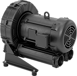
Spark-Resistant Blowers
With Round Outlet and Round Inlet—Totally Enclosed Motor Enclosure
 |
Overall | Mounting | |||||||||||||||||
|---|---|---|---|---|---|---|---|---|---|---|---|---|---|---|---|---|---|---|
Airflow @ SP | Volume (Sound) @ Distance | Motor Speed, rpm | Power, hp | Outlet Dia. | Inlet Dia. | Wheel Dia. | Ht. | Wd. | Dp. | Current | Temp. Range, ° F | Housing Material | Fasteners Included | Hole Dia. | Each | |||
120V AC/230V AC | ||||||||||||||||||
Single Phase—Hardwire | ||||||||||||||||||
| 295 ft³/min @ 1 in. H₂O 505 ft³/min @ 1/4 in. H₂O | 55 dBA @ 15 ft. | 1,750 | 1/4 | 6" | 6" | 6 1/4" | 14 1/8" | 12 1/4" | 13 1/4" | 5.0 amp/2.5 amp | 0 to 150 | Aluminum | No | 7/16" | 1955K53 | 000000000 | ||
| 320 ft³/min @ 1 in. H₂O 375 ft³/min @ 1/4 in. H₂O | 60 dBA @ 15 ft. | 3,450 | 1/3 | 4" | 5" | 4 3/4" | 12 5/8" | 9 7/8" | 12 1/4" | 6.0 amp/3.2 amp | 0 to 150 | Aluminum | No | 7/16" | 1955K52 | 00000000 | ||
| 995 ft³/min @ 1 in. H₂O 1,070 ft³/min @ 1/4 in. H₂O | 70 dBA @ 15 ft. | 3,450 | 1 1/2 | 6" | 6" | 6 1/4" | 14 1/8" | 12 1/4" | 13 1/4" | 13.2 amp/7.3 amp | 0 to 150 | Aluminum | No | 7/16" | 1955K54 | 00000000 | ||
| 1,045 ft³/min @ 1/4 in. H₂O | 55 dBA @ 15 ft. | 1,150 | 1/3 | 8" | 8" | 8 1/4" | 18 3/4" | 14 3/4" | 15 3/8" | 7.4 amp/3.7 amp | 0 to 150 | Aluminum | No | 7/16" | 1955K55 | 00000000 | ||
DC Blowers
With Round Outlet and Round Inlet—Totally Enclosed Motor Enclosure
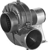 |
Blowers with a totally enclosed motor enclosure can be used in dirty, dusty, and wet environments.
Multidirection Mounting Bracket—Blowers with a multidirection mounting bracket can be rotated to discharge air in any direction.
Overall | Temp. | Mounting | |||||||||||||||
|---|---|---|---|---|---|---|---|---|---|---|---|---|---|---|---|---|---|
Airflow @ SP | Volume (Sound), dB | Motor Speed, rpm | Outlet Dia. | Inlet Dia. | Wheel Dia. | Ht. | Wd. | Dp. | Min. | Max., ° F | Fasteners Included | Hole Dia. | Includes | Each | |||
12V DC | |||||||||||||||||
Hardwire | |||||||||||||||||
| 105 ft³/min @ 0 in. H₂O | 60 | 3,500 | 3" | 3" | 3" | 5 1/2" | 5" | 6 3/4" | Not Rated | 130 | No | 1/4" | Multidirection Mounting Bracket | 2059K12 | 0000000 | ||
| 250 ft³/min @ 0 in. H₂O | 66 | 2,500 | 4" | 4" | 4" | 9 5/8" | 9 1/4" | 8 3/4" | Not Rated | 130 | No | 1/4" | Multidirection Mounting Bracket | 2059K14 | 000000 | ||
24V DC | |||||||||||||||||
Hardwire | |||||||||||||||||
| 150 ft³/min @ 0 in. H₂O | 68 | 2,500 | 2 3/4" | 3" | 3" | 7 7/8" | 6 3/4" | 7 7/8" | Not Rated | 130 | No | 1/4" | — | 2059K39 | 000000 | ||
| 250 ft³/min @ 0 in. H₂O | 70 | 2,500 | 4" | 4" | 4" | 9 5/8" | 9 1/4" | 8 3/4" | Not Rated | 130 | No | 1/4" | Multidirection Mounting Bracket | 2059K24 | 000000 | ||
With Rectangular Outlet and Round Inlet—Open Motor Enclosure
|
Outlet | Overall | Temp., ° F | Mounting | ||||||||||||||
|---|---|---|---|---|---|---|---|---|---|---|---|---|---|---|---|---|---|
Airflow @ SP | Volume (Sound) | Motor Speed, rpm | Ht. | Wd. | Inlet Dia. | Wheel Dia. | Ht. | Wd. | Dp. | Min. | Max. | Fasteners Included | Hole Dia. | Each | |||
12V DC | |||||||||||||||||
Hardwire | |||||||||||||||||
| 290 ft³/min @ 0 in. H₂O | Not Rated | 3,700 | 4 1/8" | 2 3/16" | 3 3/8" | 4 7/16" | 5 1/2" | 6 9/16" | 5 1/4" | -40 | 175 | No | 3/16" | 2059K38 | 000000 | ||
| 375 ft³/min @ 0 in. H₂O | Not Rated | 3,950 | 2 1/8" | 4 1/8" | 3" | 3 1/4" | 5" | 4 1/2" | 14" | -40 | 175 | No | 1/4" | 2059K36 | 00000 | ||
24V DC | |||||||||||||||||
Hardwire | |||||||||||||||||
| 385 ft³/min @ 0 in. H₂O | Not Rated | 3,750 | 2 1/8" | 4 1/8" | 3" | 3 1/4" | 5" | 4 1/2" | 14" | -40 | 175 | No | 1/4" | 2059K37 | 00000 | ||
Hazardous Location Spark-Resistant Blowers
With Round Outlet and Round Inlet
|
Overall | Mounting | |||||||||||||||||||
|---|---|---|---|---|---|---|---|---|---|---|---|---|---|---|---|---|---|---|---|---|
Airflow @ SP | Volume (Sound) @ Distance | Motor Speed, rpm | Power, hp | Outlet Dia. | Inlet Dia. | Wheel Dia. | Ht. | Wd. | Dp. | Current | Temp. Range, ° F | Housing Material | Hazardous Location Rating | Enclosure Rating | Fasteners Included | Hole Dia. | Each | |||
120V AC/230V AC | ||||||||||||||||||||
Single Phase—Hardwire | ||||||||||||||||||||
| 295 ft³/min @ 1 in. H₂O 505 ft³/min @ 1/4 in. H₂O | 55 dBA @ 15 ft. | 1,750 | 1/3 | 6" | 6" | 6 1/4" | 14 1/8" | 12 1/4" | 13 1/4" | 6.0 amp/3.0 amp | 0 to 150 | Aluminum | NEC Class I Divisions 1, 2 Group D NEC Class II Divisions 1, 2 Groups F, G | IP44 | No | 7/16" | 1955K63 | 000000000 | ||
| 320 ft³/min @ 1 in. H₂O 375 ft³/min @ 1/4 in. H₂O | 60 dBA @ 15 ft. | 3,450 | 1/3 | 4" | 5" | 4 3/4" | 12 5/8" | 9 7/8" | 12 1/4" | 7.0 amp/3.5 amp | 0 to 150 | Aluminum | NEC Class I Divisions 1, 2 Group D NEC Class II Divisions 1, 2 Groups F, G | IP44 | No | 7/16" | 1955K62 | 00000000 | ||
| 995 ft³/min @ 1 in. H₂O 1,070 ft³/min @ 1/4 in. H₂O | 70 dBA @ 15 ft. | 3,450 | 1 1/2 | 6" | 6" | 6 1/4" | 14 1/8" | 12 1/4" | 13 1/4" | 15.4 amp/8.4 amp | 0 to 150 | Aluminum | NEC Class I Divisions 1, 2 Groups C, D NEC Class II Divisions 1, 2 Groups F, G | IP54 | No | 7/16" | 1955K82 | 00000000 | ||
| 1,045 ft³/min @ 1/4 in. H₂O | 55 dBA @ 15 ft. | 1,150 | 1/3 | 8" | 8" | 8 1/4" | 18 3/4" | 14 3/4" | 15 3/8" | 6.8 amp/3.4 amp | 0 to 150 | Aluminum | NEC Class I Divisions 1, 2 Group D NEC Class II Divisions 1, 2 Groups F, G | IP44 | No | 7/16" | 1955K81 | 00000000 | ||
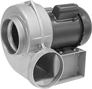
Wide-Flow Equipment-Cooling Blowers
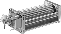 |
Also known as crossflow blowers, these create a wider stream of concentrated air than other equipment-cooling blowers to blow away the heat generated by electronic equipment, induction heaters, and high-wattage bulbs. Use them to keep heat-sensitive equipment such as electronic components cool. All have UL recognized components and are CSA certified.
Overall, mm | Outlet, mm | ||||||||||||
|---|---|---|---|---|---|---|---|---|---|---|---|---|---|
Ht. | Wd. | Dp. | Ht. | Wd. | Airflow, ft³/min | Temp. Range, ° F | Volume (Sound), dBA | Motor Speed, rpm | Current, amp | Each | |||
Rectangle | |||||||||||||
120V AC, Single Phase, 60 Hz—Wire Leads | |||||||||||||
| 108 | 279.4 | 88.9 | 22.23 | 190.5 | 120 | 30 to 140 | — | 2,600 | 0.9 | 2087K14 | 0000000 | ||
| 108 | 355.6 | 88.9 | 22.23 | 266.7 | 160 | 30 to 140 | — | 2,600 | 1.2 | 2087K17 | 000000 | ||
| 108 | 447.68 | 88.9 | 22.23 | 342.9 | 220 | 30 to 140 | — | 2,600 | 1.3 | 2087K22 | 000000 | ||
12V DC—Wire Leads | |||||||||||||
| 50.8 | 412.75 | 47.63 | 15.88 | 352.43 | 91 | -4 to 140 | 51 | 3,600 | 0.8 | 2087K15 | 000000 | ||
24V DC—Wire Leads | |||||||||||||
| 50.8 | 257.18 | 47.63 | 15.88 | 196.85 | 58 | -4 to 140 | 51 | 4,250 | 0.3 | 2087K13 | 000000 | ||
| 50.8 | 412.75 | 47.63 | 15.88 | 352.43 | 91 | -4 to 140 | 51 | 3,600 | 0.4 | 2087K16 | 000000 | ||
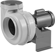
Blowers
With Rectangular Outlet and Round Inlet—Open Dripproof (ODP) Motor Enclosure
 |
Blowers | Replacement Wheels | |||||||||||||||||||||
|---|---|---|---|---|---|---|---|---|---|---|---|---|---|---|---|---|---|---|---|---|---|---|
Outlet | Overall | Mounting | ||||||||||||||||||||
Airflow @ SP | Volume (Sound) @ Distance | Motor Speed, rpm | Power, hp | Ht. | Wd. | Inlet Dia. | Wheel Dia. | Ht. | Wd. | Dp. | Wt., lb. | Current | Temp. Range, ° F | Housing Material | Fasteners Included | Hole Dia. | Each | Each | ||||
120V AC | ||||||||||||||||||||||
Single Phase—Hardwire | ||||||||||||||||||||||
| 305 ft³/min @ 3/4 in. H₂O 520 ft³/min @ 1/4 in. H₂O | 48 dB @ 15 ft. | 1,725 | 1/4 | 7 1/4" | 4 1/4" | 6" | 6" | 14" | 10 1/4" | 13 3/4" | 28 | 2.6 amp/1.3 amp | -4 to 180 | Steel | No | 3/8" | 1963K131 | 000000000 | 1963K511 | 0000000 | ||
120V AC/230V AC | ||||||||||||||||||||||
Single Phase—Hardwire | ||||||||||||||||||||||
| 860 ft³/min @ 3/4 in. H₂O 1,130 ft³/min @ 1/4 in. H₂O | 52 dB @ 15 ft. | 1,200 | 1/3 | 10 7/8" | 6 1/4" | 9" | 9" | 17 3/4" | 15 1/8" | 15 3/4" | 54 | 8.6 amp/4.3 amp | -4 to 180 | Steel | No | 3/8" | 1963K136 | 00000000 | 1963K544 | 000000 | ||
| 870 ft³/min @ 3/4 in. H₂O 1,055 ft³/min @ 1/4 in. H₂O | 53 dB @ 15 ft. | 1,725 | 1/3 | 8 3/8" | 5 1/2" | 8" | 7 1/2" | 15 5/8" | 13 1/2" | 15" | 44 | 6 amp/3 amp | -4 to 180 | Steel | No | 3/8" | 1963K132 | 00000000 | 1963K522 | 000000 | ||
| 1,505 ft³/min @ 3/4 in. H₂O 1,875 ft³/min @ 1/4 in. H₂O | 58 dB @ 15 ft. | 1,200 | 3/4 | 11 3/4" | 7 1/8" | 10" | 10" | 19 3/4" | 17 1/2" | 20 1/8" | 84 | 6.3 amp/3.5 amp | -4 to 180 | Steel | No | 3/8" | 1963K137 | 00000000 | 1963K533 | 000000 | ||
230V AC/460V AC | ||||||||||||||||||||||
Three Phase—Hardwire | ||||||||||||||||||||||
| 305 ft³/min @ 3/4 in. H₂O 520 ft³/min @ 1/4 in. H₂O | 48 dB @ 15 ft. | 1,725 | 1/4 | 7 1/4" | 4 1/4" | 6" | 6" | 14" | 10 1/4" | 13 3/4" | 34 | 1 amp/0.5 amp | -4 to 180 | Steel | No | 3/8" | 1963K133 | 00000000 | 1963K512 | 000000 | ||
| 860 ft³/min @ 3/4 in. H₂O 1,130 ft³/min @ 1/4 in. H₂O | 51 dB @ 15 ft. | 1,200 | 1/3 | 10 7/8" | 6 1/4" | 9" | 9" | 17 3/4" | 15 1/8" | 15 3/4" | 49 | 1.9 amp/0.9 amp | -4 to 180 | Steel | No | 3/8" | 1963K138 | 00000000 | 1963K545 | 000000 | ||
| 870 ft³/min @ 3/4 in. H₂O 1,055 ft³/min @ 1/4 in. H₂O | 52 dB @ 15 ft. | 1,725 | 1/3 | 8 3/8" | 5 1/2" | 8" | 7 1/2" | 15 5/8" | 13 1/2" | 15" | 37 | 1.4 amp/0.7 amp | -4 to 180 | Steel | No | 3/8" | 1963K134 | 00000000 | 1963K524 | 000000 | ||
| 1,505 ft³/min @ 3/4 in. H₂O 1,875 ft³/min @ 1/4 in. H₂O | 57 dB @ 15 ft. | 1,200 | 3/4 | 11 3/4" | 7 1/8" | 10" | 10" | 19 3/4" | 17 1/2" | 20 1/8" | 67 | 3.1 amp/1.55 amp | -4 to 180 | Steel | No | 3/8" | 1963K135 | 00000000 | 1963K534 | 000000 | ||
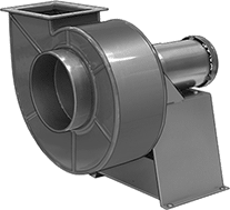
Chemical-Resistant Blowers
With Round Outlet and Round Inlet—Totally Enclosed Motor Enclosure
 | 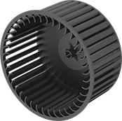 |
Replacement Wheels |
Blowers | Replacement Wheels | |||||||||||||||||||
|---|---|---|---|---|---|---|---|---|---|---|---|---|---|---|---|---|---|---|---|---|
Overall | Mounting | |||||||||||||||||||
Airflow @ SP | Volume (Sound) @ Distance | Motor Speed, rpm | Power, hp | Outlet Dia. | Inlet Dia. | Wheel Dia. | Ht. | Wd. | Dp. | Wt., lb. | Current | Housing Material | Fasteners Included | Hole Dia. | Each | Each | ||||
120V AC/230V AC | ||||||||||||||||||||
Single Phase—Hardwire | ||||||||||||||||||||
| 185 ft³/min @ 1/2 in. H₂O | Not Rated | 1,725 | 1/6 | 5" | 6" | 5 11/16" | 12 1/4" | 11" | 14 1/2" | 32 | 3.8 amp/1.9 amp | PVC | No | 3/8" | 2093K24 | 000000000 | 2093K211 | 0000000 | ||
| 810 ft³/min @ 1 in. H₂O 960 ft³/min @ 1/2 in. H₂O | Not Rated | 1,725 | 1/3 | 8" | 8" | 7" | 16 3/4" | 15 1/8" | 18 1/2" | 53 | 6.0 amp/3.0 amp | Fiberglass | No | 3/8" | 2093K11 | 00000000 | 2093K31 | 000000 | ||
With Rectangular Outlet and Round Inlet—Totally Enclosed Motor Enclosure
 | |
Replacement Wheels |
PVC Housing—PVC housing offers greater chemical resistance than the fiberglass housing. It resists strong oxidizing acids such as sulfuric acid but will not withstand contact with perchloric acid.
Cannot Be Sold to California—Blowers that cannot be sold to the listed areas are restricted due to energy efficiency requirements.
Blowers | Replacement Wheels | |||||||||||||||||||||
|---|---|---|---|---|---|---|---|---|---|---|---|---|---|---|---|---|---|---|---|---|---|---|
Outlet | Overall | Mounting | ||||||||||||||||||||
Airflow @ SP | Volume (Sound) @ Distance | Motor Speed, rpm | Power, hp | Ht. | Wd. | Inlet Dia. | Wheel Dia. | Ht. | Wd. | Dp. | Wt., lb. | Current | Housing Material | Fasteners Included | Hole Dia. | Cannot Be Sold To | Each | Each | ||||
208V AC to 230V AC/460V AC | ||||||||||||||||||||||
Three Phase—Hardwire | ||||||||||||||||||||||
| 2,300 ft³/min @ 1/2 in. H₂O 2,300 ft³/min @ 1 in. H₂O | Not Rated | 1,725 | 1 1/2 | 9 3/8" | 6 11/16" | 10" | 12" | 24 1/4" | 23" | 24 1/4" | 124 | 4.5 amp/2.2 amp | PVC | No | 3/8" | California | 2093K75 | 000000000 | 2093K36 | 000000000 | ||
| 4,700 ft³/min @ 1 in. H₂O 4,900 ft³/min @ 1/2 in. H₂O | Not Rated | 1,725 | 5 | 11 7/8" | 9 3/4" | 13" | 14 1/2" | 31 1/2" | 30" | 29 3/4" | 172 | 13.9 amp/6.7 amp | PVC | No | 3/8" | California | 2093K85 | 00000000 | 2093K38 | 00000000 | ||
Hazardous Location Chemical-Resistant Blowers
With Round Outlet and Round Inlet
| |
Replacement Wheels |
Blowers | Replacement Wheels | |||||||||||||||||||
|---|---|---|---|---|---|---|---|---|---|---|---|---|---|---|---|---|---|---|---|---|
Overall | Mounting | |||||||||||||||||||
Airflow @ SP | Volume (Sound) @ Distance | Motor Speed, rpm | Power, hp | Outlet Dia. | Inlet Dia. | Wheel Dia. | Ht. | Wd. | Dp. | Current | Housing Material | Hazardous Location Rating | Fasteners Included | Hole Dia. | Each | Each | ||||
120V AC | ||||||||||||||||||||
Single Phase—Hardwire | ||||||||||||||||||||
| 185 ft³/min @ 1/2 in. H₂O | Not Rated | 1,725 | 1/6 | 5" | 6" | 5 11/16" | 12 1/4" | 11" | 15 1/2" | 1.9 amp | PVC | NEC Class I Divisions 1, 2 Group D NEC Class II Divisions 1, 2 Groups F, G | No | 3/8" | 2093K17 | 000000000 | 2093K211 | 0000000 | ||
120V AC/230V AC | ||||||||||||||||||||
Single Phase—Hardwire | ||||||||||||||||||||
| 810 ft³/min @ 1 in. H₂O 960 ft³/min @ 1/2 in. H₂O | Not Rated | 1,725 | 1/3 | 8" | 8" | 7" | 16 3/4" | 15 1/8" | 21 1/2" | 6.0 amp/3.0 amp | Fiberglass | NEC Class I Divisions 1, 2 Group D NEC Class II Divisions 1, 2 Groups F, G | No | 3/8" | 2093K12 | 00000000 | 2093K31 | 000000 | ||
With Rectangular Outlet and Round Inlet
| |
Replacement Wheels |
PVC Housing—PVC housing offers greater chemical resistance than the fiberglass housing. It resists strong oxidizing acids such as sulfuric acid but will not withstand contact with perchloric acid.
Cannot Be Sold to California—Blowers that cannot be sold to the listed areas are restricted due to energy efficiency requirements.
Blowers | Replacement Wheels | |||||||||||||||||||||
|---|---|---|---|---|---|---|---|---|---|---|---|---|---|---|---|---|---|---|---|---|---|---|
Outlet | Overall | Mounting | ||||||||||||||||||||
Airflow @ SP | Volume (Sound) @ Distance | Motor Speed, rpm | Power, hp | Ht. | Wd. | Inlet Dia. | Wheel Dia. | Ht. | Wd. | Dp. | Current | Housing Material | Hazardous Location Rating | Fasteners Included | Hole Dia. | Cannot Be Sold To | Each | Each | ||||
230V AC/460V AC | ||||||||||||||||||||||
Three Phase—Hardwire | ||||||||||||||||||||||
| 2,300 ft³/min @ 1/2 in. H₂O 2,300 ft³/min @ 1 in. H₂O | Not Rated | 1,725 | 1 1/2 | 9 3/8" | 6 11/16" | 10" | 12" | 24 1/4" | 23" | 24 1/4" | 4.4 amp/2.2 amp | PVC | NEC Class I Divisions 1, 2 Group D NEC Class II Divisions 1, 2 Groups F, G | No | 3/8" | California | 2093K76 | 000000000 | 2093K36 | 000000000 | ||
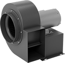
Equipment-Cooling Blowers
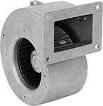 |
Create a more concentrated stream of air than equipment-cooling fans to blow away the heat generated by electronic equipment, induction heaters, and high-wattage bulbs. Use these fans to keep heat-sensitive equipment such as electronic components cool.
