Filter by
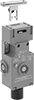
Switch Starting Position
Wire Connection
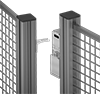
Housing Material
Switch Designation
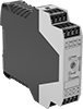
Electrical Connection
Certification
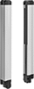
Light Beam Height
DFARS Specialty Metals
U.S.–Mexico–Canada Agreement (USMCA) Qualifying
Export Control Classification Number (ECCN)
Safety Switches
Other Products