


Filter by
Product Family
Actuator Style
Environment
Operation Type
Switch Starting Position
Wire Connection
Switch Designation
Electrical Connection
Switch Type
DFARS Specialty Metals
Export Control Classification Number (ECCN)
REACH
RoHS
Certification
Manual-Reset Safety Limit Switches
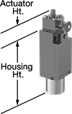 | 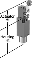 | 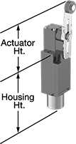 |
Style A | Style B | Style C |
Prevent equipment from automatically restarting—these switches must be manually reset each time they're actuated. Pull the knob to reset. Positive-force contacts open the circuit when actuated, even if a spring fails or the contacts stick. These switches send a signal to your circuit when an object hits the actuator—for instance, a box on a conveyor runs into the switch, stopping the conveyor. They open and close circuits as fast as snap-acting switches, but they have a bigger actuator for large objects.
Rated IP67, these switches seal out water if they’re washed down or briefly submersed.
Style B—Style B have a roller lever actuator that allows parts to glide across the actuation surface with minimal friction.
Style C—Style C have a roller lever actuator that allows parts to glide across the actuation surface with minimal friction. You can also adjust the actuator's height, making it easier to align the switch with the target during installation.
Housing | |||||||||||||||||||
|---|---|---|---|---|---|---|---|---|---|---|---|---|---|---|---|---|---|---|---|
Style | No. of Circuits Controlled | Switch Starting Position | Switch Action | Switch Designation | Switching Current @ Voltage | Max. Voltage | Operating Temp. Range, ° F | Actuator Ht. | No. of Terminals | Lg. | Ht. | Dp. | Housing Material | Conduit Thread Size | Enclosure Rating | Each | |||
Plunger Actuator | |||||||||||||||||||
Screw-Terminal Wire Connection | |||||||||||||||||||
| A | 2 | 1 Off and 1 On | Maintained | DPST-1NO/1NC | 10 amp @ 240V AC, 2.5 amp @ 125V DC | 300V AC 250V DC | -22 to 158 | 1" | 4 | 1.2" | 3.4" | 1.2" | Plastic | M20 | IP67 | 7336K51 | 000000 | ||
Roller Lever Actuator | |||||||||||||||||||
Screw-Terminal Wire Connection | |||||||||||||||||||
| B | 2 | 1 Off and 1 On | Maintained | DPST-1NO/1NC | 10 amp @ 240V AC, 2.5 amp @ 125V DC | 300V AC 250V DC | -22 to 158 | 2.4" | 4 | 1.2" | 3.4" | 1.2" | Plastic | M20 | IP67 | 7336K53 | 00000 | ||
| C | 2 | 1 Off and 1 On | Maintained | DPST-1NO/1NC | 10 amp @ 240V AC, 2.5 amp @ 125V DC | 300V AC 250V DC | -22 to 158 | 2.1" to 3.9" | 4 | 1.2" | 3.4" | 1.2" | Plastic | M20 | IP67 | 7336K54 | 000000 | ||
Tilt Switches
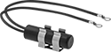 | 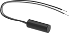 |  |
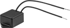
Style A | Style B | Style C |
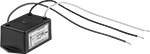 |  | |
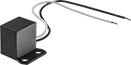
Style D | Style E |
Style | No. of Circuits Controlled | Switch Starting Position | Switch Designation | Switching Current @ Voltage | Max. Voltage | Differential Angle | No. of Wire Leads | Dia. | Lg. | Ht. | Dp. | Housing Material | Enclosure Rating | Each | |||
|---|---|---|---|---|---|---|---|---|---|---|---|---|---|---|---|---|---|
Ring-Terminal Wire Connection | |||||||||||||||||
| A | 1 | 1 Off | SPST-NO | 0.1 amp @ 120V AC, 0.25 amp @ 24V DC | 60V DC/120V AC | 15° | 2 | 0.53" | 1.88" | — | — | Plastic | NEMA 4, IP67 | 3108K1 | 000000 | ||
Spade-Terminal Wire Connection | |||||||||||||||||
| A | 1 | 1 Off | SPST-NO | 2.5 amp @ 120V AC | 280V AC | 15° | 2 | 0.53" | 1.88" | — | — | Plastic | NEMA 4, IP67 | 3108K2 | 00000 | ||
Wire Lead Connection | |||||||||||||||||
| B | 1 | 1 Off | SPST-NO | 20 amp @ 24V DC | 40V DC | 10° | 2 | 0.75" | 2" | — | — | Plastic | NEMA 4, IP67 | 3108K4 | 00000 | ||
| C | 1 | 1 Off | SPST-NO | 10 amp @ 12V DC | 18V DC | 30° | 2 | — | 1.22" | 1.07" | 0.8" | Plastic | NEMA 4, IP67 | 3108K3 | 00000 | ||
| D | 1 | 1 Off | SPST-NO | 15 amp @ 120V AC | 120V AC | 15° | 3 | — | 3" | 1.5" | 2" | Plastic | NEMA 4, IP67 | 3108K5 | 000000 | ||
| D | 1 | 1 Off | SPST-NO | 15 amp @ 220V AC | 220V AC | 15° | 3 | — | 3" | 1.5" | 2" | Plastic | NEMA 4, IP67 | 3108K6 | 000000 | ||
| E | 1 | 1 On | SPST-NC | 2 amp @ 120V AC | 220V AC | 25° | 2 | — | 1.5" | 0.8" | 1.3" | Plastic | NEMA 4, IP67 | 3108K8 | 00000 | ||
| E | 1 | 1 On | SPST-NC | 2 amp @ 120V AC | 220V AC | 40° | 2 | — | 1.5" | 0.8" | 1.3" | Plastic | NEMA 4, IP67 | 3108K7 | 00000 | ||
