


Filter by


Height

Working Orientation
Weight Capacity @ Maximum Lift
Overall Height
Application
Weight Capacity @ Minimum Height
Weight Capacity @ Height
Export Control Classification Number (ECCN)
DFARS Specialty Metals
Scissor Jacks
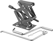 |
Fit this compact jack under low-height loads.
Warning: Never use to support people or loads over people.
Weight Capacity @ Min. Ht. | Weight Capacity @ 7" Ht. | Weight Capacity @ Max. Lift | Saddle | Base | Mounting | ||||||||||||||||||||||||||||||||||||||||||||||||||||||||||||||||||||||||||||||||||||||||||||||
|---|---|---|---|---|---|---|---|---|---|---|---|---|---|---|---|---|---|---|---|---|---|---|---|---|---|---|---|---|---|---|---|---|---|---|---|---|---|---|---|---|---|---|---|---|---|---|---|---|---|---|---|---|---|---|---|---|---|---|---|---|---|---|---|---|---|---|---|---|---|---|---|---|---|---|---|---|---|---|---|---|---|---|---|---|---|---|---|---|---|---|---|---|---|---|---|---|---|---|---|
tons | lbs. | tons | lbs. | tons | lbs. | Ht. | Max. Lift | Max. Wd. | Type | Lg. | Wd. | Lg. | Wd. | Handle Lg. | Body Material | Fasteners Included | No. of Holes | Hole Dia. | Features | Each | |||||||||||||||||||||||||||||||||||||||||||||||||||||||||||||||||||||||||||||||
Rigid Saddle | |||||||||||||||||||||||||||||||||||||||||||||||||||||||||||||||||||||||||||||||||||||||||||||||||||
| 1/8 ton @ 4" | 250 lb. @ 4" | 1/4 ton @ 7" | 675 lb. @ 7" | 1 1/2 ton @ 9" | 3,000 lb. @ 9" | 4" to 13" | 9" | 10 1/2" | Flat | 5 1/8" | 2" | 7 3/8" | 4 1/4" | 22" | Steel | No | 2 | 3/8" | Two-Piece Removable Handle | 2952T51 | 000000 | ||||||||||||||||||||||||||||||||||||||||||||||||||||||||||||||||||||||||||||||
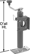
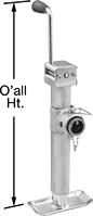
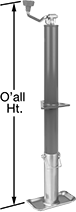
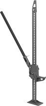
Leveling Jacks
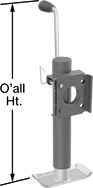 |  |  | 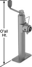 |
Side Handle Style A | Top Handle Style A | Side Handle Style B | Top Handle Style B |
 | 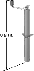 | 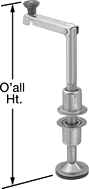 | |
Top Handle Style C | Top Handle Style D | Top Handle Style E |
Mounting | |||||||||||||||||||||||||||||||||||||||||||||||||||||||||||||||||||||||||||||||||||||||||||||||||||
|---|---|---|---|---|---|---|---|---|---|---|---|---|---|---|---|---|---|---|---|---|---|---|---|---|---|---|---|---|---|---|---|---|---|---|---|---|---|---|---|---|---|---|---|---|---|---|---|---|---|---|---|---|---|---|---|---|---|---|---|---|---|---|---|---|---|---|---|---|---|---|---|---|---|---|---|---|---|---|---|---|---|---|---|---|---|---|---|---|---|---|---|---|---|---|---|---|---|---|---|
Style | Weight Capacity | Ht. | Max. Lift | Overall Ht. | Handle Lg. | Body Material | For Hole Dia. | Fasteners Included | No. of Holes | Hole Dia. | Hole Lg. | Hole Wd. | Features | Each | |||||||||||||||||||||||||||||||||||||||||||||||||||||||||||||||||||||||||||||||||||||
Weld On Side Mount with Rectangular Mounting Plate | |||||||||||||||||||||||||||||||||||||||||||||||||||||||||||||||||||||||||||||||||||||||||||||||||||
Side Handle | |||||||||||||||||||||||||||||||||||||||||||||||||||||||||||||||||||||||||||||||||||||||||||||||||||
| A | 1 ton/2,000 lb. | 10 7/8" to 20 7/8" | 10" | 22 3/4" | 5 7/8" | Steel | — | — | — | — | — | — | Foot Plate | 2963T44 | 0000000 | ||||||||||||||||||||||||||||||||||||||||||||||||||||||||||||||||||||||||||||||||||||
| A | 2 1/2 ton/5,000 lb. | 10 3/8" to 20 3/8" | 10" | 22 7/8" | 6 1/2" | Steel | — | — | — | — | — | — | Foot Plate | 2963T48 | 00000 | ||||||||||||||||||||||||||||||||||||||||||||||||||||||||||||||||||||||||||||||||||||
| A | 2 1/2 ton/5,000 lb. | 15 3/8" to 30 3/8" | 15" | 27 7/8" | 6 1/2" | Steel | — | — | — | — | — | — | Foot Plate | 2963T49 | 000000 | ||||||||||||||||||||||||||||||||||||||||||||||||||||||||||||||||||||||||||||||||||||
Top Handle | |||||||||||||||||||||||||||||||||||||||||||||||||||||||||||||||||||||||||||||||||||||||||||||||||||
| A | 2 1/2 ton/5,000 lb. | 14 1/2" to 29 1/2" | 15" | 27 1/2" | 7 5/8" | Steel | — | — | — | — | — | — | Foot Plate | 2963T35 | 000000 | ||||||||||||||||||||||||||||||||||||||||||||||||||||||||||||||||||||||||||||||||||||
Weld On Side Mount with Square Mounting Plate | |||||||||||||||||||||||||||||||||||||||||||||||||||||||||||||||||||||||||||||||||||||||||||||||||||
Side Handle | |||||||||||||||||||||||||||||||||||||||||||||||||||||||||||||||||||||||||||||||||||||||||||||||||||
| A | 1 ton/2,000 lb. | 15" to 30 1/2" | 15 1/2" | 32 3/4" | 6 1/8" | Steel | — | — | — | — | — | — | Foot Plate | 2963T52 | 000000 | ||||||||||||||||||||||||||||||||||||||||||||||||||||||||||||||||||||||||||||||||||||
Top Handle | |||||||||||||||||||||||||||||||||||||||||||||||||||||||||||||||||||||||||||||||||||||||||||||||||||
| A | 1 ton/2,000 lb. | 14 3/4" to 29 3/4" | 15" | 30" | 6" | Steel | — | — | — | — | — | — | Foot Plate | 2963T51 | 00000 | ||||||||||||||||||||||||||||||||||||||||||||||||||||||||||||||||||||||||||||||||||||
Weld On Side Mount with Tubular Mounting Plate | |||||||||||||||||||||||||||||||||||||||||||||||||||||||||||||||||||||||||||||||||||||||||||||||||||
Side Handle | |||||||||||||||||||||||||||||||||||||||||||||||||||||||||||||||||||||||||||||||||||||||||||||||||||
| B | 1 ton/2,000 lb. | 10 7/8" to 20 7/8" | 10" | 23" | 5 7/8" | Steel | — | — | — | — | — | — | Foot Plate | 2963T71 | 000000 | ||||||||||||||||||||||||||||||||||||||||||||||||||||||||||||||||||||||||||||||||||||
| B | 1 ton/2,000 lb. | 15" to 30 1/2" | 15 1/2" | 32 3/4" | 6 1/8" | Steel | — | — | — | — | — | — | Foot Plate | 2963T53 | 000000 | ||||||||||||||||||||||||||||||||||||||||||||||||||||||||||||||||||||||||||||||||||||
| B | 2 1/2 ton/5,000 lb. | 10 1/2" to 20 1/2" | 10" | 23" | 6 1/2" | Steel | — | — | — | — | — | — | Foot Plate | 2963T73 | 000000 | ||||||||||||||||||||||||||||||||||||||||||||||||||||||||||||||||||||||||||||||||||||
| B | 2 1/2 ton/5,000 lb. | 15 1/2" to 30 1/2" | 15" | 28" | 6 1/2" | Steel | — | — | — | — | — | — | Foot Plate | 2963T74 | 000000 | ||||||||||||||||||||||||||||||||||||||||||||||||||||||||||||||||||||||||||||||||||||
| B | 3 1/2 ton/7,000 lb. | 11" to 21" | 10" | 25 5/8" | 8 1/2" | Steel | — | — | — | — | — | — | Foot Plate | 2963T75 | 000000 | ||||||||||||||||||||||||||||||||||||||||||||||||||||||||||||||||||||||||||||||||||||
| B | 5 ton/10,000 lb. | 17" to 29 5/8" | 12 5/8" | 39 1/2" | 13 1/2" | Steel | — | — | — | — | — | — | Foot Plate | 2963T81 | 000000 | ||||||||||||||||||||||||||||||||||||||||||||||||||||||||||||||||||||||||||||||||||||
Top Handle | |||||||||||||||||||||||||||||||||||||||||||||||||||||||||||||||||||||||||||||||||||||||||||||||||||
| B | 2 1/2 ton/5,000 lb. | 11 1/4" to 21 1/4" | 10" | 18" | 7 5/8" | Steel | — | — | — | — | — | — | Foot Plate | 2963T18 | 000000 | ||||||||||||||||||||||||||||||||||||||||||||||||||||||||||||||||||||||||||||||||||||
Bolt On/Through Hole with Triangular Mounting Plate | |||||||||||||||||||||||||||||||||||||||||||||||||||||||||||||||||||||||||||||||||||||||||||||||||||
Top Handle | |||||||||||||||||||||||||||||||||||||||||||||||||||||||||||||||||||||||||||||||||||||||||||||||||||
| C | 2 1/2 ton/5,000 lb. | 10 1/8" to 25 1/8" | 15" | 24 1/8" | 7 5/8" | Steel | 2 1/4" | No | 3 | — | 7/16" | 13/16" | Foot Plate | 2933T61 | 00000 | ||||||||||||||||||||||||||||||||||||||||||||||||||||||||||||||||||||||||||||||||||||
Bolt On/Weld On/Through Hole with Triangular Mounting Plate | |||||||||||||||||||||||||||||||||||||||||||||||||||||||||||||||||||||||||||||||||||||||||||||||||||
Top Handle | |||||||||||||||||||||||||||||||||||||||||||||||||||||||||||||||||||||||||||||||||||||||||||||||||||
| D | 2 1/2 ton/5,000 lb. | 10 7/8" to 25 7/8" | 15" | 24 3/8" | 7 5/8" | Steel | 2 1/4" | No | 3 | — | 7/16" | 13/16" | — | 2933T35 | 000000 | ||||||||||||||||||||||||||||||||||||||||||||||||||||||||||||||||||||||||||||||||||||
Bolt On/Through Hole with Round Mounting Plate | |||||||||||||||||||||||||||||||||||||||||||||||||||||||||||||||||||||||||||||||||||||||||||||||||||
Top Handle | |||||||||||||||||||||||||||||||||||||||||||||||||||||||||||||||||||||||||||||||||||||||||||||||||||
| E | 2 1/2 ton/5,000 lb. | 4 1/2" to 13 1/2" | 9" | 19 3/4" | 8 3/4" | Steel | 1 1/4" | No | 6 | 1/4" | — | — | Foot Plate, Slip-Resistant Rubber Pad | 2953T1 | 000000 | ||||||||||||||||||||||||||||||||||||||||||||||||||||||||||||||||||||||||||||||||||||
| E | 2 1/2 ton/5,000 lb. | 4 1/2" to 21 1/2" | 17" | 27 3/4" | 8 7/8" | Steel | 1 1/4" | No | 6 | 1/4" | — | — | Foot Plate, Slip-Resistant Rubber Pad | 2953T2 | 00000 | ||||||||||||||||||||||||||||||||||||||||||||||||||||||||||||||||||||||||||||||||||||
| E | 2 1/2 ton/5,000 lb. | 4 1/2" to 25 1/2" | 21" | 31 3/4" | 8 3/4" | Steel | 1 1/4" | No | 6 | 1/4" | — | — | Foot Plate, Slip-Resistant Rubber Pad | 2953T3 | 000000 | ||||||||||||||||||||||||||||||||||||||||||||||||||||||||||||||||||||||||||||||||||||
Two-Height Ratchet Jacks
 |
Choose between two lifting points—use the toe for lifting loads low to the ground, or use the saddle when you need a higher, more stable lifting point. The saddle is curved to cradle curved loads. Jacks have a ratcheting action that raises or lowers the load one notch at a time. A removable handle can be used at two different positions to get the best angle for lifting.
Warning: Never use to support people or loads over people.
Aluminum Body—Aluminum jacks are lighter than iron for easier portability.
Toe | Saddle | Base | |||||||||||||||||||||||||||||||||||||||||||||||||||||||||||||||||||||||||||||||||||||||||||||||||
|---|---|---|---|---|---|---|---|---|---|---|---|---|---|---|---|---|---|---|---|---|---|---|---|---|---|---|---|---|---|---|---|---|---|---|---|---|---|---|---|---|---|---|---|---|---|---|---|---|---|---|---|---|---|---|---|---|---|---|---|---|---|---|---|---|---|---|---|---|---|---|---|---|---|---|---|---|---|---|---|---|---|---|---|---|---|---|---|---|---|---|---|---|---|---|---|---|---|---|---|
Weight Capacity | Max. Lift | Ht. | Lg. | Wd. | Ht. | Movement | Lg. | Wd. | Lg. | Wd. | Handle Lg. | Handle Material | Each | ||||||||||||||||||||||||||||||||||||||||||||||||||||||||||||||||||||||||||||||||||||||
Iron Body | |||||||||||||||||||||||||||||||||||||||||||||||||||||||||||||||||||||||||||||||||||||||||||||||||||
| 5 ton/10,000 lb. | 7" | 1 3/4" to 8 3/4" | 2 1/2" | 1 1/8" | 14" to 21" | Rigid | 2 5/8" | 2 3/8" | 5" | 7 3/8" | 36" | Steel | 2954T1 | 0000000 | |||||||||||||||||||||||||||||||||||||||||||||||||||||||||||||||||||||||||||||||||||||
| 5 ton/10,000 lb. | 10" | 1 3/4" to 11 3/4" | 2 1/2" | 1 1/8" | 17" to 27" | Rigid | 2 5/8" | 2 3/8" | 5" | 7 3/8" | 36" | Steel | 2954T2 | 00000000 | |||||||||||||||||||||||||||||||||||||||||||||||||||||||||||||||||||||||||||||||||||||
| 5 ton/10,000 lb. | 13" | 1 3/4" to 14 3/4" | 2 1/2" | 1 1/8" | 20" to 33" | Rigid | 2 5/8" | 2 3/8" | 5" | 7 3/8" | 36" | Steel | 2954T3 | 00000000 | |||||||||||||||||||||||||||||||||||||||||||||||||||||||||||||||||||||||||||||||||||||
| 10 ton/20,000 lb. | 9 1/2" | 1 5/8" to 11 1/8" | 2 3/8" | 1 1/8" | 17 1/4" to 26 3/4" | Rigid | 2 7/8" | 2 5/8" | 6" | 8 3/4" | 60" | Steel | 2954T51 | 00000000 | |||||||||||||||||||||||||||||||||||||||||||||||||||||||||||||||||||||||||||||||||||||
| 10 ton/20,000 lb. | 12" | 2" to 14" | 2 3/8" | 2 1/2" | 21 5/8" to 33 5/8" | Rigid | 3" | 2 1/2" | 6 1/2" | 10 1/4" | 60" | Steel | 2954T4 | 00000000 | |||||||||||||||||||||||||||||||||||||||||||||||||||||||||||||||||||||||||||||||||||||
| 15 ton/30,000 lb. | 12 3/4" | 2 1/4" to 15" | 2 5/8" | 2 1/4" | 23 1/4" to 36" | Rigid | 3 1/2" | 2 7/8" | 8" | 10 1/4" | 70" | Steel | 2954T56 | 00000000 | |||||||||||||||||||||||||||||||||||||||||||||||||||||||||||||||||||||||||||||||||||||
| 15 ton/30,000 lb. | 18" | 2 1/4" to 20 1/4" | 2 5/8" | 2 1/4" | 28" to 46" | Rigid | 3 1/2" | 2 7/8" | 8" | 11" | 70" | Steel | 2954T57 | 00000000 | |||||||||||||||||||||||||||||||||||||||||||||||||||||||||||||||||||||||||||||||||||||
Aluminum Body | |||||||||||||||||||||||||||||||||||||||||||||||||||||||||||||||||||||||||||||||||||||||||||||||||||
| 10 ton/20,000 lb. | 12" | 2" to 14" | 2 3/8" | 2 1/2" | 21 5/8" to 33 5/8" | Rigid | 3" | 2 1/2" | 6 1/2" | 10 1/4" | 60" | Steel | 2954T9 | 00000000 | |||||||||||||||||||||||||||||||||||||||||||||||||||||||||||||||||||||||||||||||||||||
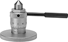
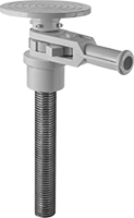
Wrench-Adjustable Screw Jacks
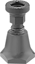 | 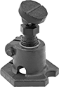 |
Rigid Saddle | Swivel Saddle |
Use these low-profile jacks in confined spaces. The screw adjustment lets you make small changes to the height of your load.
Warning: Never use to support people or loads over people.
Swivel Saddle—Jacks with swivel saddle keep loads from slipping. Also known as planer jacks, they have a side locking screw that keeps the jack extended and prevents lowering due to vibration.
Rigid Saddle—Jacks with rigid saddle are also known as spreader jacks.
Saddle | |||||||||||||||||||||||||||||||||||||||||||||||||||||||||||||||||||||||||||||||||||||||||||||||||||
|---|---|---|---|---|---|---|---|---|---|---|---|---|---|---|---|---|---|---|---|---|---|---|---|---|---|---|---|---|---|---|---|---|---|---|---|---|---|---|---|---|---|---|---|---|---|---|---|---|---|---|---|---|---|---|---|---|---|---|---|---|---|---|---|---|---|---|---|---|---|---|---|---|---|---|---|---|---|---|---|---|---|---|---|---|---|---|---|---|---|---|---|---|---|---|---|---|---|---|---|
Weight Capacity | Ht. | Max. Lift | Type | Dia. | Swivel Angle | Base Wd. | Body Material | Each | |||||||||||||||||||||||||||||||||||||||||||||||||||||||||||||||||||||||||||||||||||||||||||
Rigid Saddle | |||||||||||||||||||||||||||||||||||||||||||||||||||||||||||||||||||||||||||||||||||||||||||||||||||
| 3 ton/6,000 lb. | 3" to 4" | 1" | Flat | 1 1/2" | — | 2" | Steel | 2915T21 | 0000000 | ||||||||||||||||||||||||||||||||||||||||||||||||||||||||||||||||||||||||||||||||||||||||||
Swivel Saddle | |||||||||||||||||||||||||||||||||||||||||||||||||||||||||||||||||||||||||||||||||||||||||||||||||||
| 2 ton/4,000 lb. | 2 3/4" to 3 3/4" | 1" | Flat | 1 1/4" | 25° | 2 3/8" | Iron | 8791T6 | 000000 | ||||||||||||||||||||||||||||||||||||||||||||||||||||||||||||||||||||||||||||||||||||||||||
| 4 ton/8,000 lb. | 3 3/4" to 5 1/4" | 1 1/2" | Flat | 1 3/4" | 25° | 3 1/8" | Iron | 8791T5 | 000000 | ||||||||||||||||||||||||||||||||||||||||||||||||||||||||||||||||||||||||||||||||||||||||||
| 6 ton/12,000 lb. | 5 1/4" to 7 1/2" | 2 1/4" | Flat | 2 1/8" | 25° | 4" | Iron | 8791T7 | 000000 | ||||||||||||||||||||||||||||||||||||||||||||||||||||||||||||||||||||||||||||||||||||||||||
| 8 ton/16,000 lb. | 7 1/2" to 11 1/2" | 4" | Flat | 2 1/2" | 25° | 5 3/8" | Iron | 8791T8 | 000000 | ||||||||||||||||||||||||||||||||||||||||||||||||||||||||||||||||||||||||||||||||||||||||||
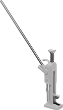
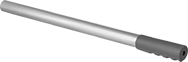
Bar-Adjustable Screw Jacks
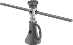 |
Shown with Turning Bar |
The turning bar (sold separately) gives you leverage to lift heavier loads than wrench-adjustable screw jacks. The screw adjustment lets you make small changes to the height of your load. The saddle swivels to keep loads from slipping. The jack head has multiple openings so you can choose the best angle for inserting the turning bar.
Warning: Never use to support people or loads over people.
Saddle | |||||||||||||||||||||||||||||||||||||||||||||||||||||||||||||||||||||||||||||||||||||||||||||||||||
|---|---|---|---|---|---|---|---|---|---|---|---|---|---|---|---|---|---|---|---|---|---|---|---|---|---|---|---|---|---|---|---|---|---|---|---|---|---|---|---|---|---|---|---|---|---|---|---|---|---|---|---|---|---|---|---|---|---|---|---|---|---|---|---|---|---|---|---|---|---|---|---|---|---|---|---|---|---|---|---|---|---|---|---|---|---|---|---|---|---|---|---|---|---|---|---|---|---|---|---|
Weight Capacity | Ht. | Max. Lift | Type | Dia. | Swivel Angle | Base Dia. | Body Material | Each | |||||||||||||||||||||||||||||||||||||||||||||||||||||||||||||||||||||||||||||||||||||||||||
Swivel Saddle | |||||||||||||||||||||||||||||||||||||||||||||||||||||||||||||||||||||||||||||||||||||||||||||||||||
| 12 ton/24,000 lb. | 9 5/8" to 13 3/8" | 3 3/4" | Flat | 2 7/8" | 9° | 4 3/4" | Iron | 2926T13 | 0000000 | ||||||||||||||||||||||||||||||||||||||||||||||||||||||||||||||||||||||||||||||||||||||||||
| 12 ton/24,000 lb. | 11 5/8" to 17 3/8" | 5 3/4" | Flat | 2 7/8" | 9° | 5 1/2" | Iron | 2926T14 | 000000 | ||||||||||||||||||||||||||||||||||||||||||||||||||||||||||||||||||||||||||||||||||||||||||
| 12 ton/24,000 lb. | 15 3/4" to 25 1/2" | 9 3/4" | Flat | 2 7/8" | 9° | 6 1/4" | Iron | 2926T16 | 000000 | ||||||||||||||||||||||||||||||||||||||||||||||||||||||||||||||||||||||||||||||||||||||||||
| 20 ton/40,000 lb. | 11 7/8" to 16 7/8" | 5" | Flat | 3 1/8" | 9° | 6" | Iron | 2926T18 | 000000 | ||||||||||||||||||||||||||||||||||||||||||||||||||||||||||||||||||||||||||||||||||||||||||
| 20 ton/40,000 lb. | 13 3/4" to 20 3/4" | 7" | Flat | 3 1/8" | 9° | 6 1/2" | Iron | 2926T19 | 000000 | ||||||||||||||||||||||||||||||||||||||||||||||||||||||||||||||||||||||||||||||||||||||||||
| 20 ton/40,000 lb. | 15 3/4" to 24 3/4" | 9" | Flat | 3 1/8" | 9° | 6 3/4" | Iron | 2926T21 | 000000 | ||||||||||||||||||||||||||||||||||||||||||||||||||||||||||||||||||||||||||||||||||||||||||
| 24 ton/48,000 lb. | 17" to 25 1/4" | 8 1/4" | Flat | 3 1/4" | 9° | 7 1/4" | Iron | 2926T24 | 000000 | ||||||||||||||||||||||||||||||||||||||||||||||||||||||||||||||||||||||||||||||||||||||||||
| 24 ton/48,000 lb. | 23" to 37 1/4" | 14 1/4" | Flat | 3 1/4" | 9° | 8 1/2" | Iron | 2926T27 | 000000 | ||||||||||||||||||||||||||||||||||||||||||||||||||||||||||||||||||||||||||||||||||||||||||
Ratchet Jacks
 |
These jacks can be used to lift, spread, push, pull, and clamp. The ratcheting action raises or lowers the load one notch at a time. For clamping, turn the top plate 90° and ratchet the jack to secure your workpiece.
Note: Jacks must be loaded with at least 150 lbs. to safely lower your load one notch at a time. When loaded with less than 150 lbs., the notches are bypassed and the load will drop freely.
Warning: Never use to support people or loads over people.
Toe | Base | Mounting | |||||||||||||||
|---|---|---|---|---|---|---|---|---|---|---|---|---|---|---|---|---|---|
Weight Capacity | Max. Clamping Force, lbf | Ht. | Max. Lift | Lg. | Wd. | Lg. | Wd. | Handle Lg. | Handle Material | Body Material | Fasteners Included | No. of Holes | Hole Dia. | Each | |||
| 1 1/4 ton/150 lb. to 2,500 lb. | 750 | 4 1/2" to 49 3/4" | 45 1/4" | 4 1/2" | 1 3/8" | 7" | 4" | 32" | Steel | Iron | No | 12 | 1/2" | 2925T7 | 0000000 | ||
| 2 1/4 ton/150 lb. to 4,500 lb. | 750 | 4 1/2" to 38 5/8" | 34 1/8" | 4 1/2" | 1 3/8" | 7" | 4" | 32" | Steel | Iron | No | 12 | 1/2" | 2925T6 | 000000 | ||
Leveling Jacks with Wheel
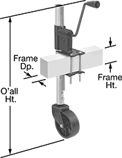 | 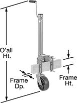 | 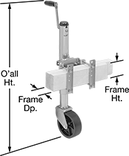 | 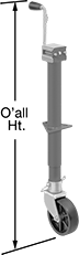 |
Style A | Style B | Style C | Style D |
For Frame | Mounting | Mounting Plate | |||||||||||||||||||||||||||||||||||||||||||||||||||||||||||||||||||||||||||||||||||||||||||||||||
|---|---|---|---|---|---|---|---|---|---|---|---|---|---|---|---|---|---|---|---|---|---|---|---|---|---|---|---|---|---|---|---|---|---|---|---|---|---|---|---|---|---|---|---|---|---|---|---|---|---|---|---|---|---|---|---|---|---|---|---|---|---|---|---|---|---|---|---|---|---|---|---|---|---|---|---|---|---|---|---|---|---|---|---|---|---|---|---|---|---|---|---|---|---|---|---|---|---|---|---|
Style | Weight Capacity | Ht. | Max. Lift | Overall Ht. | Ht. | Dp. | Handle Lg. | Body Material | For Hole Dia. | Fasteners Included | No. of Holes | Hole Lg. | Hole Wd. | Lg. | Wd. | Wheel Material | Each | ||||||||||||||||||||||||||||||||||||||||||||||||||||||||||||||||||||||||||||||||||
Clamp On Side Mount | |||||||||||||||||||||||||||||||||||||||||||||||||||||||||||||||||||||||||||||||||||||||||||||||||||
| A | 1/4 ton/750 lb. | 7 1/2" to 23 1/2" | 16" | 27 7/8" | 0" to 5" | 1 7/8" to 2 7/8" | 5 1/2" | Steel | — | Yes | — | — | — | — | — | Plastic | 2958T6 | 0000000 | |||||||||||||||||||||||||||||||||||||||||||||||||||||||||||||||||||||||||||||||||
| B | 1/2 ton/1,000 lb. | 10 13/16" to 25 1/2" | 14 11/16" | 33 7/8" | 3" to 5" | 2" to 3" | 6 1/8" | Steel | — | Yes | — | — | — | — | — | Plastic | 8792T31 | 000000 | |||||||||||||||||||||||||||||||||||||||||||||||||||||||||||||||||||||||||||||||||
Clamp On Side Mount with Locking Pin | |||||||||||||||||||||||||||||||||||||||||||||||||||||||||||||||||||||||||||||||||||||||||||||||||||
| C | 1/2 ton/1,200 lb. | 12 1/2" to 22 1/2" | 10" | 28 1/8" | 2" to 4" | 1 1/2" to 3" | 6" | Steel | — | Yes | — | — | — | — | — | Plastic | 8792T44 | 000000 | |||||||||||||||||||||||||||||||||||||||||||||||||||||||||||||||||||||||||||||||||
| C | 3/4 ton/1,500 lb. | 12 7/8" to 22 7/8" | 10" | 31 5/8" | 3" to 5" | 2" to 3" | 6 1/8" | Steel | — | Yes | — | — | — | — | — | Plastic | 8792T32 | 000000 | |||||||||||||||||||||||||||||||||||||||||||||||||||||||||||||||||||||||||||||||||
Bolt On/Through-Hole Mount | |||||||||||||||||||||||||||||||||||||||||||||||||||||||||||||||||||||||||||||||||||||||||||||||||||
| D | 1/2 ton/1,200 lb. | 8 5/8" to 21 1/2" | 12 7/8" | 35 5/8" | — | — | 6 1/2" | Steel | 2 1/4" | No | 3 | 7/16" | 13/16" | 5 1/8" | 4 1/4" | Plastic | 2933T62 | 000000 | |||||||||||||||||||||||||||||||||||||||||||||||||||||||||||||||||||||||||||||||||
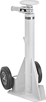
Scaffold Leveling Jacks
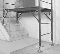 | 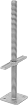 |
Swap these jacks with the base plates on your scaffold to create a level foundation on uneven ground. They adjust in increments less than an inch, so you can set each leg of your scaffold to the exact height you need. Made from galvanized steel, these jacks resist rust and hold up to outdoor use. For safety and stability, the top 6" of the threaded stud slides into the scaffold frame and isn’t usable.
Note: Leveling jacks meet OSHA and Cal/OSHA dimensional and construction standards. Check local, state, and federal codes, including OSHA, for safe set up and operating practices.
Hollow—Hollow jacks are lighter in weight than solid jacks, so they’re easier to handle.
Overall | Base | Thread | Base Mount | ||||||||||||||||||||||||||||||||||||||||||||||||||||||||||||||||||||||||||||||||||||||||||||||||
|---|---|---|---|---|---|---|---|---|---|---|---|---|---|---|---|---|---|---|---|---|---|---|---|---|---|---|---|---|---|---|---|---|---|---|---|---|---|---|---|---|---|---|---|---|---|---|---|---|---|---|---|---|---|---|---|---|---|---|---|---|---|---|---|---|---|---|---|---|---|---|---|---|---|---|---|---|---|---|---|---|---|---|---|---|---|---|---|---|---|---|---|---|---|---|---|---|---|---|---|
Wt. Cap., lb. | Max. Lift | Ht. | Wd. | Lg. | Wd. | For ID | Material | Size | Lg. | Fasteners Included | No. of Holes | Hole Dia. | Hole Ctr.-to-Ctr. | Wt., lb. | Specs. Met | Each | |||||||||||||||||||||||||||||||||||||||||||||||||||||||||||||||||||||||||||||||||||
Hollow | |||||||||||||||||||||||||||||||||||||||||||||||||||||||||||||||||||||||||||||||||||||||||||||||||||
| 5,300 | 18" | 24" | 9 3/8" | 5 5/16" | 5 5/16" | 1 1/2" | Galvanized Steel | 1 3/8"-4 | 16 9/16" | No | 4 | 1/2" | 3 5/16" | 6 | Cal/OSHA Compliant Title 8 Section 1646, OSHA Compliant 29 CFR 1926.451 | 7819N11 | 000000 | ||||||||||||||||||||||||||||||||||||||||||||||||||||||||||||||||||||||||||||||||||
Solid | |||||||||||||||||||||||||||||||||||||||||||||||||||||||||||||||||||||||||||||||||||||||||||||||||||
| 15,500 | 18" | 24" | 9 3/8" | 5 5/16" | 5 5/16" | 1 1/2" | Galvanized Steel | 1 3/8"-4 | 16 9/16" | No | 4 | 1/2" | 3 5/16" | 11 | Cal/OSHA Compliant Title 8 Section 1646, OSHA Compliant 29 CFR 1926.451 | 7819N12 | 00000 | ||||||||||||||||||||||||||||||||||||||||||||||||||||||||||||||||||||||||||||||||||
Leveling Micrometer Heads
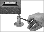 |  |
Precisely level heavy machines, surface plates, and other devices when accuracy is crucial. Turn the handle to adjust their height, even when under a machine.
Plain Thimble—Plain thimbles turn freely without friction or a stopping device and rely on operator feel for accurate measurements.
Overall | |||||||||||||||||||||||||||||||||||||||||||||||||||||||||||||||||||||||||||||||||||||||||||||||||||
|---|---|---|---|---|---|---|---|---|---|---|---|---|---|---|---|---|---|---|---|---|---|---|---|---|---|---|---|---|---|---|---|---|---|---|---|---|---|---|---|---|---|---|---|---|---|---|---|---|---|---|---|---|---|---|---|---|---|---|---|---|---|---|---|---|---|---|---|---|---|---|---|---|---|---|---|---|---|---|---|---|---|---|---|---|---|---|---|---|---|---|---|---|---|---|---|---|---|---|---|
Distance Measured Range, mm | Measuring Increments, mm | Point Angle | Spindle Face Material | Wt. Cap., lb. | Wd. | Ht. | Base Dia. | Handle Lg. | Features | Mfr. | Mfr. Model No. | Each | |||||||||||||||||||||||||||||||||||||||||||||||||||||||||||||||||||||||||||||||||||||||
Plain Thimble—Rotating Spindle | |||||||||||||||||||||||||||||||||||||||||||||||||||||||||||||||||||||||||||||||||||||||||||||||||||
| 60 to 75 | 0.01 | 90° | Steel | 850 | 4 19/32" | 2 3/8" | 2 17/32" | 3 11/32" | Handle | Mitutoyo | 7850 | 8614N11 | 0000000 | ||||||||||||||||||||||||||||||||||||||||||||||||||||||||||||||||||||||||||||||||||||||
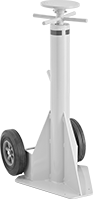
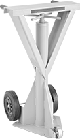
Ratchet Jack Stands
Rolling
 | 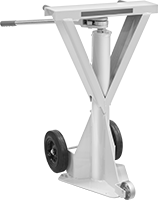 | 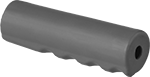 |
Two Axle-Mounted Wheels | Three Axle-Mounted Wheels | Replacement Grip |
 |  | 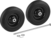 |
Replacement Handle | Replacement Saddle | Replacement Wheel Kit |
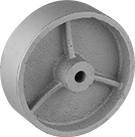 | ||
Replacement Wheel |
Saddle | Base | ||||||||||||||||||||||||||||||||||||||||||||||||||||||||||||||||||||||||||||||||||||||||||||||||||
|---|---|---|---|---|---|---|---|---|---|---|---|---|---|---|---|---|---|---|---|---|---|---|---|---|---|---|---|---|---|---|---|---|---|---|---|---|---|---|---|---|---|---|---|---|---|---|---|---|---|---|---|---|---|---|---|---|---|---|---|---|---|---|---|---|---|---|---|---|---|---|---|---|---|---|---|---|---|---|---|---|---|---|---|---|---|---|---|---|---|---|---|---|---|---|---|---|---|---|---|
Wt. Cap. | Holding Cap. | Ht. | Max. Lift | Dia. | Lg. | Wd. | Lg. | Wd. | Handle Lg. | Wheel Material | Features | Each | |||||||||||||||||||||||||||||||||||||||||||||||||||||||||||||||||||||||||||||||||||||||
Two Axle-Mounted Wheels | |||||||||||||||||||||||||||||||||||||||||||||||||||||||||||||||||||||||||||||||||||||||||||||||||||
| 20 ton/40,000 lb. | 50 ton/100,000 lb. | 39" to 51" | 12" | 8" | — | — | 16" | 17 5/8" | 20" | Rubber | Removable Handle | 8817T63 | 0000000 | ||||||||||||||||||||||||||||||||||||||||||||||||||||||||||||||||||||||||||||||||||||||
Three Axle-Mounted Wheels | |||||||||||||||||||||||||||||||||||||||||||||||||||||||||||||||||||||||||||||||||||||||||||||||||||
| 20 ton/40,000 lb. | 50 ton/100,000 lb. | 40" to 51" | 11 1/2" | — | 24" | 6" | 16" | 17 5/8" | 20" | Rubber, Steel | Removable Handle | 8817T67 | 000000 | ||||||||||||||||||||||||||||||||||||||||||||||||||||||||||||||||||||||||||||||||||||||
Screw Jack Stands
Stationary
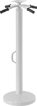 | |
Replacement Grip |
Saddle | ||||||||||
|---|---|---|---|---|---|---|---|---|---|---|
Wt. Cap. | Holding Cap. | Ht. | Max. Lift | Lg. | Wd. | Base Dia. | Each | |||
| 2 1/2 ton/5,000 lb. | 25 ton/50,000 lb. | 44" to 51" | 7" | 5" | 5" | 14" | 8817T61 | 0000000 | ||
Rolling
 |  | |
Two Axle-Mounted Wheels | Three Axle-Mounted Wheels | Replacement Grip |
| | |
Replacement Handle | Replacement Saddle | Replacement Wheel Kit |
| ||
Replacement Wheel |
Saddle | Base | ||||||||||||||||||||||||||||||||||||||||||||||||||||||||||||||||||||||||||||||||||||||||||||||||||
|---|---|---|---|---|---|---|---|---|---|---|---|---|---|---|---|---|---|---|---|---|---|---|---|---|---|---|---|---|---|---|---|---|---|---|---|---|---|---|---|---|---|---|---|---|---|---|---|---|---|---|---|---|---|---|---|---|---|---|---|---|---|---|---|---|---|---|---|---|---|---|---|---|---|---|---|---|---|---|---|---|---|---|---|---|---|---|---|---|---|---|---|---|---|---|---|---|---|---|---|
Wt. Cap. | Holding Cap. | Ht. | Max. Lift | Dia. | Lg. | Wd. | Lg. | Wd. | Handle Lg. | Wheel Material | Features | Each | |||||||||||||||||||||||||||||||||||||||||||||||||||||||||||||||||||||||||||||||||||||||
Two Axle-Mounted Wheels | |||||||||||||||||||||||||||||||||||||||||||||||||||||||||||||||||||||||||||||||||||||||||||||||||||
| 20 ton/40,000 lb. | 50 ton/100,000 lb. | 39" to 51" | 12" | 8" | — | — | 16" | 17 5/8" | 20" | Rubber | Removable Handle | 8817T62 | 0000000 | ||||||||||||||||||||||||||||||||||||||||||||||||||||||||||||||||||||||||||||||||||||||
Three Axle-Mounted Wheels | |||||||||||||||||||||||||||||||||||||||||||||||||||||||||||||||||||||||||||||||||||||||||||||||||||
| 20 ton/40,000 lb. | 50 ton/100,000 lb. | 40" to 51" | 11" | — | 24" | 6" | 16" | 17 5/8" | 20" | Rubber, Steel | Removable Handle | 8817T74 | 000000 | ||||||||||||||||||||||||||||||||||||||||||||||||||||||||||||||||||||||||||||||||||||||
Jack Stands—Not for Lifting
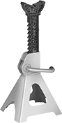 | 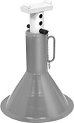 | 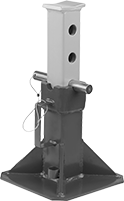 |
Style A | Style B | Style C |
After raising a load, add these steel stands for support.
Note: Do not raise or lower stands while under load. Always use stands in pairs and on a hard, flat surface.
Warning: Never use to support people or loads over people.
Locking-Handle Adjustment—Locking handles lock the ratchet bar in place to support the load.
Locking-Pin Adjustment—Locking pins are inserted through the riser to lock the bar in place.
Saddle | Base | ||||||||||||||||||||||||||||||||||||||||||||||||||||||||||||||||||||||||||||||||||||||||||||||||||
|---|---|---|---|---|---|---|---|---|---|---|---|---|---|---|---|---|---|---|---|---|---|---|---|---|---|---|---|---|---|---|---|---|---|---|---|---|---|---|---|---|---|---|---|---|---|---|---|---|---|---|---|---|---|---|---|---|---|---|---|---|---|---|---|---|---|---|---|---|---|---|---|---|---|---|---|---|---|---|---|---|---|---|---|---|---|---|---|---|---|---|---|---|---|---|---|---|---|---|---|
Style | Wt. Cap. per Pair | Ht. | Ht. Adjustment Increments | Lg. | Wd. | Dia. | Lg. | Wd. | Pair | ||||||||||||||||||||||||||||||||||||||||||||||||||||||||||||||||||||||||||||||||||||||||||
Locking-Handle Adjustment | |||||||||||||||||||||||||||||||||||||||||||||||||||||||||||||||||||||||||||||||||||||||||||||||||||
| A | 6 ton/12,000 lb. | 12" to 17 3/4" | 9/16" | 1" | 3 1/2" | — | 7 1/2" | 8 1/4" | 8059T31 | 0000000 | |||||||||||||||||||||||||||||||||||||||||||||||||||||||||||||||||||||||||||||||||||||||||
| A | 12 ton/24,000 lb. | 15 5/8" to 23 3/4" | 11/16" | 1 1/4" | 4 1/4" | — | 10 3/8" | 11 5/8" | 8059T32 | 000000 | |||||||||||||||||||||||||||||||||||||||||||||||||||||||||||||||||||||||||||||||||||||||||
Locking-Pin Adjustment | |||||||||||||||||||||||||||||||||||||||||||||||||||||||||||||||||||||||||||||||||||||||||||||||||||
| B | 12 ton/24,000 lb. | 19" to 29 1/2" | 1 1/2" | 3" | 6" | 15 7/8" | — | — | 8059T33 | 000000 | |||||||||||||||||||||||||||||||||||||||||||||||||||||||||||||||||||||||||||||||||||||||||
| C | 44 ton/88,000 lb. | 13 7/8" to 19 7/8" | 3" | 3" | 3 3/4" | — | 11" | 11" | 8059T35 | 000000 | |||||||||||||||||||||||||||||||||||||||||||||||||||||||||||||||||||||||||||||||||||||||||
