Body Material Body Material |
---|
|
|
For Use With For Use With |
---|
Connection Style Connection Style |
---|
![]() | ![]() |
Threaded | Compression |
![]() | |
Quick Clamp |
Maximum Pressure Maximum Pressure |
---|
System of Measurement System of Measurement |
---|
|
Overall Length Overall Length |
---|
Overall Height Overall Height |
---|
Valve Function Valve Function |
---|
|
Ball Material Ball Material |
---|
|
Maximum Temperature Maximum Temperature |
---|
|
Plug Material Plug Material |
---|
|
DFARS (Defense Acquisition Regulations Supplement) DFARS (Defense AcquisitionRegulations Supplement) |
---|
RoHS (Restriction of Hazardous Substances) RoHS (Restriction ofHazardous Substances) |
---|
|
REACH (Registration, Evaluation, Authorization and Restriction of Chemicals) REACH (Registration,Evaluation, Authorization and Restriction of Chemicals) |
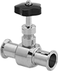
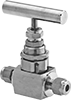
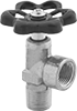
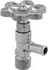
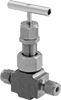
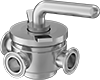
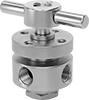
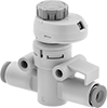
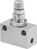
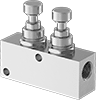
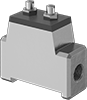
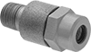
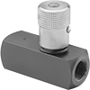
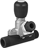
---|
|
About Actuated On/Off Valves
More
About On/Off Valves
More
Matching Flow Diagrams to Replace an Air Directional Control Valve
More
Choosing an Air Directional Control Valve
More
About Flow Control Valves
Also known as cylinder speed controls, flow control valves let you control the extension or retraction speed of your air cylinder. They regulate airflow as it passes from the valve's inlet to its outlet. Air flows freely in the opposite direction.
More
Threaded On/Off Valves for Natural Gas and Propane
- Valve Type: Plug
- For Use With: Natural Gas, Propane
Also known as plug valves, these are often used as a mainline shutoff in natural gas and propane pipelines.
T-handles resist accidental movement when snagged or bumped.
Lockable T-handles can be fixed in place using a padlock (not included) with a shackle diameter up to 1/2”.
Wrench-operated valves require a wrench (not included) to open and close the valve.
For technical drawings and 3-D models, click on a part number.

Pipe Size | Max. Pressure | Temperature Range, °F | End-to-End Lg. | Each | |
Bronze Body | |||||
---|---|---|---|---|---|
NPT Female × NPT Female | |||||
1/4 | 2 psi @ 70° F | 35° to 125° | 1 3/4" | 0000000 | 000000 |
1/4 | 25 psi @ 70° F | 35° to 125° | 1 7/8" | 00000000 | 00000 |
3/8 | 25 psi @ 70° F | 35° to 125° | 1 7/8" | 00000000 | 00000 |
1/2 | 5 psi @ 70° F | 35° to 125° | 2" | 0000000 | 00000 |
1/2 | 25 psi @ 70° F | 35° to 125° | 2 1/8" | 00000000 | 00000 |
3/4 | 5 psi @ 70° F | 35° to 125° | 2 3/8" | 0000000 | 00000 |
3/4 | 25 psi @ 70° F | 35° to 125° | 2 3/8" | 00000000 | 00000 |
1 | 2 psi @ 70° F | 35° to 125° | 2 3/4" | 0000000 | 00000 |
1 | 25 psi @ 70° F | 35° to 125° | 3" | 00000000 | 00000 |
1 1/4 | 2 psi @ 70° F | 35° to 125° | 3 1/4" | 0000000 | 00000 |

Pipe Size | Max. Pressure | Temperature Range, °F | End-to-End Lg. | For Max. Shackle Dia. | Each | |
Cast Iron Body | ||||||
---|---|---|---|---|---|---|
NPT Female × NPT Female | ||||||
1/2 | 175 psi @ 70° F | -20° to 150° | 2 7/8" | 1/2" | 00000000 | 000000 |
3/4 | 175 psi @ 70° F | -20° to 150° | 3 1/8" | 1/2" | 00000000 | 00000 |
1 | 175 psi @ 70° F | -20° to 150° | 3 3/8" | 1/2" | 00000000 | 00000 |
1 1/4 | 175 psi @ 70° F | -20° to 150° | 3 7/8" | 1/2" | 00000000 | 00000 |
1 1/2 | 175 psi @ 70° F | -20° to 150° | 4 5/8" | 1/2" | 00000000 | 000000 |
2 | 175 psi @ 70° F | -20° to 150° | 5 5/8" | 1/2" | 00000000 | 000000 |

Valves | Box Wrenches | ||||||
---|---|---|---|---|---|---|---|
Pipe Size | Max. Pressure | Temperature Range, °F | End-to-End Lg. | Each | Each | ||
Bronze Body | |||||||
NPT Female × NPT Female | |||||||
1/2 | 5 psi @ 70° F | 35° to 125° | 2" | 00000000 | 000000 | 0000000 | 000000 |
1/2 | 25 psi @ 70° F | 35° to 125° | 2 1/8" | 00000000 | 00000 | 0000000 | 00000 |
3/4 | 5 psi @ 70° F | 35° to 125° | 2 3/8" | 00000000 | 00000 | 0000000 | 00000 |
1 | 2 psi @ 70° F | 35° to 125° | 2 3/4" | 00000000 | 00000 | 0000000 | 00000 |
1 1/2 | 2 psi @ 70° F | 35° to 125° | 3 3/8" | 00000000 | 00000 | 000000 | 00 |
2 | 2 psi @ 70° F | 35° to 125° | 4 3/8" | 00000000 | 000000 | 000000 | 00 |
On/Off Valves with Compression Fittings
A compression sleeve bites into tubing as you tighten the nut, forming a strong seal.
Standard-port valves slightly restrict flow.
For technical drawings and 3-D models, click on a part number.

- Valve Type:
Brass Seal: Plug
All Other Valves: Ball - For Use With: See table

- Valve Type: Plug
- For Use With: Air, Water
Compact Threaded On/Off Valves for Fuel


- Valve Type: Plug
- For Use With: Diesel Fuel, Fuel Oil, Kerosene
- Seal Material: Buna-N Rubber Body
- Specifications Met: See table
A low-profile handle allows these valves to fit in low-clearance pipelines for diesel fuel, fuel oil, gasoline, and kerosene.
Pipe Size | Max. Pressure | Temperature Range, °F | End-to-End Lg. | Specifications Met | Each | |
Brass Body | ||||||
---|---|---|---|---|---|---|
NPTF Female × NPTF Female | ||||||
1/4 | 15 psi @ 70° F | -30° to 250° | 2 1/8" | UL Listed | 0000000 | 000000 |
1/4 | 30 psi @ 70° F | -30° to 250° | 2 1/8" | __ | 0000000 | 00000 |
NPTF Female × NPTF Male | ||||||
1/8 | 30 psi @ 70° F | -30° to 250° | 2" | __ | 0000000 | 00000 |
1/4 | 15 psi @ 70° F | -30° to 250° | 2 1/4" | UL Listed | 0000000 | 00000 |
1/4 | 30 psi @ 70° F | -30° to 250° | 2 1/4" | __ | 0000000 | 00000 |
3/8 | 15 psi @ 70° F | -30° to 250° | 2 7/16" | UL Listed | 0000000 | 00000 |
3/8 | 30 psi @ 70° F | -30° to 250° | 2 7/16" | __ | 0000000 | 00000 |
Multiport Threaded Diverting Valves


- Valve Type: Plug
- For Use With: Air, Argon, Helium, Krypton, Neon, Oil, Water, Xenon
- Seal Material: Fluoroelastomer Rubber
Divert the flow of compressed air and other media to multiple pieces of equipment. Turn the handle to direct flow to multiple outlet ports. Valves cannot shut off flow.
Valves with double L-pattern flow have two separate flow paths.
Valves with T-pattern flow direct flow from the inlet port to two of the three outlet ports at reduced capacity.
For technical drawings and 3-D models, click on a part number.
Sanitary Diverting Valves


Designed to direct the flow of liquids in food, dairy, and chemical-processing facilities, these valves can be fully disassembled for clean-out-of-place (COP) processes. They connect to your line with quick-clamp sanitary fittings, also known as tri-clamp connections, which are easier to remove and sanitize than threaded connections. You’ll need a gasket and clamp to connect them to another quick-clamp fitting (not included). These valves are 3-A certified to meet sanitary design standards.
Made of 316 stainless steel, these valves won’t corrode from frequent washdowns with harsh cleaners. The O-rings and seals are made from EPDM, which holds up to water, detergents, chemicals, and steam. They’re also FDA compliant for direct contact with food.
When you open or close these valves, a tapered plug slides in or out to direct the flow. Unlike ball valves, this plug design doesn’t have crevices between the seal and the valve body where contaminants could be trapped. Any surfaces that liquids touch are polished to extreme smoothness, so there’s nowhere for bacteria to hide. Liquids with abrasives, such as a smoothie with seeds, should not be used with this valve—if the surface of the plug is scratched or the seal is damaged, your liquids can be contaminated.
The T-pattern flow lets you direct liquids from the inlet to either outlet at full capacity, or to both outlets at reduced capacity. You can use any port as an inlet or an outlet—all three are full port and do not restrict flow. The long handle gives you plenty of leverage, so these valves are easy to open and close. The plug has a chrome plating to help it slide easily, and the seat is made from slippery PTFE to reduce friction from the handle, making sure these valves operate smoothly.
Flow coefficient (Cv) is the amount of water (in gallons per minute) at 60° F that will flow through a fully open valve with a difference of 1 psi between the inlet and the outlet.
For technical drawings and 3-D models, click on a part number.
For Tube | ||||||||||
---|---|---|---|---|---|---|---|---|---|---|
ID | OD | Flow Pattern | Flow Coefficient (Cv) | Max. Pressure | Temp. Range, °F | End-to-End Lg. | Surface Smoothness | Specifications Met | Each | |
316 Stainless Steel Body | ||||||||||
Quick Clamp × Quick Clamp × Quick Clamp | ||||||||||
1 3/8" | 1 1/2" | T-Pattern | Not Rated | 55 psi @ 70° F | -20° to 300° | 5 13/16" | 23 microinch | 3-A Certified 51-01, FDA Compliant 21 CFR 177.2600 | 00000000 | 0000000 |
1 7/8" | 2" | T-Pattern | Not Rated | 55 psi @ 70° F | -20° to 300° | 6 13/16" | 23 microinch | 3-A Certified 51-01, FDA Compliant 21 CFR 177.2600 | 00000000 | 000000 |
2 3/8" | 2 1/2" | T-Pattern | Not Rated | 55 psi @ 70° F | -20° to 300° | 8 1/4" | 23 microinch | 3-A Certified 51-01, FDA Compliant 21 CFR 177.2600 | 00000000 | 00000000 |
High-Purity Air-Driven Diverting Valves for Food and Beverage


- Valve Type: Plug
- For Use With: Beverage, Food
- Seal Material: EPDM Rubber
- Specifications Met: 3-A Certified 53-06
Often used in sanitary valve manifolds, these valves can be cleaned in place to eliminate the risk of cross contamination in food, beverage, and dairy lines. They are 3-A certified and electropolished to a 23 Ra finish for smooth internal surfaces that prevent product buildup and inhibit bacteria growth to maintain sanitary standards. All have sanitary quick-clamp fittings for easy disassembly. Valves operate on compressed air to automatically divert flow between ports more quickly than motor-driven valves. You must control the air to the actuator using either an electric pilot valve (not included) or a manual on/off valve (not included). Body is 316 stainless steel for excellent corrosion resistance. The actuator is secured to the valve body with a bracket for easy disassembly, maintenance, and repair.
Flow coefficient (Cv) is the amount of water (in gallons per minute) at 60° F that will flow through a fully open valve with a difference of 1 psi between the inlet and the outlet.
For technical drawings and 3-D models, click on a part number.
Air | ||||||||||||
---|---|---|---|---|---|---|---|---|---|---|---|---|
For Tube OD | Flow Pattern | Flow Coefficient (Cv) | Max. Pressure | Pressure Range, psi | Connection | Max. Temp., °F | Actuation Time | Valve Lg. | Port-to-Port Lg. | Interior Smoothness | Each | |
316 Stainless Steel Body—Quick Clamp × Quick Clamp × Quick Clamp | ||||||||||||
Single Acting: Air-to-Divert / Spring Return | ||||||||||||
1" | L-Pattern, U-Pattern | 15 | 175 psi @ 190° F | 70 to 115 | 1/4 NPT Female | 190° | 2 sec. | 4 1/2" | 2 1/4" | 23 Ra | 0000000 | 000000000 |
2" | L-Pattern, U-Pattern | 54 | 75 psi @ 190° F | 70 to 115 | 1/4 NPT Female | 190° | 2 sec. | 6 1/4" | 3 1/8" | 23 Ra | 0000000 | 00000000 |
3" | L-Pattern, U-Pattern | 119 | 70 psi @ 190° F | 70 to 115 | 1/4 NPT Female | 190° | 2 sec. | 6 7/8" | 3 7/8" | 23 Ra | 0000000 | 00000000 |
Inline Air Flow Control Valves with Flow Indicator


A flow indicator on these valves provides a relative measure of the air flowing through the valve, from off to full volume, similar to the volume dial on a speaker. The indicator’s numeric increments make it easy to set the valve to the same flow rate with each use. They adjust the volume of airflow to control the speed of air-powered equipment. Valves control flow in one direction as air moves from the inlet to the outlet. Air flows freely in the opposite direction. Typically, valves are installed to control flow as it exits the cylinder (meter out), but they may also be installed to control flow as it enters the cylinder (meter in). Designed to be mounted inline, they can be installed in an easy-to-reach location along your line. For the best control, mount them as close to the cylinder as possible to minimize the length of tubing or piping between the cylinder and the valve.
NPTF (Dryseal) threads are compatible with NPT threads.
Flow coefficient (Cv) is a measurement that indicates how much airflow can pass through a valve.
For technical drawings and 3-D models, click on a part number.
Inlet Pipe Size | Outlet Pipe Size | Flow Coefficient (Cv) | Min. Flow Rate | Max. Flow Rate | Max. Pressure, psi | Temp. Range, °F | Flow Adjustment Mechanism | Flow Control Type (ISO Designation) | Each | |
Brass Body | ||||||||||
---|---|---|---|---|---|---|---|---|---|---|
1/4 | 1/4 | 1.22 | 28 scfm @ 100 psi | 75 scfm @ 100 psi | 250 | 0° to 180° | Dial | Exiting Cylinder (Meter Out), Entering Cylinder (Meter In) | 00000000 | 000000 |
3/8 | 3/8 | 2.58 | 59 scfm @ 100 psi | 139 scfm @ 100 psi | 250 | 0° to 180° | Dial | Exiting Cylinder (Meter Out), Entering Cylinder (Meter In) | 00000000 | 00000 |
1/2 | 1/2 | 5.51 | 126 scfm @ 100 psi | 183 scfm @ 100 psi | 250 | 0° to 180° | Dial | Exiting Cylinder (Meter Out), Entering Cylinder (Meter In) | 00000000 | 00000 |
3/4 | 3/4 | 6.12 | 140 scfm @ 100 psi | 327 scfm @ 100 psi | 250 | 0° to 180° | Dial | Exiting Cylinder (Meter Out), Entering Cylinder (Meter In) | 00000000 | 000000 |
Inlet Pipe Size | Outlet Pipe Size | Flow Coefficient (Cv) | Min. Flow Rate | Max. Flow Rate | Max. Pressure, psi | Temp. Range, °F | Flow Adjustment Mechanism | Flow Control Type (ISO Designation) | Each | |
Aluminum Body | ||||||||||
---|---|---|---|---|---|---|---|---|---|---|
1/4 | 1/4 | 0.82 | 0 scfm @ 73 psi | 32.4 scfm @ 73 psi | 145 | 25° to 140° | Dial | Exiting Cylinder (Meter Out), Entering Cylinder (Meter In) | 00000000 | 000000 |
3/8 | 3/8 | 0.82 | 0 scfm @ 73 psi | 32.4 scfm @ 73 psi | 145 | 25° to 140° | Dial | Exiting Cylinder (Meter Out), Entering Cylinder (Meter In) | 00000000 | 00000 |
Air-Operated Air On/Off Valves

Also known as blocking valves, these valves are activated by an air signal to turn equipment on and off. They allow airflow when an air signal is applied to the air pilot. When the air supply is removed, the valve closes, trapping air in the system.
Valves with push-to-connect ports are for use with plastic or soft metal tubing. Insert tubing into the port.
Flow coefficient (Cv) is a measurement that indicates how much airflow can pass through a valve. When selecting between valves with the same port size, choose the valve with the higher flow coefficient to ensure it provides enough airflow to operate your system.
For technical drawings and 3-D models, click on a part number.
Air Pilot | Overall | |||||||||||||
---|---|---|---|---|---|---|---|---|---|---|---|---|---|---|
Inlet Pipe Size | Outlet Pipe Size | Air Pilot Thread Size | For Air Pilot Tube OD | Thread Type | Flow Coefficient (Cv) | Min. Flow Rate | Max. Flow Rate | Max. Pressure, psi | Temp. Range, °F | Lg. | Wd. | Ht. | Each | |
Brass Body | ||||||||||||||
1/8 | 1/8 | 10-32 | 5/32" | UNF | 0.64 | 0 scfm @ 100 psi | 15 scfm @ 100 psi | 145 | 0° to 160° | 1" | 1" | 2" | 00000000 | 000000 |
1/4 | 1/4 | 10-32 | 5/32" | UNF | 0.87 | 0 scfm @ 100 psi | 20 scfm @ 100 psi | 145 | 0° to 160° | 1" | 1" | 2" | 00000000 | 00000 |
3/8 | 3/8 | 10-32 | 5/32" | UNF | 2.06 | 0 scfm @ 100 psi | 45 scfm @ 100 psi | 145 | 0° to 160° | 1 3/8" | 1 1/8" | 2 3/16" | 00000000 | 000000 |
Overall | |||||||||||
---|---|---|---|---|---|---|---|---|---|---|---|
For Inlet Tube OD | Outlet Pipe Size | For Air Pilot Tube OD | Flow Coefficient (Cv) | Max. Flow Rate | Max. Pressure, psi | Temp. Range, °F | Lg. | Wd. | Ht. | Each | |
Brass Body | |||||||||||
1/4" | 1/8 | 5/32" | 0.64 | 15 scfm @ 100 psi | 145 | 0° to 160° | 1 1/8" | 1" | 2" | 00000000 | 000000 |
1/4" | 1/4 | 5/32" | 0.87 | 20 scfm @ 100 psi | 145 | 0° to 160° | 1 1/8" | 1" | 2" | 00000000 | 00000 |
3/8" | 3/8 | 5/32" | 2.06 | 45 scfm @ 100 psi | 145 | 0° to 160° | 1 3/8" | 1 1/8" | 2 3/16" | 00000000 | 000000 |
Modular Air Directional Control Valves with Air and Electrical Manifolds
Mix and match valve styles on one manifold to meet your control needs. Mount multiple valves to a manifold to reduce piping requirements and create multiple actions from a single pressure input. Add or remove valves as your needs change.
Manifolds connect multiple valves to a common input pressure source and exhaust port.
IP67 rated manifolds are dust tight and protected from temporary submersion.

Number of Ports | Overall | |||||||||||||||
---|---|---|---|---|---|---|---|---|---|---|---|---|---|---|---|---|
No. of Stations | No. of Flow Ports | Inlet | Outlet | Exhaust | For Inlet Tube OD | For Outlet Tube OD | Exhaust Connection Type | Voltage | Lg. | Wd. | Ht. | Mount Type | For DIN Rail Size | Mounting Fasteners Included | Each | |
Push-to-Connect Female Inlet × Push-to-Connect Female Outlet | ||||||||||||||||
M12 Plug (IP67) | ||||||||||||||||
4 | 12 | 2 | 8 | 2 | 3/8" | 1/4" | Push to Connect | 24V DC | 6" | 4 1/2" | 3" | Screw In, DIN Rail | 35 mm | Yes | 00000000 | 0000000 |
6 | 16 | 2 | 12 | 2 | 3/8" | 1/4" | Push to Connect | 24V DC | 7 1/4" | 4 1/2" | 3" | Screw In, DIN Rail | 35 mm | Yes | 00000000 | 000000 |
8 | 20 | 2 | 16 | 2 | 3/8" | 1/4" | Push to Connect | 24V DC | 8 1/2" | 4 1/2" | 3" | Screw In, DIN Rail | 35 mm | Yes | 00000000 | 000000 |