


System of Measurement System of Measurement |
|---|
|
Thread Type Thread Type |
|---|
Component Component |
|---|
| Ball Screw | |
 | Ball Nut |
| End Support | |
Length Length |
|---|
Material Material |
|---|
|
Threading Threading |
|---|
| Fully Threaded | |
Thread Direction Thread Direction |
|---|
 | |
Number of Thread Starts Number of Thread Starts |
|---|
|
RoHS (Restriction of Hazardous Substances) RoHS (Restriction ofHazardous Substances) |
|---|
|
Dynamic Thrust Load Capacity Dynamic Thrust Load Capacity |
|---|
|
Hardness Hardness |
|---|
|
DFARS (Defense Acquisition Regulations Supplement) DFARS (Defense AcquisitionRegulations Supplement) |
|---|
REACH (Registration, Evaluation, Authorization and Restriction of Chemicals) REACH (Registration,Evaluation, Authorization and Restriction of Chemicals) |
|---|
|
Selecting Compatible Lead Screws and Nuts
More
About Set Screws
More
Metric Ball Screws and Nuts
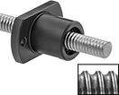
Internal ball bearings provide smooth low-friction travel in applications that require high speeds, accurate positioning, and repeatable movement. Also known as single-start ball screws and nuts, these have a single thread that runs the length of the screw. They operate with more torque than fast-travel ball screws and nuts. To ensure compatibility, select components that have the same thread size and travel distance per turn. Ball nuts are furnished with a tube to keep ball bearings in place. Do not remove the tube until you are ready to install the nuts onto the screws.
Travel distance per turn, also known as screw lead, is the distance a ball nut moves with one revolution of the ball screw.
![]() For technical drawings and 3-D models, click on a part number.
For technical drawings and 3-D models, click on a part number.
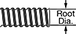
Root diameter indicates the diameter the ball screw will be after machining away the threads.
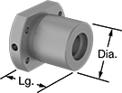
Ball Screw | Flange Ball Nut | |||||||||||||
|---|---|---|---|---|---|---|---|---|---|---|---|---|---|---|
| Thread Size | Lg., mm | Root Dia., mm | Tensile Strength, psi | Lg., mm | Dia., mm | No. of Thread Starts | Travel Distance per Turn, mm | Accuracy for Travel Distance per Turn | Hardness | Dynamic Thrust Load Cap., lbs. | Max. Backlash, mm | Temperature Range, °F | Each | |
Carbon Steel Ball Screw with Alloy Steel Flange Ball Nut | ||||||||||||||
| M6 | 150 | 5.3 | 21,000 | 21 | 13 | 1 | 1 | ±0.210 mm per 300 mm | Rockwell C58 | 150 | 0.05 | 5° to 175° | 0000000 | 0000000 |
| M6 | 250 | 5.3 | 21,000 | 21 | 13 | 1 | 1 | ±0.210 mm per 300 mm | Rockwell C58 | 150 | 0.05 | 5° to 175° | 000000 | 000000 |
| M8 | 150 | 6.6 | 21,000 | 28 | 20 | 1 | 2 | ±0.210 mm per 300 mm | Rockwell C58 | 470 | 0.05 | 5° to 175° | 0000000 | 000000 |
| M8 | 250 | 6.6 | 21,000 | 28 | 20 | 1 | 2 | ±0.210 mm per 300 mm | Rockwell C58 | 470 | 0.05 | 5° to 175° | 000000 | 000000 |
| M10 | 200 | 8.6 | 21,000 | 28 | 23 | 1 | 2 | ±0.210 mm per 300 mm | Rockwell C58 | 510 | 0.05 | 5° to 175° | 0000000 | 000000 |
| M10 | 300 | 8.6 | 21,000 | 28 | 23 | 1 | 2 | ±0.210 mm per 300 mm | Rockwell C58 | 510 | 0.05 | 5° to 175° | 000000 | 000000 |
| M12 | 200 | 10.6 | 21,000 | 30 | 25 | 1 | 2 | ±0.210 mm per 300 mm | Rockwell C58 | 560 | 0.05 | 5° to 175° | 000000 | 000000 |
| M12 | 300 | 10.6 | 21,000 | 30 | 25 | 1 | 2 | ±0.210 mm per 300 mm | Rockwell C58 | 560 | 0.05 | 5° to 175° | 0000000 | 000000 |
Root diameter indicates the diameter the ball screw will be after machining away the threads.
| Thread Size | Lg., mm | No. of Thread Starts | Travel Distance per Turn, mm | Accuracy for Travel Distance per Turn | Root Dia., mm | Hardness | Tensile Strength, psi | Temperature Range, °F | Each | |
Carbon Steel | ||||||||||
|---|---|---|---|---|---|---|---|---|---|---|
| M14 | 500 | 1 | 4 | ±0.210 mm per 300 mm | 11.5 | Rockwell C58 | 21,000 | 5° to 175° | 0000000 | 000000 |
| M14 | 1,000 | 1 | 4 | ±0.210 mm per 300 mm | 11.5 | Rockwell C58 | 21,000 | 5° to 175° | 0000000 | 000000 |
| M16 | 500 | 1 | 5 | ±0.210 mm per 300 mm | 13.5 | Rockwell C58 | 21,000 | 5° to 175° | 0000000 | 000000 |
| M16 | 1,000 | 1 | 5 | ±0.210 mm per 300 mm | 13.5 | Rockwell C58 | 21,000 | 5° to 175° | 000000 | 000000 |
| M20 | 500 | 1 | 5 | ±0.210 mm per 300 mm | 17.2 | Rockwell C58 | 21,000 | 5° to 175° | 0000000 | 000000 |
| M20 | 1,000 | 1 | 5 | ±0.210 mm per 300 mm | 17.2 | Rockwell C58 | 21,000 | 5° to 175° | 000000 | 000000 |
| M20 | 1,500 | 1 | 10 | ±0.210 mm per 300 mm | 16.4 | Rockwell C58 | 21,000 | 5° to 175° | 000000 | 000000 |
| M25 | 500 | 1 | 5 | ±0.210 mm per 300 mm | 22.2 | Rockwell C58 | 21,000 | 5° to 175° | 0000000 | 000000 |
| M25 | 1,000 | 1 | 5 | ±0.210 mm per 300 mm | 22.2 | Rockwell C58 | 21,000 | 5° to 175° | 0000000 | 000000 |
| M25 | 1,500 | 1 | 10 | ±0.210 mm per 300 mm | 20.2 | Rockwell C58 | 21,000 | 5° to 175° | 0000000 | 000000 |
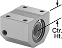
| Thread Size | Lg., mm | Wd., mm | Ht., mm | Center Ht., mm | No. of Thread Starts | Travel Distance per Turn, mm | Hardness | Dynamic Thrust Load Cap., lbs. | Max. Backlash, mm | Temperature Range, °F | Each | |
Alloy Steel | ||||||||||||
|---|---|---|---|---|---|---|---|---|---|---|---|---|
| M14 | 35 | 34 | 30 | 13 | 1 | 4 | Rockwell C58 | 1,200 | 0.1 | 5° to 175° | 0000000 | 0000000 |
| M16 | 36 | 42 | 32.5 | 16 | 1 | 5 | Rockwell C58 | 1,200 | 0.1 | 5° to 175° | 0000000 | 000000 |
| M20 | 35 | 48 | 39 | 17 | 1 | 5 | Rockwell C58 | 1,300 | 0.1 | 5° to 175° | 0000000 | 000000 |
| M20 | 58 | 48 | 46 | 18 | 1 | 10 | Rockwell C58 | 2,350 | 0.1 | 5° to 175° | 0000000 | 000000 |
| M25 | 35 | 60 | 45 | 20 | 1 | 5 | Rockwell C58 | 1,500 | 0.1 | 5° to 175° | 0000000 | 000000 |
| M25 | 94 | 60 | 55 | 23 | 1 | 10 | Rockwell C58 | 7,000 | 0.1 | 5° to 175° | 0000000 | 000000 |
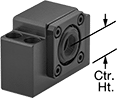
| Thread Size | Lg., mm | Dia., mm | Wd., mm, mm | Ht., mm | Thick., mm | No. of Thread Starts | Travel Distance per Turn, mm | Hardness | Dynamic Thrust Load Cap., lbs. | Max. Backlash, mm | Temperature Range, °F | Each | |
Alloy Steel | |||||||||||||
|---|---|---|---|---|---|---|---|---|---|---|---|---|---|
| M14 | 40 | 31 | 50 | 37 | 10 | 1 | 4 | Rockwell C58 | 1,200 | 0.1 | 5° to 175° | 0000000 | 0000000 |
| M16 | 40 | 34 | 54 | 40 | 10 | 1 | 5 | Rockwell C58 | 1,200 | 0.1 | 5° to 175° | 0000000 | 000000 |
| M20 | 40 | 40 | 60 | 46 | 10 | 1 | 5 | Rockwell C58 | 1,300 | 0.1 | 5° to 175° | 0000000 | 000000 |
| M20 | 64 | 52 | 82 | 64 | 12 | 1 | 10 | Rockwell C58 | 2,350 | 0.1 | 5° to 175° | 0000000 | 000000 |
| M25 | 40 | 43 | 67 | 50 | 10 | 1 | 5 | Rockwell C58 | 1,500 | 0.1 | 5° to 175° | 0000000 | 000000 |
| M25 | 98 | 60 | 96 | 72 | 15 | 1 | 10 | Rockwell C58 | 7,000 | 0.1 | 5° to 175° | 0000000 | 000000 |
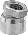
Metric End Supports for Lead Screws and Ball Screws
A set of ball bearings reduces friction and secures the end of a ball or lead screw. End supports handle radial loads (perpendicular to the lead screw) and thrust loads (parallel to the lead screw). Note: The end of your ball or lead screw must be machined before installing it into an end support.
![]() For technical drawings and 3-D models, click on a part number.
For technical drawings and 3-D models, click on a part number.
Combined Load Cap., lbs. | Top Mounting Holes | ||||||||||
|---|---|---|---|---|---|---|---|---|---|---|---|
| ID, mm | Ht., mm | Center Ht., mm | Wd., mm | Dp., mm | Static | Dynamic | Dia. | Ctr.-to-Ctr. Wd., mm | Temperature Range, °F | Each | |
For Combined Radial and Thrust Loads | |||||||||||
Carbon Steel | |||||||||||
| 12 | 43 | 25 | 60 | 34 | 730 | 1,450 | 6.6 | 46 | 0° to 160° | 0000000 | 0000000 |
| 15 | 48 | 28 | 70 | 38 | 890 | 1,700 | 6.6 | 54 | 0° to 160° | 0000000 | 000000 |
| 17 | 64 | 39 | 86 | 51 | 1,300 | 3,050 | 9 | 68 | 0° to 160° | 0000000 | 000000 |
Swiveling Tips for Screws and Threaded Studs
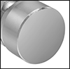
Attach to the end of a screw or threaded stud to apply uniform pressure on uneven and angled surfaces. Also known as toggle and swivel-foot pads.
![]() For technical drawings and 3-D models, click on a part number.
For technical drawings and 3-D models, click on a part number.
Metric Alloy Steel Low-Profile Swivel-Tip Set Screws
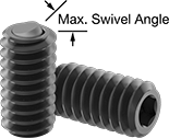
A low-profile flat-faced ball tip allows these set screw to be used in low-clearance applications. They're also known as ball-ended thrust screws. Length listed is the overall length.
![]() For technical drawings and 3-D models, click on a part number.
For technical drawings and 3-D models, click on a part number.
| Lg., mm | Tip Dia., mm | Max. Swivel Angle | Drive Size, mm | Hardness | Each | |
Alloy Steel | ||||||
|---|---|---|---|---|---|---|
M5 × 0.8 mm | ||||||
| 9.5 | 2.2 | 9° | 2.5 | Rockwell C39 | 000000000 | 00000 |
| 15.5 | 2.2 | 9° | 2.5 | Rockwell C39 | 000000000 | 0000 |
| 24.5 | 2.2 | 9° | 2.5 | Rockwell C39 | 000000000 | 0000 |
M6 × 1 mm | ||||||
| 16 | 3.2 | 9° | 3 | Rockwell C39 | 000000000 | 0000 |
| 20 | 3.2 | 9° | 3 | Rockwell C39 | 000000000 | 0000 |
| 25 | 3.2 | 9° | 3 | Rockwell C39 | 000000000 | 0000 |
M8 × 1.25 mm | ||||||
| 20 | 4.5 | 9° | 4 | Rockwell C39 | 000000000 | 00000 |
| 25 | 4.5 | 9° | 4 | Rockwell C39 | 000000000 | 00000 |
| 30 | 4.5 | 9° | 4 | Rockwell C39 | 000000000 | 00000 |
M10 × 1.5 mm | ||||||
| 16 | 6 | 9° | 5 | Rockwell C39 | 000000000 | 00000 |
| 25 | 6 | 9° | 5 | Rockwell C39 | 000000000 | 00000 |
| 35 | 6 | 9° | 5 | Rockwell C39 | 000000000 | 00000 |
M12 × 1.75 mm | ||||||
| 16 | 7.2 | 9° | 6 | Rockwell C39 | 000000000 | 00000 |
| 30 | 7.2 | 9° | 6 | Rockwell C39 | 000000000 | 00000 |
| 40 | 7.2 | 9° | 6 | Rockwell C39 | 000000000 | 00000 |