


Connection Location Connection Location |
|---|
| Bottom | Center Back | ||
For Use With For Use With |
|---|
|
|
Scale Scale |
|---|
Dial Type Dial Type |
|---|
 |  |
| Dry | Liquid Filled |


Measures Measures |
|---|
|
Case Material Case Material |
|---|
|
Connection Type Connection Type |
|---|
| Pipe | |
Connection Material Connection Material |
|---|
|
Connection Style Connection Style |
|---|
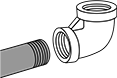 |
| Threaded |
Accuracy Scale Accuracy Scale |
|---|
|
RoHS (Restriction of Hazardous Substances) RoHS (Restriction ofHazardous Substances) |
|---|
|
REACH (Registration, Evaluation, Authorization and Restriction of Chemicals) REACH (Registration,Evaluation, Authorization and Restriction of Chemicals) |
|---|
|
About Pressure Gauges
More
About Pipe Size
More
About Pressure Transmitters
More
Pressure Gauges
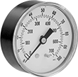

These are the most commonly used pressure gauges. Use them with pumps, filters, regulators, and in process lines to measure and display pressure.
Gauges with 304 stainless steel case or ABS plastic case have better corrosion resistance than gauges with brass or steel case.
![]() For technical drawings and 3-D models, click on a part number.
For technical drawings and 3-D models, click on a part number.
- For Use With: Air, Water, Hydraulic Fluid, Carbon Dioxide, and Natural Gas
- Accuracy: ±2% Mid Scale (Grade B)
- Mount with the dial face upright
Available Pressure Ranges | |||||
|---|---|---|---|---|---|
Pressure Range | Graduation Marks | Numeric Increments | |||
| psi | kPa | psi | kPa | psi | kPa |
| 0 to 30 | 0 to 200 | 1 | 5 | 5 | 50 |
| 0 to 60 | 0 to 400 | 2 | 10 | 10 | 100 |
| 0 to 100 | 0 to 700 | 2 | 20 | 20 | 100 |
| 0 to 160 | 0 to 1,100 | 5 | 20 | 20 | 200 |
| 0 to 200 | 0 to 1,400 | 5 | 50 | 40 | 200 |
| 0 to 300 | 0 to 2,000 | 10 | 50 | 50 | 500 |
| 0 to 600 | 0 to 4,000 | 20 | 100 | 100 | 1,000 |
| 0 to 1,000 | 0 to 7,000 | 20 | 200 | 200 | 1,000 |
Bottom Connection | Center Back Connection | ||||||||
|---|---|---|---|---|---|---|---|---|---|
| Dial Diameter | Pipe Size | Environment Temp. Range, °F | Process Temp. Range, °F | Case Color | Mounting Orientation | Each | Each | ||
BSPT Male | |||||||||
| 1 5/8" | 1/8 | -40° to 120° | -40° to 120° | Black | Upright | 0000000 | 000000 | 0000000 | 000000 |
| 2" | 1/4 | -40° to 120° | -40° to 120° | Black | Upright | 0000000 | 00000 | 0000000 | 00000 |
| 2 1/2" | 1/4 | -40° to 120° | -40° to 120° | Black | Upright | 0000000 | 00000 | 0000000 | 00000 |
Miniature Pressure Gauges

The small dial on these gauges allows for installation in tight spaces. Use them with pumps, filters, regulators, and in process lines to measure and display pressure.
Gauges with ABS plastic case are more corrosion resistant than brass-case gauges.
![]() For technical drawings and 3-D models, click on a part number.
For technical drawings and 3-D models, click on a part number.
- For Use With: Air, Water, Hydraulic Fluid, Ethyl Alcohol, Nitrogen, and Natural Gas
- Accuracy: ±5% Full Scale (Grade D)
Available Pressure Ranges | ||
|---|---|---|
| Pressure Range, psi | Graduation Marks, psi | Numeric Increments, psi |
| 0 to 60 | 5 | 10 |
| 0 to 100 | 5 | 20 |
| 0 to 160 | 10 | 40 |
| 0 to 200 | 10 | 40 |
| 0 to 300 | 25 | 50 |
Center Back Connection | |||||||
|---|---|---|---|---|---|---|---|
| Dial Diameter | Pipe Size | Environment Temp. Range, °F | Process Temp. Range, °F | Case Color | Mounting Orientation | Each | |
BSPT Male | |||||||
| 29/32" | 1/8 | -40° to 150° | -40° to 150° | Black | Any | 00000000 | 000000 |
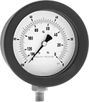
Vibration-Resistant Pressure Gauges
A liquid-filled dial reduces needle flutter for precise readings in high-vibration applications. Gauges are commonly used with pumps, filters, regulators, and in process lines to measure and display pressure. Mount them with the dial face upright.
Gauges with 304 stainless steel case and ABS plastic case have better corrosion resistance than gauges with brass case.
![]() For technical drawings and 3-D models, click on a part number.
For technical drawings and 3-D models, click on a part number.
- For Use With: Air, Water, Hydraulic Fluid, Carbon Dioxide, and Natural Gas
- Accuracy: ±1.5% Full Scale (Not Graded)
Available Pressure Ranges | |||||
|---|---|---|---|---|---|
Pressure Range | Graduation Marks | Numeric Increments | |||
| psi | bar | psi | bar | psi | bar |
BSPP Male | |||||
| 0 to 14.4 | 0 to 1 | 0.4 | 0.02 | 4 | 0.2 |
| 0 to 22.8 | 0 to 1.6 | 0.6 | 0.04 | 6 | 0.4 |
| 0 to 36 | 0 to 2.5 | 1 | 0.05 | 10 | 0.5 |
| 0 to 57.6 | 0 to 4 | 1.6 | 0.1 | 16 | 1 |
| 0 to 86 | 0 to 6 | 2 | 0.1 | 20 | 1 |
| 0 to 144 | 0 to 10 | 4 | 0.2 | 40 | 2 |
| 0 to 228 | 0 to 16 | 6 | 0.4 | 60 | 4 |
| 0 to 360 | 0 to 25 | 10 | 0.5 | 100 | 5 |
| 0 to 576 | 0 to 40 | 16 | 1 | 160 | 10 |
| 0 to 860 | 0 to 60 | 20 | 1 | 200 | 10 |
| 0 to 1,440 | 0 to 100 | 40 | 2 | 400 | 20 |
| 0 to 2,280 | 0 to 160 | 60 | 4 | 600 | 40 |
| 0 to 3,600 | 0 to 250 | 100 | 5 | 1,000 | 50 |
| 0 to 5,800 | 0 to 400 | 160 | 10 | 1,600 | 100 |
| 0 to 8,600 | 0 to 600 | 200 | 10 | 2,000 | 100 |
Absolute Pressure Gauges
Unlike other gauges that measure the difference between your system and the atmosphere, these give measurements relative to zero pressure. They’re often used in laboratory applications, and they are barometrically independent.
Stainless steel gauges have excellent corrosion resistance, so they can be used with more corrosive liquids and gasses than gauges with a brass connection and aluminum case.
![]() For technical drawings and 3-D models, click on a part number.
For technical drawings and 3-D models, click on a part number.
- For Use With: Air, Carbon Dioxide, Diesel Fuel, Ethyl Alcohol, Gasoline, Hydraulic Fluid, Natural Gas, Water
- Accuracy: ±1% Full Scale (Not Graded)
Available Pressure Ranges | ||
|---|---|---|
| Pressure Range, mbar | Numeric Increments, mbar | Graduation Marks, mbar |
| 0 to 25 | 5 | 0.5 |
| 0 to 60 | 10 | 1 |
| 0 to 160 | 50 | 5 |
| 0 to 600 | 100 | 10 |
| 0 to 1,000 | 200 | 20 |
Bottom Connection | ||||||
|---|---|---|---|---|---|---|
| Dial Diameter | Pipe Size | Environment Temp. Range, °F | Process Temp. Range, °F | Lens Material | Each | |
BSPP Male | ||||||
| 4" | 1/2 | 5° to 120° | 0° to 200° | Glass | 000000 | 000000000 |
Flush-Mount Pressure Transmitters
- For Use With: Air, Argon, Diesel Fuel, Hydraulic Fluid, Nitrogen, Water
- Accuracy: ±0.05%
- Pipe Connection: BSPP Male
- Housing Material: 316 Stainless Steel
- Connection Material: 316 Stainless Steel
- Diaphragm Material: Fluoroelastomer Rubber
- Temperature Range: -10° to 190° F
The diaphragm on these transmitters mounts flush with your system’s connection, leaving no room for thick liquids to clog or harden. They’re often used to monitor pressure in wastewater, paint, and adhesive-dispensing applications. Also known as transducers, they convert pressure to an electrical signal that can be interpreted by receiving devices, such as remote displays, programmable logic controllers, and motor speed controls. For your receiving device to interpret the signal from the transmitter, you will need to calibrate it for the transmitter's pressure range and output signal. As pressure increases, the output signal from the transmitter will increase. Transmitters will only provide accurate readings within the rated pressure range.
All are rated IP67 and IP69K, so they'll withstand temporary submersion as well as high-pressure, high-temperature washdowns. CE marked, they meet European safety standards.
Connect using two wires. The same wire is used to send a signal to the receiver and to power the transmitter. Current doesn’t lose signal over long distances and isn’t affected by electrical interference from other devices.
![]() For technical drawings and 3-D models, click on a part number.
For technical drawings and 3-D models, click on a part number.
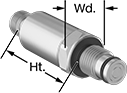
| Pressure Range, psi | Maximum Continuous Pressure, psi | Maximum Short-Term Pressure, psi | Input Voltage | Pipe Size | Ht. | Wd. | Environmental Rating | Each | |
4-20mA Current Output—2-Pole Micro M12 Connection | |||||||||
|---|---|---|---|---|---|---|---|---|---|
| 0-870 | 2,175 | 2,175 | 8.5-36V DC | 1/4 | 1 1/2" | 3/4" | IP67, IP69K | 0000000 | 0000000 |
| 0-1,450 | 3,625 | 3,625 | 8.5-36V DC | 1/4 | 1 1/2" | 3/4" | IP67, IP69K | 0000000 | 000000 |
| 0-2,320 | 5,800 | 5,800 | 8.5-36V DC | 1/4 | 1 1/2" | 3/4" | IP67, IP69K | 0000000 | 000000 |
| 0-3,625 | 9,060 | 9,060 | 8.5-36V DC | 1/4 | 1 1/2" | 3/4" | IP67, IP69K | 0000000 | 000000 |
| 0-5,800 | 11,580 | 11,580 | 8.5-36V DC | 1/4 | 1 1/2" | 3/4" | IP67, IP69K | 0000000 | 000000 |
Pressure and Vacuum Transmitters with Digital Display
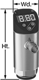
- For Use With: Air, Argon, Diesel Fuel, Hydraulic Fluid, Nitrogen, Water
- Accuracy: ±1%
- Pipe Connection Type: Threaded
- Housing Material: Glass-Reinforced Polyester
- Connection Material: 316L Stainless Steel
- Temperature Range: -10° to 175°F
Monitor and control vacuum pumps, air compressors, and hydraulics while viewing readings and warnings on the display. These transmitters, also called transducers, have two outputs, so you can program them to work as a transmitter, a switch, or both. When they reach their setpoint, they send electrical signals to your programmable logic controller (PLC) to trigger actions in your system. Adjust their reset point anywhere within the setpoint range. To change settings and receive error messages remotely from your PLC or computer, program one of the outputs to use IO Link. You need an IO-Link controller (not included) to connect to your interface.
Buttons on the display let you change your setpoint, measuring range, and other settings. To quickly tell the status of your process, you can program the color of the display to red and green. LEDs on the corners also notify you of your output’s switching status. Rotate the head to view the display from the best angle.
You must calibrate your PLC in order for it to interpret signals from these transmitters. As pressure increases, the output signal from the transmitter will increase. These transmitters only give accurate readings within the rated pressure or vacuum range.
All have an M12 plug to connect to M12 Connectors. When using both switching outputs and an IO-Link controller, they require four wires to connect. For their 4-20mA analog output, they need two wires to connect. View switch wiring diagrams by selecting a part number and clicking Product Detail.
To withstand wet environments, these transmitters have a 316L stainless steel connection and are IP rated. Their IP ratings also mean they’re dust tight and stand up to spraying water and brief submersion. UL and C-UL listed as well as CE marked, they meet strict American, Canadian, and European safety standards.
![]() For technical drawings and 3-D models, click on a part number.
For technical drawings and 3-D models, click on a part number.
Setpoint Range | Configurable Analog Transmitter/Digital Switch Output | Configurable Digital Switch Output | ||||||||||||||
|---|---|---|---|---|---|---|---|---|---|---|---|---|---|---|---|---|
| Pressure Range, psi | Vacuum Range, in. of Hg | Max. Continuous and Short-Term Pressure, psi | Pressure, psi | Vacuum, in. of Hg | Input Voltage | Pipe Size | Ht. | Wd. | No. of | Current | Signal Type | No. of | Signal Type | Scale | Each | |
BSPP Female | ||||||||||||||||
| 0-7.3 | 14.8-0 | 145 | 0-7.3 | 14.8-0 | 18-30V DC | 1/4 | 3 9/16" | 1 3/8" | 1 | 4-20mA | NPN, PNP | 1 | NPN, PNP | in. of H2O, kPa, mbar, psi | 0000000 | 0000000 |
| 0-14.5 | 1.4-0 | 145 | 0-14.5 | 1.4-0 | 18-30V DC | 1/4 | 3 9/16" | 1 3/8" | 1 | 4-20mA | NPN, PNP | 1 | NPN, PNP | in. of H2O, kPa, mbar, psi | 0000000 | 000000 |
| 0-14.5 | 29.5-0 | 145 | 0-14.5 | 29.5-0 | 18-30V DC | 1/4 | 3 9/16" | 1 3/8" | 1 | 4-20mA | NPN, PNP | 1 | NPN, PNP | in. of H2O, in. of Hg, kPa, mbar, psi | 0000000 | 000000 |
| 0-87 | 29.5-0 | 600 | 0-87 | 29.5-0 | 18-30V DC | 1/4 | 3 9/16" | 1 3/8" | 1 | 4-20mA | NPN, PNP | 1 | NPN, PNP | bar, MPa, psi | 0000000 | 000000 |
| 0-145 | 29.7-0 | 1,085 | 0-145 | 29.7-0 | 18-30V DC | 1/4 | 3 9/16" | 1 3/8" | 1 | 4-20mA | NPN, PNP | 1 | NPN, PNP | bar, MPa, psi | 0000000 | 000000 |
| 0-360 | 29.5-0 | 2,175 | 0-360 | 29.5-0 | 18-30V DC | 1/4 | 3 9/16" | 1 3/8" | 1 | 4-20mA | NPN, PNP | 1 | NPN, PNP | bar, MPa, psi | 0000000 | 000000 |
BSPP Male | ||||||||||||||||
| 0-7.3 | 14.8-0 | 145 | 0-7.3 | 14.8-0 | 18-30V DC | 1/4 | 3 11/16" | 1 3/8" | 1 | 4-20mA | NPN, PNP | 1 | NPN, PNP | bar, MPa, psi | 0000000 | 000000 |
| 0-14.5 | 1.4-0 | 145 | 0-14.5 | 1.4-0 | 18-30V DC | 1/4 | 3 11/16" | 1 3/8" | 1 | 4-20mA | NPN, PNP | 1 | NPN, PNP | bar, MPa, psi | 0000000 | 000000 |
| 0-14.5 | 29.5-0 | 145 | 0-14.5 | 29.5-0 | 18-30V DC | 1/4 | 3 11/16" | 1 3/8" | 1 | 4-20mA | NPN, PNP | 1 | NPN, PNP | in. of H2O, in. of Hg, kPa, mbar, psi | 0000000 | 000000 |
| 0-87 | 29.5-0 | 600 | 0-87 | 29.5-0 | 18-30V DC | 1/4 | 3 11/16" | 1 3/8" | 1 | 4-20mA | NPN, PNP | 1 | NPN, PNP | bar, MPa, psi | 0000000 | 000000 |
| 0-145 | 29.7-0 | 1,085 | 0-145 | 29.7-0 | 18-30V DC | 1/4 | 3 11/16" | 1 3/8" | 1 | 4-20mA | NPN, PNP | 1 | NPN, PNP | bar, MPa, psi | 0000000 | 000000 |
| 0-360 | 29.5-0 | 145 | 0-360 | 29.5-0 | 18-30V DC | 1/4 | 3 11/16" | 1 3/8" | 1 | 4-20mA | NPN, PNP | 1 | NPN, PNP | bar, MPa, psi | 0000000 | 000000 |
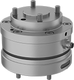
Robot-Ready Force Torque Sensors
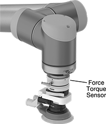
Mount these sensors between a robot arm and a tool for precise control during delicate tasks, such as sanding or assembling small parts. They constantly measure the force and torque your tool is applying to a workpiece, mimicking your sense of touch. As they measure the force and torque in six axes (three for force and three for torque), they send the data to your robot controller, which uses it to judge the tool's position and adjust the arm's movements. The constant communication between the sensor and controller helps you automate tasks that would normally require a person.
These sensors are UR+ Certified, which means they work seamlessly with Universal Robots (UR) systems. They have an ISO 50 mounting pattern to connect to most tools without an adapter. These sensors are more sensitive and accurate than built-in UR sensors, since they have an accuracy of ±2%. Switch between calibration settings for small and large loads for the most accurate measurements for the force in your application.
Install the data-recording software onto your teach pendant to integrate these sensors with your robot. The software helps you program, record, and control the forces of your assembly. LED status indicators show you whether the sensors are working, so you don't need to check your controller. They also have silicon strain gauges, which send a strong signal to your controller with very little distortion. Rated IP64, these sensors are dust-tight and protected from water splashing in all directions.
![]() For technical drawings and 3-D models, click on a part number.
For technical drawings and 3-D models, click on a part number.
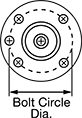
End of Robot Arm and Robot Tool | X- and Y-Axis Capacity | Z-Axis Capacity | ||||||
|---|---|---|---|---|---|---|---|---|
| Bolt Circle Dia., mm | Bolt Hole Thread Size | Force (Small / Large Load) | Torque (Small / Large Load) | Force (Small / Large Load) | Torque (Small / Large Load) | Includes | Each | |
12-30V DC Input Voltage | ||||||||
| 50 | M6 × 1 mm | 45 lbs. / 110 lbs. 20 kg / 50 kg 200 N / 500 N | 70 lbf-in. / 175 lbf-in. 80 kgf-cm / 200 kgf-cm 8 Nm / 20 Nm | 80 lbs. / 200 lbs. 36 kg / 90 kg 360 N / 900 N | 70 lbf-in. / 175 lbf-in. 80 kgf-cm / 200 kgf-cm 8 Nm / 20 Nm | 4 m M8 × M12 Sensor Cord 4 m Power/Data Cord with RJ45 and 3-Wire Connections Software Plug-In for Universal Robots | 0000000 | 000000000 |
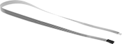
Compression Force Sensors for Tight Spaces
Thinner than a credit card, these force sensors fit into narrow spaces to measure the applied load between two surfaces. While they’re less accurate than larger alternatives such as load cells and handheld force gauges, these will fit almost anywhere. Place them within an industrial press to make sure it’s operating in a safe range, or form them to the contour of a forklift seat to test the concept of adding a smart switch that detects when an operator is sitting and ready to operate the forklift. Sensors should be calibrated before first use. Also known as force sensing resistors.
![]() For technical drawings and 3-D models, click on a part number.
For technical drawings and 3-D models, click on a part number.
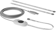
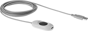
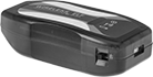
Kits come with software to analyze data from sensors. Kits with USB-A connection include a hub that plugs into your computer’s USB port. Kits with Wi-Fi connection use a hub that wirelessly connects to a computer or tablet within a sensing distance of 210 feet. The hub’s transmitter is certified 802.11b radio – 802.11b/g/n to meet IEEE standards for compatibility with other devices.
Additional sensors and hubs (both sold separately) expand the connection kits.
To connect 3-pin and 2-pin sensors into hubs with a USB connections, adapters (sold separately) are required.
Sensor | Hub | ||||||||||||||
|---|---|---|---|---|---|---|---|---|---|---|---|---|---|---|---|
| PC Connection Type | Sensor Connection Type | No. of Sensors Included | Capacity, English | Capacity, Newtons | Lg., mm | Wd., mm | Sensing Area Dia., mm | Sensing Distance, ft. | Battery Life, hrs. | No. of Batteries Included | Cord Lg., ft. | For Max. No. of Sensors | For Operating System | Each | |
| USB-A | Tab | 3 | 1 lbs. 25 lbs. 150 lbs. | 4.4 N 111 N 667 N | 229 | 14 | 9.53 | __ | __ | __ | 10 | 16 | Windows Vista Windows 7 Windows 8 Windows 8.1 Windows 10 | 0000000 | 000000000 |
| Wi-Fi | 3 Pin, 2 Pin | 3 | 1 lbs. 25 lbs. 150 lbs. | 4.4 N 111 N 667 N | 197 | 14 | 9.53 | 0-210 | 5 | 3 | __ | 16 | Windows 2000 Windows XP Windows Vista Windows 7 Windows 8 Windows 8.1 Windows 10 | 0000000 | 00000000 |
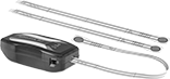
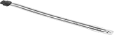
Expand your connection kit with additional sensors. Using more than one sensor allows you to monitor pressure at multiple points across a machine. Each sensor requires its own hub.
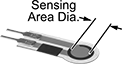
Sensors | ||||||||||||||||
|---|---|---|---|---|---|---|---|---|---|---|---|---|---|---|---|---|
Capacity | Measuring Increments | Extension Cables | ||||||||||||||
| English | Newtons | Accuracy | English | Newtons | Wd., mm | Thick., mm | Sensing Area Dia., mm | Sensing Area Lg., mm | Max. Current, mA | Input Voltage Range | Temp. Range, °F | Choose a Lg., mm | Each | Each | ||
Round—Tab Connection | ||||||||||||||||
| 1 lbs. | 4 N | ±3% | 0.1 lbs. | 0.01 N | 14 | 0.203 | 9.53 | __ | 2.5 | 0.25-1.25V DC | -40° to 140° | 229 | 0000000 | 000000 | 000000 | 00 |
| 25 lbs. | 111 N | ±3% | 0.1 lbs. | 0.01 N | 14 | 0.203 | 9.53 | __ | 2.5 | 0.25-1.25V DC | -40° to 140° | 229 | 0000000 | 00000 | 000000 | 00 |
| 150 lbs. | 667 N | ±3% | 0.1 lbs. | 0.01 N | 14 | 0.203 | 9.53 | __ | 2.5 | 0.25-1.25V DC | -40° to 140° | 229 | 0000000 | 00000 | 000000 | 00 |
Round—3-Pin Connection | ||||||||||||||||
| 1 lbs. | 4 N | ±3% | 0.1 lbs. | 0.01 N | 14 | 0.203 | 9.53 | __ | 2.5 | 0.25-1.25V DC | -40° to 140° | 000000 | 00000 | 0000000 | 000000 | |
| 25 lbs. | 111 N | ±3% | 0.1 lbs. | 0.01 N | 14 | 0.203 | 9.53 | __ | 2.5 | 0.25-1.25V DC | -40° to 140° | 000000 | 00000 | 0000000 | 00000 | |
| 50 lbs. | 222 N | ±3% | 0.1 lbs. | 0.01 N | 14 | 0.203 | 9.53 | __ | 2.5 | 0.25-1.25V DC | -40° to 400° | 000000 | 00000 | 0000000 | 00000 | |
| 100 lbs. | 445 N | ±3% | 0.1 lbs. | 0.01 N | 14 | 0.203 | 9.53 | __ | 2.5 | 0.25-1.25V DC | -40° to 140° | 000000 | 00000 | 0000000 | 00000 | |
| 150 lbs. | 667 N | ±3% | 0.1 lbs. | 0.01 N | 14 | 0.203 | 9.53 | __ | 2.5 | 0.25-1.25V DC | -40° to 140° | 191 | 0000000 | 00000 | 0000000 | 00000 |
Round—2-Pin Connection | ||||||||||||||||
| 1 lbs. | 4 N | ±3% | 0.1 lbs. | 0.01 N | 14 | 0.203 | 9.53 | __ | 2.5 | 0.25-1.25V DC | -40° to 185° | 25 | 0000000 | 00000 | 0000000 | 00000 |
| 4 lbs. | 18 N | ±3% | 0.1 lbs. | 0.01 N | 7.6 | 0.203 | 3.8 | __ | 2.5 | 0.25-1.25V DC | -40° to 140° | 16 | 0000000 | 00000 | 000000 | 00 |
| 25 lbs. | 111 N | ±3% | 0.1 lbs. | 0.01 N | 14 | 0.203 | 9.53 | __ | 2.5 | 0.25-1.25V DC | -40° to 140° | 25 | 0000000 | 00000 | 0000000 | 00000 |
| 25 lbs. | 111 N | ±3% | 0.1 lbs. | 0.01 N | 31.8 | 0.203 | 25.4 | __ | 2.5 | 0.25-1.25V DC | -40° to 140° | 25 | 0000000 | 00000 | 0000000 | 00000 |
| 100 lbs. | 445 N | ±3% | 0.1 lbs. | 0.01 N | 14 | 0.203 | 9.53 | __ | 2.5 | 0.25-1.25V DC | -40° to 140° | 25 | 0000000 | 00000 | 0000000 | 00000 |
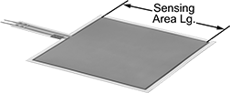
Square—2-Pin Connection | ||||||||||||||||
| 50 lbs. | 222 N | ±3% | 0.1 lbs. | 0.01 N | 55.9 | 0.203 | __ | 50.8 | 2.5 | 0.25-1.25V DC | -40° to 140° | 81 | 0000000 | 00000 | 0000000 | 00000 |
Adapters are required to connect 3-pin and 2-pin sensors into hubs with a USB connection.
Sensor Connection Type | |||
|---|---|---|---|
| Input | Output | Each | |
| 3-Pin and 2-Pin Female | Tab Male | 0000000 | 000000 |
Use male pin connectors to create a new male end on a trimmed sensor. Install a female end onto a sensor or another component with female pin connectors.