Filter by
For Use On
For Use With
Diameter
DFARS Specialty Metals

Collet Size
Shank Diameter
Spindle Speed
Operating System Compatibility
Machine Taper Number
For Holding
Overall Length
Most Likely Products
All Results
Fabricating and Machining


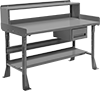
Containers, Storage, and Furniture
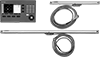
Measuring and Inspecting

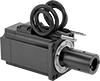
Power Transmission
Fastening and Joining