


Motor Frame Size Motor Frame Size | Show |
|---|
|
Motor Frame Size Motor Frame Size | Hide |
|---|
Overall Length Overall Length |
|---|
|
|
|
Component Component |
|---|
|
|
Maximum Speed Maximum Speed |
|---|
Shaft Diameter Shaft Diameter |
|---|
|
Maximum Holding Torque Maximum Holding Torque |
|---|
|
|
Mounting Orientation Mounting Orientation |
|---|
|
Overall Width Overall Width |
|---|
|
Voltage Voltage |
|---|
|
Mounting Style Mounting Style |
|---|
|
Power Source Power Source |
|---|
|
Resistance per Phase Resistance per Phase |
|---|
|
|
Direction of Operation Direction of Operation |
|---|
|
Thrust Load Capacity Thrust Load Capacity |
|---|
|
Inductance per Phase Inductance per Phase |
|---|
|
|
RoHS (Restriction of Hazardous Substances) RoHS (Restriction ofHazardous Substances) |
|---|
|
REACH (Registration, Evaluation, Authorization and Restriction of Chemicals) REACH (Registration,Evaluation, Authorization and Restriction of Chemicals) |
|---|
|
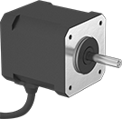
Stepper Motors
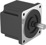
These stepper motors are good for precise, repetitive movements, such as those made by the head of a 3D printer. Similar to the hands of a clock, their shaft turns in small, equal increments. When the shaft stops, it holds its position even when a counteracting force is applied to the load. You can control the position of the load without having to configure encoders or sensors. All are bipolar hybrid stepper motors, which deliver greater torque, precision, and efficiency than other types of stepper motors.
When relative positioning is critical, such as coordinating motion in a multi-axis system, choose a motor with two shafts and mount an encoder (not included) on one of them. The encoder monitors the position of the shaft and reports back to the controller.
Holding torque is the force needed to move the shaft out of position when it is stationary. When the shaft is in motion, torque generally decreases as speed increases. Use a torque-speed curve to confirm which motor will work for your application. Click on a part number and select “Product Detail” to view the curve for a motor.
All motors require a controller and driver (not included).
![]() For technical drawings and 3-D models, click on a part number.
For technical drawings and 3-D models, click on a part number.
O'all | Shaft | ||||||||||||||
|---|---|---|---|---|---|---|---|---|---|---|---|---|---|---|---|
| Max. Holding Torque, in.-oz. | Max. Speed, rpm | Max. Current per Phase, A | Full Step Increment | Polarity | No. of Wire Leads | Lg. | Wd. | Ht. | Dia. | Lg. | Center to Base | Type | No. of Shafts | Each | |
NEMA 17 | |||||||||||||||
| 27 | 1,230 | 0.67 | 1.8° | Bipolar | 4 | 1.9" | 1.7" | 1.7" | 5mm | 24mm | 0.84" | Solid | 1 | 0000000 | 000000 |
| 39 | 900 | 0.62 | 1.8° | Bipolar | 4 | 2.1" | 1.7" | 1.7" | 5mm | 24mm | 0.84" | Solid | 1 | 0000000 | 00000 |
| 64 | 750 | 0.7 | 1.8° | Bipolar | 4 | 2.3" | 1.7" | 1.7" | 5mm | 24mm | 0.84" | Solid | 1 | 0000000 | 00000 |
| 71 | 2,250 | 2 | 1.8° | Bipolar | 4 | 2.5" | 1.7" | 1.7" | 5mm | 24mm | 0.84" | Solid | 1 | 0000000 | 00000 |
| 84 | 750 | 1.05 | 1.8° | Bipolar | 4 | 2.6" | 1.7" | 1.7" | 5mm | 24mm | 0.84" | D-Profile | 1 | 0000000 | 00000 |
| 115 | 1,000 | 2 | 1.8° | Bipolar | 4 | 3.8" | 1.7" | 1.7" | 5mm | 22mm | 0.84" | D-Profile | 2 | 00000000 | 000000 |
| 125 | 900 | 2 | 1.8° | Bipolar | 4 | 3.1" | 1.7" | 1.7" | 5mm | 24mm | 0.84" | D-Profile | 1 | 0000000 | 00000 |
Stepper Motors with Integrated Motion Control
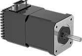
With a built-in controller and driver, these stepper motors come ready to program and operate. After connecting to a computer for initial setup, the controller can store and run programs on its own. The controller communicates to the driver which directs the motor’s shaft to move in small, equal increments. When the shaft stops, it holds its position even when a counteracting force is applied to the load. All are bipolar hybrid stepper motors, which deliver greater torque, precision, and efficiency than other types of stepper motors.
When relative positioning is critical, such as coordinating motion in a multi-axis system, choose a motor with an encoder. The encoder monitors the position of the shaft and reports back to the controller.
Holding torque is the force needed to move the shaft out of position when it is stationary. When the shaft is in motion, torque generally decreases as speed increases. Use a torque-speed curve to confirm which motor will work for your application. Click on a part number and select “Product Detail” to view the curve for a motor.
You can adjust the step resolution down to 1/256 of a full step, which translates to 51,200 microsteps per revolution. Increasing the number of steps directs an even more precise position and reduces the step-step-step motion to mimic a smooth, continuous rotation. The higher the number of step resolution settings, the greater the flexibility you have for determining the size of the motor’s step.
![]() For technical drawings and 3-D models, click on a part number.
For technical drawings and 3-D models, click on a part number.
O'all | Shaft | ||||||||||||||||
|---|---|---|---|---|---|---|---|---|---|---|---|---|---|---|---|---|---|
| Max. Holding Torque, in.-oz. | Max. Speed, rpm | Current per Phase, A | DC Voltage | Full Step Increment | Step Resolution | No. of Step Resolution Settings | Polarity | No. of Inputs/Outputs | Lg. | Wd. | Ht. | Dia. | Lg. | Center to Base | Type | Each | |
Motors/Controllers/Drivers | |||||||||||||||||
NEMA 17 | |||||||||||||||||
| 40.3 | 1,200 | 0.1-2 | 12-40 | 1.8° | 1; 1/2; 1/4; 1/8; 1/16; 1/32; 1/64; 1/128; 1/256 | 9 | Bipolar | 2 Digital Inputs/Outputs | 2.3" | 1.7" | 1.7" | 5mm | 22mm | 0.84" | Solid | 0000000 | 0000000 |
| 74.9 | 1,500 | 0.1-2 | 12-40 | 1.8° | 1; 1/2; 1/4; 1/8; 1/16; 1/32; 1/64; 1/128; 1/256 | 9 | Bipolar | 2 Digital Inputs/Outputs | 2.5" | 1.7" | 1.7" | 5mm | 22mm | 0.84" | Solid | 0000000 | 000000 |
| 85.4 | 750 | 0.1-2 | 12-40 | 1.8° | 1; 1/2; 1/4; 1/8; 1/16; 1/32; 1/64; 1/128; 1/256 | 9 | Bipolar | 2 Digital Inputs/Outputs | 2.8" | 1.7" | 1.7" | 5mm | 22mm | 0.84" | Solid | 0000000 | 000000 |
Motors/Controllers/Drivers/Encoders | |||||||||||||||||
NEMA 17 | |||||||||||||||||
| 31 | 3,000 | 0.1-2.2 | 12-48 | 1.8° | 1 to 1/256 | 25,501 | Bipolar | 1 Digital Output, 3 Digital Inputs, 1 Analog Input | 3.7" | 1.7" | 3" | 5mm | 22mm | 0.84" | D-Profile | 00000000 | 000000 |
| 54 | 3,000 | 0.1-2.2 | 12-48 | 1.8° | 1 to 1/256 | 25,501 | Bipolar | 1 Digital Output, 3 Digital Inputs, 1 Analog Input | 3.9" | 1.7" | 3" | 5mm | 22mm | 0.84" | D-Profile | 00000000 | 000000 |
| 68 | 3,000 | 0.1-2.2 | 12-48 | 1.8° | 1 to 1/256 | 25,501 | Bipolar | 1 Digital Output, 3 Digital Inputs, 1 Analog Input | 4.2" | 1.7" | 3" | 5mm | 22mm | 0.84" | D-Profile | 00000000 | 000000 |
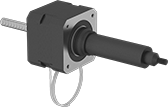
Stepper Motors with Linear Actuation
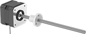
Instead of a shaft, these stepper motors have a lead screw that converts rotational motion to linear motion. Moving in increments smaller than the thickness of a sheet of paper, they're ideal for applications that require fine motion control, such as positioning electrical components on a circuit board. They move in equal steps and hold their position when stationary, so they do not require encoders, sensors, or other position feedback devices. The lead screw is built into the motor, so there are fewer points of failure than systems that use a shaft coupling to connect the lead screw. All are bipolar hybrid stepper motors, which deliver greater torque, precision, and efficiency than other types of stepper motors.
External lead screw stepper motors work similar to a traditional linear motion system; attach the load to the flanged nut, which travels back and forth along the lead screw.
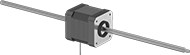
Pass-through lead screw stepper motors give you the most design versatility because there are two ways to move your load: on the motor body or on the ends of the lead screw. The motor moves when the lead screw is fixed or the lead screw moves when the motor body is fixed.
Travel distance per full step determines the control you have over the motor’s positioning. The smaller the measurement, the finer positioning control you have, but the more steps it will take to go the same distance.
Dynamic load capacity is the maximum load a motor can move. If you increase the speed, the dynamic load capacity decreases. Click on a part number and select "Product Detail" to view the load-speed chart and confirm the motor will work for your application.
All motors require a driver and controller (not included).
![]() For technical drawings and 3-D models, click on a part number.
For technical drawings and 3-D models, click on a part number.
O'all | ||||||||||||||
|---|---|---|---|---|---|---|---|---|---|---|---|---|---|---|
| Travel Distance per Full Step | Travel Lg. | Dynamic Load Capacity, lbs. | Max. Speed, in./sec. | Max. Current per Phase | Full Step Increment | Polarity | No. of Wire Leads | Lg. | Wd. | Ht. | Lead Screw Lg. | Thread Size | Each | |
External Lead Screw | ||||||||||||||
NEMA 17 | ||||||||||||||
| 0.000625" | 5.2" | 50 | 1.2 | 1.5A | 1.8° | Bipolar | 4 | 7.3" | 1.7" | 1.7" | 6" | 1/4"-16 | 0000000 | 0000000 |
| 0.000625" | 5.2" | 75 | 1.1 | 2.6A | 1.8° | Bipolar | 4 | 7.9" | 1.7" | 1.7" | 6" | 1/4"-16 | 0000000 | 000000 |
| 0.000625" | 11.2" | 50 | 1.2 | 1.5A | 1.8° | Bipolar | 4 | 13.3" | 1.7" | 1.7" | 12" | 1/4"-16 | 0000000 | 000000 |
| 0.000625" | 11.2" | 75 | 1.1 | 2.6A | 1.8° | Bipolar | 4 | 13.9" | 1.7" | 1.7" | 12" | 1/4"-16 | 0000000 | 000000 |
| 0.00125" | 5.2" | 25 | 2 | 1.5A | 1.8° | Bipolar | 4 | 7.3" | 1.7" | 1.7" | 6" | 1/4"-16 | 0000000 | 000000 |
| 0.00125" | 5.2" | 60 | 2.1 | 2.6A | 1.8° | Bipolar | 4 | 7.9" | 1.7" | 1.7" | 6" | 1/4"-16 | 0000000 | 000000 |
| 0.00125" | 11.2" | 25 | 2 | 1.5A | 1.8° | Bipolar | 4 | 13.3" | 1.7" | 1.7" | 12" | 1/4"-16 | 0000000 | 000000 |
| 0.00125" | 11.2" | 60 | 2.1 | 2.6A | 1.8° | Bipolar | 4 | 13.9" | 1.7" | 1.7" | 12" | 1/4"-16 | 0000000 | 000000 |
Pass-Through Lead Screw | ||||||||||||||
NEMA 17 | ||||||||||||||
| 0.000625" | 10.1" | 75 | 1.1 | 2.6A | 1.8° | Bipolar | 4 | 12.3" | 1.7" | 1.7" | 12" | 1/4"-16 | 0000000 | 000000 |
| 0.000625" | 10.6" | 50 | 1.2 | 1.5A | 1.8° | Bipolar | 4 | 12.3" | 1.7" | 1.7" | 12" | 1/4"-16 | 0000000 | 000000 |
| 0.00125" | 10.1" | 60 | 2.1 | 2.6A | 1.8° | Bipolar | 4 | 12.3" | 1.7" | 1.7" | 12" | 1/4"-16 | 0000000 | 000000 |
| 0.00125" | 10.6" | 25 | 2 | 1.5A | 1.8° | Bipolar | 4 | 12.3" | 1.7" | 1.7" | 12" | 1/4"-16 | 0000000 | 000000 |
Wet-Location Stepper Motors
To precisely position loads in automated systems that are frequently rinsed, these stepper motors are IP65 rated to seal out water. Their shaft turns in small, equal increments, similar to the hands of a clock. When the shaft stops, it holds its position even when force is applied to the load. This means you don’t need to configure encoders or sensors to control the position of the load. All are hybrid bipolar stepper motors, so they have more torque, precision, and efficiency than other stepper motors.
Holding torque is the force needed to move the shaft out of position when it’s stationary. When the shaft is in motion, torque generally decreases as speed increases. Use a torque-speed curve to confirm which motor will work for your application. Click on a part number and select “Product Detail” to view the curve for a motor.
These stepper motors require a controller and a driver (not included).
![]() For technical drawings and 3-D models, click on a part number.
For technical drawings and 3-D models, click on a part number.
Overall | Shaft | |||||||||||||||
|---|---|---|---|---|---|---|---|---|---|---|---|---|---|---|---|---|
| Maximum Holding Torque, in.-oz. | Maximum Speed, rpm | Maximum Current per Phase, A | Full Step Increment | Polarity | Number of Wire Leads | Length | Width | Height | Diameter | Length | Center to Base | Type | Number of Shafts | Environmental Rating | Each | |
NEMA 17 | ||||||||||||||||
| 84 | 2,500 | 2.1 | 1.8° | Bipolar | 4 | 2.9" | 1.7" | 1.7" | 5mm | 22mm | 0.84" | Solid | 1 | IP65 | 0000000 | 0000000 |
Compact Stepper Motor Actuators
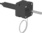
A lead screw that converts rotational motion to linear motion sits inside the motor body for a compact footprint. Add a driver and controller to these actuators to repeatedly position loads with speed and precision. Moving in small, equal steps, these actuators are good for jobs requiring fine motion control, such as positioning electrical components on a circuit board. Their load stays in position even when a counteracting force is applied, so you don’t need encoders, sensors, or other position feedback devices.
All have bipolar hybrid stepper motors, which deliver greater torque, precision, and efficiency than other types of stepper motors. The splined shaft keeps the rod from rotating as it extends and retracts.
Travel distance per full step determines the control you have over the actuator's positioning. The smaller the measurement, the finer positioning control you have, but the more steps it will take to go the same distance.
Dynamic load capacity is the maximum load an actuator can move. If you increase the speed, the dynamic load capacity decreases. Click on a part number and select "Product Detail" to view the load-speed chart and confirm the actuator will work for your application.
![]() For technical drawings and 3-D models, click on a part number.
For technical drawings and 3-D models, click on a part number.
Dynamic Load Capacity, lbs. | ||||||||||||
|---|---|---|---|---|---|---|---|---|---|---|---|---|
| Travel Distance per Full Step | Stroke Lg. | Pull | Push | Max. Speed, in./sec. | Max. Current per Phase, A | Full Step Increment | Polarity | No. of Wire Leads | Extension Rod Type | Retracted Lg. | Each | |
NEMA 17 | ||||||||||||
| 0.00015625" | 2" | 50 | 50 | 0.4 | 1.5 | 1.8° | Bipolar | 4 | Nonrotating | 6" | 0000000 | 0000000 |
| 0.000625" | 2" | 50 | 50 | 1.25 | 1.5 | 1.8° | Bipolar | 4 | Nonrotating | 6" | 0000000 | 000000 |
| 0.000625" | 2" | 75 | 75 | 1 | 2.6 | 1.8° | Bipolar | 4 | Nonrotating | 6 3/8" | 0000000 | 000000 |
| 0.00125" | 2" | 60 | 60 | 2.25 | 2.6 | 1.8° | Bipolar | 4 | Nonrotating | 6 3/8" | 0000000 | 000000 |