


About Precision Flow-Adjustment Valves
More
About Process Pumps
More
About Drum Pumps
More
How to Prime Your Pump
More
How to Determine Feet of Head
More
Selectable-Flow-Rate Easy-Stroke Drum Pumps for Water and Chemicals
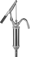
These pumps have a selectable flow rate, so you can adjust flow for different dispensing applications. A lever handle maximizes output with each stroke for low-effort dispensing.
Whenever working with flammable liquids, always bond and ground your application for static control. For more information about bonding and grounding, see Sections 1910.106 and 1910.107 of the Federal OSHA Code or see bonding and grounding equipment.
Temp. Range, °F | Intake | |||||||||||
|---|---|---|---|---|---|---|---|---|---|---|---|---|
| Flow Rate, oz./stroke | For Container Size, gal. | Max. Viscosity, cP | Min. | Max. | For Drum Opening Size | Includes | Tube OD | Tube Lg. | For Discharge Tube ID | Spout Type | Each | |
Stainless Steel Intake Tube and Housing | ||||||||||||
| 6, 8, 10, 12 | 15-55 | 2,000 | Not Rated | 140° | 1 1/2 NPT, 2 NPT | Drum Connector | 1 1/8" | 18 1/2"-32 1/2" | 11/16" | Removable | 0000000 | 0000000 |
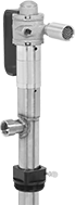
Air-Powered Drum Pumps for Water, Oil, Coolants, and Chemicals
These pumps have a nonsparking air-powered motor for applications where electricity is unavailable or dangerous. Install an air line filter/lubricator to ensure efficiency and reduce wear on the pump. They're often used with ammonia, etching and cleaning solutions, and other caustics.
Temp. Range, °F | Air Connection | Intake | Discharge (Pump Body) | |||||||||||||||
|---|---|---|---|---|---|---|---|---|---|---|---|---|---|---|---|---|---|---|
| Flow Rate, gpm | For Container Size, gal. | Max. Viscosity, cP | Min. | Max. | Air Pressure Range, psi | Air Consumption, cfm | For Drum Opening Size | Includes | Pipe Size | Gender | Thread Type | Tube OD | Tube Lg. | Pipe Size | Gender | Thread Type | Each | |
| 14 | 55 | 1,500 | -30° | 300° | 40-80 | 27 | 2 NPT | Drum Connector | 1/8 | Female | NPT | 1 1/2" | 39" | 3/4 | Female | NPT | 00000000 | 0000000 |
Air-Powered Drum Pumps for Flammable Liquid
These pumps have a motor that is rated for IEC Zone 1, Groups IIB and IIA; and IEC Zone 21, Groups IIIC, IIIB, and IIIA hazardous locations with flammable gases and vapors, so they can be used with liquids such as acetone, ethanol, methyl ethyl ketone (MEK), xylene, and mineral spirits. Motor is nonsparking for use in applications where electricity is unavailable or dangerous. Install an air line filter/lubricator to ensure efficiency and reduce wear on the pump.
Always bond and ground your application for static control. For more information about bonding and grounding, see Sections 1910.106 and 1910.107 of the Federal OSHA Code or see bonding and grounding equipment.
Temp. Range, °F | Air Connection | Intake | Discharge | ||||||||||||||
|---|---|---|---|---|---|---|---|---|---|---|---|---|---|---|---|---|---|
| Flow Rate, gpm | For Container Size, gal. | Max. Viscosity, cP | Min. | Max. | Air Pressure Range, psi | Air Consumption, cfm | For Drum Opening Size | Includes | Pipe Size | Gender | Thread Type | Tube OD | Tube Lg. | Tube Connection Type | For Tube ID | Each | |
| 26 | 55 | 1,100 | -40° | 210° | 44-87 | 53 | 2 NPT | Drum Connector | 3/8 | Female | NPT | 1 5/8" | 39" | Barbed | 1" | 0000000 | 000000000 |
| 26 | 55 | 1,100 | -40° | 210° | 44-87 | 53 | 2 NPT | Drum Connector | 3/8 | Female | NPT | 1 5/8" | 47" | Barbed | 1" | 0000000 | 00000000 |
| 53 | 55 | 1,000 | -40° | 210° | 44-87 | 53 | 2 NPT | Drum Connector | 3/8 | Female | NPT | 1 5/8" | 39" | Barbed | 1" | 0000000 | 00000000 |
| 53 | 55 | 1,000 | -40° | 210° | 44-87 | 53 | 2 NPT | Drum Connector | 3/8 | Female | NPT | 1 5/8" | 47" | Barbed | 1" | 0000000 | 00000000 |
PVDF Extended-Life Air-Powered Drum Pumps for Chemicals
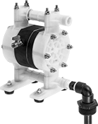
A chemical- and impact-resistant PVDF housing stands up to aggressive chemicals such as methyl ethyl ketone (MEK) and xylene. Also known as diaphragm pumps, they have few moving parts that can fail for a long service life. Install an air line filter/lubricator to ensure efficiency and reduce wear on the pump.
Repair kits include O-rings, valves, and diaphragms.
Temp. Range, °F | Air Connection | Intake | Discharge | ||||||||||||||||
|---|---|---|---|---|---|---|---|---|---|---|---|---|---|---|---|---|---|---|---|
| Flow Rate, gpm | For Container Size, gal. | Max. Viscosity, cP | Min. | Max. | Air Pressure, psi | Air Consumption, cfm | For Drum Opening Size | Pipe Size | Gender | Thread Type | Pipe Size | Gender | Thread Type | Tube Lg. | Pipe Size | Gender | Thread Type | Each | |
| 13 | 55 | 3,000 | 40° | 210° | 100 | 12 | 2 NPT | 1/4 | Female | NPT | 1/2 | Female | NPT | 36" | 1/2 | Female | NPT | 0000000 | 000000000 |
| Repair Kit | 00000000 | Each | 0000000 |
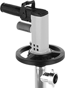
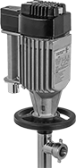
Hazardous Location Electric Drum Pumps
for Water, Oil, Coolants, and Chemicals
These pumps quickly empty drum contents by moving 48 gallons of liquid per minute. They are often used with lubricating oil as well as with chemicals such as detergents and etching and cleaning solutions. Their electric motors are explosion proof and UL listed for Class I, Divisions 1 and 2, Groups C and D; and Class II, Division 2, Groups F and G environments where flammable gases and combustible dust may be present.
Temp. Range, °F | Intake | Discharge | |||||||||||||
|---|---|---|---|---|---|---|---|---|---|---|---|---|---|---|---|
| Flow Rate, gpm | Discharge Pressure, psi | For Container Size, gal. | Max. Viscosity, cP | Min. | Max. | Horsepower | Current, A | For Drum Opening Size | Tube OD | Tube Lg. | Tube Connection Type | For Tube ID | Thermal Protection | Each | |
120V AC, Single Phase | |||||||||||||||
Hardwire | |||||||||||||||
| 48.5 | 14 | 55 | 300 | -40° | 210° | 1/2 hp | 5.3 | 41 mm | 1 5/8" | 39" | Barbed | 1" | With Thermal Overload Protection | 00000000 | 000000000 |
Electric Drum Pump Systems for Water, Oil, Coolants, and Chemicals
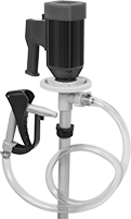
Including nozzles and connectors, these pumps come with everything you need to start pumping. All include a pump assembly, 1" ID hose, dispensing nozzle, drum connector, and storage bracket.
Pumps with a 316 stainless steel housing are often used with fuel, acetone, methyl ethyl ketone (MEK), xylene, and mineral spirits. Their motors are rated IP55 and are CSA certified for use in Class I, Divisions 1 and 2, Group D hazardous environments with flammable gases and vapors.
Temp. Range, °F | Intake | Discharge | ||||||||||||||
|---|---|---|---|---|---|---|---|---|---|---|---|---|---|---|---|---|
| Flow Rate, gpm | Discharge Pressure, psi | For Container Size, gal. | Max. Viscosity, cP | Min. | Max. | Horsepower | Current, A | For Drum Opening Size | Tube OD | Tube Lg. | Tube ID | Tube OD | Tube Lg. | Environmental Rating | Each | |
120V AC, Single Phase—Hardwire | ||||||||||||||||
316 Stainless Steel Housing | ||||||||||||||||
| 18 | 15 | 55 | 1,000 | Not Rated | 175° | 1 1/3 hp | 9.1 | 2 NPT | 1 1/2" | 39" | 1" | 1 1/4" | 72" | NEC Class I Divisions 1, 2 Group D IP55 | 0000000 | 000000000 |
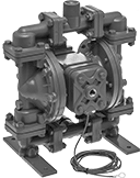
PTFE Air-Powered Transfer Pumps for Harsh Chemicals
With all PTFE wetted parts, these pumps offer the best chemical resistance of all our air-powered transfer pumps and can handle solvents and petroleum-based fluids that PVDF pumps can’t. Pumps are self-priming, which means they create a suction force to draw liquid upward to fill the pump chamber. All can run dry.
Fluid-side maintenance kits include diaphragms, check valve balls, and seals.
Air-motor maintenance kits include seals, O-rings, gaskets, retaining rings, and an air valve spool.

Overall | |||||||||
|---|---|---|---|---|---|---|---|---|---|
| Max. Flow Rate, gpm | Air Consumption, cfm | Air Connection (NPT) | Intake Pipe Connection (NPT) | Discharge Pipe Connection (NPT) | Lg. | Wd. | Ht. | Each | |
231 Max. ft. of Head—100 psi Max. Discharge Pressure | |||||||||
| 2.5 | 4.8 | 1/8 Female | 1/4 Female | 1/4 Female | 3 3/8" | 5 1/2" | 6 1/2" | 000000 | 000000000 |
| 6.7 | 9.3 | 1/8 Female | 3/8 Female | 3/8 Female | 3 1/2" | 5 7/8" | 7 5/8" | 000000 | 00000000 |
| 16 | 29 | 1/4 Female | 1/2 Female | 1/2 Female | 6" | 9 3/16" | 8" | 000000 | 00000000 |
| 39 | 46 | 1/4 Female | 1 Female | 1 Female | 8" | 10 7/8" | 10 3/8" | 000000 | 00000000 |
| Fluid-Side Maintenance Kit for 2925N1 | 0000000 | Each | 0000000 |
| Air-Motor Maintenance Kit for 2925N1 | 0000000 | Each | 000000 |
| Fluid-Side Maintenance Kit for 2925N4 | 0000000 | Each | 00000000 |
| Air-Motor Maintenance Kit for 2925N4 | 0000000 | Each | 000000 |
| Fluid-Side Maintenance Kit for 2925N2 | 0000000 | Each | 000000 |
| Air-Motor Maintenance Kit for 2925N2 | 0000000 | Each | 000000 |
| Fluid-Side Maintenance Kit for 2925N3 | 0000000 | Each | 00000000 |
| Air-Motor Maintenance Kit for 2925N3 | 0000000 | Each | 000000 |
Aluminum Air-Powered Transfer Pumps for Oil, Chemicals, and Fuel
These pumps have a PTFE diaphragm compatible with oil, fuel, and chemicals such as mineral spirits, methyl ethyl ketone (MEK), and xylene. They have a rugged aluminum housing for moving large volumes of thick sludges and slurries in demanding environments. Pumps are self-priming, which means they create a suction force to draw liquid upward to fill the pump chamber. All are submersible and can run dry.
Fluid-side maintenance kits include diaphragms, check valve balls, and seals.
Air-motor maintenance kits include seals, O-rings, gaskets, retaining rings, and an air valve spool.
Max. Flow Rate, gpm | Overall | ||||||||||||
|---|---|---|---|---|---|---|---|---|---|---|---|---|---|
| Max. Flow Rate, gpm | @ 80 ft. of Head | @ 120 ft. of Head | @ 160 ft. of Head | Max. Viscosity, cP | Air Consumption, cfm | Air Connection (NPT) | Intake Pipe Connection (NPT) | Discharge Pipe Connection (NPT) | Lg. | Wd. | Ht. | Each | |
289 Max. ft. of Head—125 psi Max. Discharge Pressure | |||||||||||||
| 15 | 12 | 10 | 7 | 10,000 | 20 | 1/4 Female | 1/2 Female, 1/2 Female | 1/2 Female, 1/2 Female | 9" | 10" | 12" | 0000000 | 000000000 |
| 45 | 38 | 30 | 19 | 20,000 | 40 | 1/2 Female | 1 Female | 1 Female | 13" | 10" | 13" | 0000000 | 00000000 |
| 106 | 77 | 62 | 45 | 30,000 | 50 | 3/4 Female | 1 1/2 Female | 1 1/2 Female | 15" | 17" | 22" | 0000000 | 00000000 |
| 150 | 104 | 76 | 53 | 40,000 | 100 | 3/4 Female | 2 Female | 2 Female | 15" | 17" | 26" | 0000000 | 00000000 |
| 235 | 174 | 127 | 90 | 50,000 | 140 | 3/4 Female | 3 Female | 3 Female | 17" | 20" | 32" | 0000000 | 00000000 |
| Fluid-Side Maintenance Kit for 9948K21 | 0000000 | Each | 000000000 |
| Air-Motor Maintenance Kit for 9948K21, 9948K23 and 9948K24 | 0000000 | Each | 000000 |
| Air-Motor Maintenance Kit for 9948K16 | 0000000 | Each | 000000 |
| Fluid-Side Maintenance Kit for 9948K16 | 0000000 | Each | 000000 |
| Air-Motor Maintenance Kit for 9948K19 | 0000000 | Each | 000000 |
| Fluid-Side Maintenance Kit for 9948K19 | 0000000 | Each | 000000 |
| Fluid-Side Maintenance Kit for 9948K23 | 0000000 | Each | 00000000 |
| Fluid-Side Maintenance Kit for 9948K24 | 0000000 | Each | 00000000 |
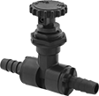
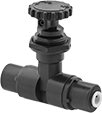
Precision Flow-Adjustment Valves with Barbed Fittings for Chemicals
- Valve Type: Needle
- For Use With: Water, Oil, Air, Argon, Butane, Carbon Dioxide, Citric Acid, Deionized Water, Diesel Fuel, Ethanol, Ethylene Glycol, Gasoline, Helium, Hydrochloric Acid, Isopropyl Alcohol, Kerosene, Krypton, Methanol, Mineral Spirits, Natural Gas, Neon, Nitric Acid, Nitrogen, Oxygen, Phosphoric Acid, Propane, Salt Water, Soap Solutions, Sodium Hydroxide, Sodium Hypochlorite, Sulfuric Acid, Toluene, Xenon, Xylene
- Seal Material: PTFE Plastic
- Packing Material: PTFE Plastic
- Needle Material: PVDF Plastic
Barbs grip onto tubing, providing a secure hold. To withstand aggressive and corrosive solutions in chemical-processing applications, these valves have a PTFE seal and a PVDF body. Turn the handle to adjust flow in small increments for metering, sampling, and other applications requiring fine flow control. Threads and a hex nut below the handle allow you to install these valves in instrument panels. They have a nut that can be tightened to compress the packing if it leaks.
![]() For technical drawings and 3-D models, click on a part number.
For technical drawings and 3-D models, click on a part number.
| For Tube ID | For Tube OD | Flow Coefficient (Cv) | Max. Pressure | Max. Temperature, °F | Panel Cutout Dia. | End-to-End Lg. | Each | |
Black PVDF Plastic Body | ||||||||
|---|---|---|---|---|---|---|---|---|
Barbed × Barbed | ||||||||
| 1/4" | 3/8" | 0.3 | 125 psi @ 140° F | 140° | 7/8" | 3 5/16" | 0000000 | 000000 |
| 3/8" | 1/2" | 0.3 | 125 psi @ 140° F | 140° | 7/8" | 3 5/16" | 0000000 | 00000 |
| 1/2" | 5/8" | 0.4 | 125 psi @ 140° F | 140° | 7/8" | 3 5/16" | 0000000 | 00000 |
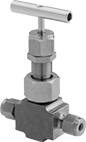
Precision Flow-Adjustment Valves with Yor-Lok Fittings for Chemicals
- Valve Type: Needle
- For Use With: Oil, Acetone, Air, Ammonia, Argon, Butane, Carbon Dioxide, Deionized Water, Diesel Fuel, Ethanol, Gasoline, Helium, Isopropyl Alcohol, Kerosene, Krypton, Methanol, Methyl Ethyl Ketone, Mineral Spirits, Natural Gas, Neon, Nitrogen, Oxygen, Propane, Soap Solutions, Sodium Hydroxide, Toluene, Xenon, Xylene
- Seal Material: PTFE Plastic
- Seat Material: 316 Stainless Steel
- Packing Material: PTFE Plastic
- Needle Material: 316 Stainless Steel
For extra gripping power and a strong seal, these valves have Yor-Lok fittings with two sleeves that bite into tubing as you tighten the nut. All are compatible with Swagelok®, Let-Lok, and Parker A-Lok fittings. The 316 stainless steel body, seal and needle, and the PTFE seat and packing can withstand aggressive and corrosive solutions in chemical-processing applications. Turn the handle to adjust flow in small increments for metering, sampling, and other applications requiring fine flow control. Threads and a hex nut below the handle allow you to mount these valves in instrument panels. All have a nut that can be tightened to compress the packing if it leaks. Valves have bubble-tight soft seats that provide a tight seal when the valve is completely closed.
Flow coefficient (Cv) is the amount of water (in gallons per minute) at 60° F that will flow through a fully open valve with a difference of 1 psi between the inlet and the outlet.
| For Tube OD | Flow Coefficient (Cv) | Max. Pressure | Temperature Range, °F | Panel Cutout Dia. | End-to-End Lg. | Each | |
316 Stainless Steel Body | |||||||
|---|---|---|---|---|---|---|---|
Yor Lok × Yor Lok | |||||||
| 1/4" | 0.56 | 7000 psi @ 400° F | -20° to 400° | 0.87" | 2 7/8" | 0000000 | 0000000 |
| 3/8" | 0.56 | 7000 psi @ 400° F | -20° to 400° | 0.87" | 2 7/8" | 0000000 | 000000 |
| 1/2" | 0.56 | 7000 psi @ 400° F | -20° to 400° | 0.87" | 3 1/8" | 0000000 | 000000 |
Precision Flow-Adjustment Valves with Push-to-Connect Fittings for Chemicals
- Valve Type: Needle
- For Use With: Water, Oil, Air, Argon, Butane, Carbon Dioxide, Citric Acid, Deionized Water, Diesel Fuel, Ethanol, Ethylene Glycol, Gasoline, Helium, Hydrochloric Acid, Isopropyl Alcohol, Kerosene, Krypton, Methanol, Mineral Spirits, Natural Gas, Neon, Nitric Acid, Nitrogen, Oxygen, Phosphoric Acid, Propane, Salt Water, Soap Solutions, Sodium Hydroxide, Sodium Hypochlorite, Sulfuric Acid, Toluene, Xenon, Xylene
- Seal Material: Fluoroelastomer Rubber
- Packing Material: PTFE Plastic
- Needle Material: PVDF Plastic
Insert tubing into the fittings on these valves—no heat, solder, or flux required. With a fluoroelastomer seal and a PVDF body, they can withstand aggressive and corrosive solutions in chemical-processing applications. Turn the handle to adjust flow in small increments for metering, sampling, and other applications requiring fine flow control. Threads and a hex nut below the handle allow you to install these valves in instrument panels. They have a nut that can be tightened to compress the packing if it leaks.