


Filter by
Fitting Connection

For Use With
Body Material
Maximum Pressure @ Temperature
Seat Material
Export Control Classification Number (ECCN)
DFARS Specialty Metals
Flanged Flow-Adjustment Valves
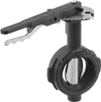
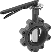
Wafer Valves with Lockable Lever Handle
 |
4 Bolt Holes |
Wafer valves must be sandwiched between two flanges; they have tabs or unthreaded holes to help align the valve between the flanges.
Lockable lever handles can be fixed in place with a padlock (not included).
Flow Coefficient (Cv)—Flow coefficient (Cv) is the amount of water (in gallons per minute) at 60° F that will flow through a fully open valve with a difference of 1 psi between the inlet and the outlet.
Pipe Size | For Max. Shackle Dia. | For Use With | Pressure Class | Flange OD | Bolt Circle Dia. | No. of Bolt Holes | Bolt Hole Size | For Bolt Dia. | Bolts Included | Flow Coefficient (Cv) | Max. Pressure @ Temp. | Temp. Range, ° F | End-to-End Lg. | Specs. Met | Valve Type | Each | |||||||||||||||||||||||||||||||||||||||||||||||||||||||||||||||||||||||||||||||||||
|---|---|---|---|---|---|---|---|---|---|---|---|---|---|---|---|---|---|---|---|---|---|---|---|---|---|---|---|---|---|---|---|---|---|---|---|---|---|---|---|---|---|---|---|---|---|---|---|---|---|---|---|---|---|---|---|---|---|---|---|---|---|---|---|---|---|---|---|---|---|---|---|---|---|---|---|---|---|---|---|---|---|---|---|---|---|---|---|---|---|---|---|---|---|---|---|---|---|---|---|
Ductile Iron Body—Painted Ductile Iron Disc | |||||||||||||||||||||||||||||||||||||||||||||||||||||||||||||||||||||||||||||||||||||||||||||||||||
| 2 | 5/16" | Air | 125, 150 | 6" | 4 3/4" | 4 | 5/8" | 5/8" | No | 115 | 200 psi @ 180° F | 10 to 180 | 1 3/4" | MSS SP-67 | Butterfly | 5158K212 | 0000000 | ||||||||||||||||||||||||||||||||||||||||||||||||||||||||||||||||||||||||||||||||||
| 2 | 5/16" | Air | 125, 150 | 6" | 4 3/4" | 4 | 5/8" | 5/8" | No | 115 | 200 psi @ 275° F | -30 to 275 | 1 3/4" | MSS SP-67 | Butterfly | 5158K112 | 000000 | ||||||||||||||||||||||||||||||||||||||||||||||||||||||||||||||||||||||||||||||||||
| 2 1/2 | 5/16" | Air | 125, 150 | 7" | 5 1/2" | 4 | 5/8" | 5/8" | No | 196 | 200 psi @ 180° F | 10 to 180 | 1 7/8" | MSS SP-67 | Butterfly | 5158K222 | 000000 | ||||||||||||||||||||||||||||||||||||||||||||||||||||||||||||||||||||||||||||||||||
| 2 1/2 | 5/16" | Air | 125, 150 | 7" | 5 1/2" | 4 | 5/8" | 5/8" | No | 196 | 200 psi @ 275° F | -30 to 275 | 1 7/8" | MSS SP-67 | Butterfly | 5158K122 | 000000 | ||||||||||||||||||||||||||||||||||||||||||||||||||||||||||||||||||||||||||||||||||
| 3 | 5/16" | Air | 125, 150 | 7 1/2" | 6" | 4 | 5/8" | 5/8" | No | 302 | 200 psi @ 180° F | 10 to 180 | 1 7/8" | MSS SP-67 | Butterfly | 5158K232 | 000000 | ||||||||||||||||||||||||||||||||||||||||||||||||||||||||||||||||||||||||||||||||||
| 3 | 5/16" | Air | 125, 150 | 7 1/2" | 6" | 4 | 5/8" | 5/8" | No | 302 | 200 psi @ 275° F | -30 to 275 | 1 7/8" | MSS SP-67 | Butterfly | 5158K132 | 000000 | ||||||||||||||||||||||||||||||||||||||||||||||||||||||||||||||||||||||||||||||||||
| 4 | 5/16" | Air | 125, 150 | 9" | 7 1/2" | 4 | 5/8" | 5/8" | No | 600 | 200 psi @ 180° F | 10 to 180 | 2 1/8" | MSS SP-67 | Butterfly | 5158K242 | 000000 | ||||||||||||||||||||||||||||||||||||||||||||||||||||||||||||||||||||||||||||||||||
| 4 | 5/16" | Air | 125, 150 | 9" | 7 1/2" | 4 | 5/8" | 5/8" | No | 600 | 200 psi @ 275° F | -30 to 275 | 2 1/8" | MSS SP-67 | Butterfly | 5158K142 | 000000 | ||||||||||||||||||||||||||||||||||||||||||||||||||||||||||||||||||||||||||||||||||
| 5 | 5/16" | Air | 125, 150 | 10" | 8 1/2" | 4 | 3/4" | 3/4" | No | 1,022 | 200 psi @ 180° F | 10 to 180 | 2 1/4" | MSS SP-67 | Butterfly | 5158K252 | 000000 | ||||||||||||||||||||||||||||||||||||||||||||||||||||||||||||||||||||||||||||||||||
| 5 | 5/16" | Air | 125, 150 | 10" | 8 1/2" | 4 | 3/4" | 3/4" | No | 1,022 | 200 psi @ 275° F | -30 to 275 | 2 1/4" | MSS SP-67 | Butterfly | 5158K152 | 000000 | ||||||||||||||||||||||||||||||||||||||||||||||||||||||||||||||||||||||||||||||||||
| 6 | 5/16" | Air | 125, 150 | 11" | 9 1/2" | 4 | 3/4" | 3/4" | No | 1,579 | 200 psi @ 180° F | 10 to 180 | 2 1/4" | MSS SP-67 | Butterfly | 5158K262 | 000000 | ||||||||||||||||||||||||||||||||||||||||||||||||||||||||||||||||||||||||||||||||||
| 6 | 5/16" | Air | 125, 150 | 11" | 9 1/2" | 4 | 3/4" | 3/4" | No | 1,579 | 200 psi @ 275° F | -30 to 275 | 2 1/4" | MSS SP-67 | Butterfly | 5158K162 | 000000 | ||||||||||||||||||||||||||||||||||||||||||||||||||||||||||||||||||||||||||||||||||
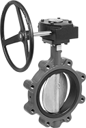
Wafer Valves with Wheel Handle
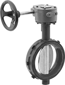 |
Wafer valves must be sandwiched between two flanges; they have tabs or unthreaded holes to help align the valve between the flanges.
Wheel handles open and close with multiple turns, providing fully adjustable flow.
Flow Coefficient (Cv)—Flow coefficient (Cv) is the amount of water (in gallons per minute) at 60° F that will flow through a fully open valve with a difference of 1 psi between the inlet and the outlet.
Pipe Size | For Use With | Pressure Class | Flange OD | Bolt Circle Dia. | No. of Bolt Holes | Bolt Hole Size | For Bolt Dia. | Bolts Included | Flow Coefficient (Cv) | Max. Pressure @ Temp. | Temp. Range, ° F | End-to-End Lg. | Specs. Met | Valve Type | Each | ||||||||||||||||||||||||||||||||||||||||||||||||||||||||||||||||||||||||||||||||||||
|---|---|---|---|---|---|---|---|---|---|---|---|---|---|---|---|---|---|---|---|---|---|---|---|---|---|---|---|---|---|---|---|---|---|---|---|---|---|---|---|---|---|---|---|---|---|---|---|---|---|---|---|---|---|---|---|---|---|---|---|---|---|---|---|---|---|---|---|---|---|---|---|---|---|---|---|---|---|---|---|---|---|---|---|---|---|---|---|---|---|---|---|---|---|---|---|---|---|---|---|
Ductile Iron Body—Painted Ductile Iron Disc | |||||||||||||||||||||||||||||||||||||||||||||||||||||||||||||||||||||||||||||||||||||||||||||||||||
| 8 | Air | 125, 150 | 13 1/2" | 11 3/4" | 4 | 3/4" | 3/4" | No | 3,136 | 200 psi @ 180° F | 10 to 180 | 2 1/2" | MSS SP-67 | Butterfly | 5158K282 | 000000000 | |||||||||||||||||||||||||||||||||||||||||||||||||||||||||||||||||||||||||||||||||||
| 8 | Air | 125, 150 | 13 1/2" | 11 3/4" | 4 | 3/4" | 3/4" | No | 3,136 | 200 psi @ 275° F | -30 to 275 | 2 1/2" | MSS SP-67 | Butterfly | 5158K182 | 00000000 | |||||||||||||||||||||||||||||||||||||||||||||||||||||||||||||||||||||||||||||||||||
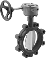
Lug Valves with Lockable Lever Handle
 | 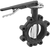 |
4 Bolt Holes | 8 Bolt Holes |
Lug valves can be sandwiched between two flanges or bolted directly to a single flange for servicing one end of the pipeline without depressurizing the other side. They have threaded flange holes with a hole pattern that matches ANSI flanges of the same pipe size.
Lockable lever handles can be fixed in place with a padlock (not included).
Flow Coefficient (Cv)—Flow coefficient (Cv) is the amount of water (in gallons per minute) at 60° F that will flow through a fully open valve with a difference of 1 psi between the inlet and the outlet.
Pipe Size | For Max. Shackle Dia. | For Use With | Pressure Class | Flange OD | Bolt Circle Dia. | No. of Bolt Holes | Bolt Hole Size | For Bolt Dia. | Bolts Included | Flow Coefficient (Cv) | Max. Pressure @ Temp. | Temp. Range, ° F | End-to-End Lg. | Specs. Met | Valve Type | Each | |||||||||||||||||||||||||||||||||||||||||||||||||||||||||||||||||||||||||||||||||||
|---|---|---|---|---|---|---|---|---|---|---|---|---|---|---|---|---|---|---|---|---|---|---|---|---|---|---|---|---|---|---|---|---|---|---|---|---|---|---|---|---|---|---|---|---|---|---|---|---|---|---|---|---|---|---|---|---|---|---|---|---|---|---|---|---|---|---|---|---|---|---|---|---|---|---|---|---|---|---|---|---|---|---|---|---|---|---|---|---|---|---|---|---|---|---|---|---|---|---|---|
Ductile Iron Body—Painted Ductile Iron Disc | |||||||||||||||||||||||||||||||||||||||||||||||||||||||||||||||||||||||||||||||||||||||||||||||||||
| 2 | 5/16" | Air | 125, 150 | 6" | 4 3/4" | 4 | 5/8" | 5/8" | No | 115 | 200 psi @ 180° F | 10 to 180 | 1 3/4" | MSS SP-67 | Butterfly | 5158K612 | 0000000 | ||||||||||||||||||||||||||||||||||||||||||||||||||||||||||||||||||||||||||||||||||
| 2 | 5/16" | Air | 125, 150 | 6" | 4 3/4" | 4 | 5/8" | 5/8" | No | 115 | 200 psi @ 275° F | -30 to 275 | 1 3/4" | MSS SP-67 | Butterfly | 5158K512 | 000000 | ||||||||||||||||||||||||||||||||||||||||||||||||||||||||||||||||||||||||||||||||||
| 2 1/2 | 5/16" | Air | 125, 150 | 7" | 5 1/2" | 4 | 5/8" | 5/8" | No | 196 | 200 psi @ 180° F | 10 to 180 | 1 7/8" | MSS SP-67 | Butterfly | 5158K622 | 000000 | ||||||||||||||||||||||||||||||||||||||||||||||||||||||||||||||||||||||||||||||||||
| 2 1/2 | 5/16" | Air | 125, 150 | 7" | 5 1/2" | 4 | 5/8" | 5/8" | No | 196 | 200 psi @ 275° F | -30 to 275 | 1 7/8" | MSS SP-67 | Butterfly | 5158K522 | 000000 | ||||||||||||||||||||||||||||||||||||||||||||||||||||||||||||||||||||||||||||||||||
| 3 | 5/16" | Air | 125, 150 | 7 1/2" | 6" | 4 | 5/8" | 5/8" | No | 302 | 200 psi @ 180° F | 10 to 180 | 1 7/8" | MSS SP-67 | Butterfly | 5158K632 | 000000 | ||||||||||||||||||||||||||||||||||||||||||||||||||||||||||||||||||||||||||||||||||
| 3 | 5/16" | Air | 125, 150 | 7 1/2" | 6" | 4 | 5/8" | 5/8" | No | 302 | 200 psi @ 275° F | -30 to 275 | 1 7/8" | MSS SP-67 | Butterfly | 5158K532 | 000000 | ||||||||||||||||||||||||||||||||||||||||||||||||||||||||||||||||||||||||||||||||||
| 4 | 5/16" | Air | 125, 150 | 9" | 7 1/2" | 8 | 5/8" | 5/8" | No | 600 | 200 psi @ 180° F | 10 to 180 | 2 1/8" | MSS SP-67 | Butterfly | 5158K642 | 000000 | ||||||||||||||||||||||||||||||||||||||||||||||||||||||||||||||||||||||||||||||||||
| 4 | 5/16" | Air | 125, 150 | 9" | 7 1/2" | 8 | 5/8" | 5/8" | No | 600 | 200 psi @ 275° F | -30 to 275 | 2 1/8" | MSS SP-67 | Butterfly | 5158K542 | 000000 | ||||||||||||||||||||||||||||||||||||||||||||||||||||||||||||||||||||||||||||||||||
| 5 | 5/16" | Air | 125, 150 | 10" | 8 1/2" | 8 | 3/4" | 3/4" | No | 1,022 | 200 psi @ 180° F | 10 to 180 | 2 1/4" | MSS SP-67 | Butterfly | 5158K652 | 000000 | ||||||||||||||||||||||||||||||||||||||||||||||||||||||||||||||||||||||||||||||||||
| 5 | 5/16" | Air | 125, 150 | 10" | 8 1/2" | 8 | 3/4" | 3/4" | No | 1,022 | 200 psi @ 275° F | -30 to 275 | 2 1/4" | MSS SP-67 | Butterfly | 5158K552 | 000000 | ||||||||||||||||||||||||||||||||||||||||||||||||||||||||||||||||||||||||||||||||||
| 6 | 5/16" | Air | 125, 150 | 11" | 9 1/2" | 8 | 3/4" | 3/4" | No | 1,579 | 200 psi @ 180° F | 10 to 180 | 2 1/4" | MSS SP-67 | Butterfly | 5158K662 | 000000 | ||||||||||||||||||||||||||||||||||||||||||||||||||||||||||||||||||||||||||||||||||
| 6 | 5/16" | Air | 125, 150 | 11" | 9 1/2" | 8 | 3/4" | 3/4" | No | 1,579 | 200 psi @ 275° F | -30 to 275 | 2 1/4" | MSS SP-67 | Butterfly | 5158K562 | 000000 | ||||||||||||||||||||||||||||||||||||||||||||||||||||||||||||||||||||||||||||||||||
Lug Valves with Wheel Handle
 |
Lug valves can be sandwiched between two flanges or bolted directly to a single flange for servicing one end of the pipeline without depressurizing the other side. They have threaded flange holes with a hole pattern that matches ANSI flanges of the same pipe size.
Wheel handles open and close with multiple turns, providing fully adjustable flow.
Flow Coefficient (Cv)—Flow coefficient (Cv) is the amount of water (in gallons per minute) at 60° F that will flow through a fully open valve with a difference of 1 psi between the inlet and the outlet.
Pipe Size | For Use With | Pressure Class | Flange OD | Bolt Circle Dia. | No. of Bolt Holes | Bolt Hole Size | For Bolt Dia. | Bolts Included | Flow Coefficient (Cv) | Max. Pressure @ Temp. | Temp. Range, ° F | End-to-End Lg. | Specs. Met | Valve Type | Each | ||||||||||||||||||||||||||||||||||||||||||||||||||||||||||||||||||||||||||||||||||||
|---|---|---|---|---|---|---|---|---|---|---|---|---|---|---|---|---|---|---|---|---|---|---|---|---|---|---|---|---|---|---|---|---|---|---|---|---|---|---|---|---|---|---|---|---|---|---|---|---|---|---|---|---|---|---|---|---|---|---|---|---|---|---|---|---|---|---|---|---|---|---|---|---|---|---|---|---|---|---|---|---|---|---|---|---|---|---|---|---|---|---|---|---|---|---|---|---|---|---|---|
Ductile Iron Body—Painted Ductile Iron Disc | |||||||||||||||||||||||||||||||||||||||||||||||||||||||||||||||||||||||||||||||||||||||||||||||||||
| 8 | Air | 125, 150 | 13 1/2" | 11 3/4" | 8 | 3/4" | 3/4" | No | 3,136 | 200 psi @ 180° F | 10 to 180 | 2 1/2" | MSS SP-67 | Butterfly | 5158K682 | 000000000 | |||||||||||||||||||||||||||||||||||||||||||||||||||||||||||||||||||||||||||||||||||
| 8 | Air | 125, 150 | 13 1/2" | 11 3/4" | 8 | 3/4" | 3/4" | No | 3,136 | 200 psi @ 275° F | -30 to 275 | 2 1/2" | MSS SP-67 | Butterfly | 5158K582 | 00000000 | |||||||||||||||||||||||||||||||||||||||||||||||||||||||||||||||||||||||||||||||||||
Precision Flow-Adjustment Valves with Yor-Lok Fittings for Chemicals
316 Stainless Steel Body
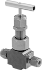 |
Flow Coefficient (Cv)—Flow coefficient (Cv) is the amount of water (in gallons per minute) at 60° F that will flow through a fully open valve with a difference of 1 psi between the inlet and the outlet.
Overall | |||||||||||||||||||||||||||||||||||||||||||||||||||||||||||||||||||||||||||||||||||||||||||||||||||
|---|---|---|---|---|---|---|---|---|---|---|---|---|---|---|---|---|---|---|---|---|---|---|---|---|---|---|---|---|---|---|---|---|---|---|---|---|---|---|---|---|---|---|---|---|---|---|---|---|---|---|---|---|---|---|---|---|---|---|---|---|---|---|---|---|---|---|---|---|---|---|---|---|---|---|---|---|---|---|---|---|---|---|---|---|---|---|---|---|---|---|---|---|---|---|---|---|---|---|---|
For Tube OD | Flow Coefficient (Cv) | Max. Pressure @ Temp. | Ht. | Lg. | Temp. Range, ° F | Seal Material | Panel Cutout Dia. | Seat Material | Packing Material | Needle Material | End-to-End Lg. | For Use With | Valve Type | Each | |||||||||||||||||||||||||||||||||||||||||||||||||||||||||||||||||||||||||||||||||||||
Yor-Lok × Yor-Lok | |||||||||||||||||||||||||||||||||||||||||||||||||||||||||||||||||||||||||||||||||||||||||||||||||||
| 1/4" | 0.56 | 7,000 psi @ 400° F | 3 5/8" | 2 7/8" | -20 to 400 | PTFE | 0.87" | 316 Stainless Steel | PTFE | 316 Stainless Steel | 2 7/8" | Oil, Acetone, Air, Ammonia, Argon, Butane, Carbon Dioxide, Deionized Water, Diesel Fuel, Ethanol, Gasoline, Helium, Isopropyl Alcohol, Kerosene, Krypton, Methanol (Methyl Alcohol), Methyl Ethyl Ketone (MEK), Mineral Spirits, Natural Gas, Neon, Nitrogen, Oxygen, Propane, Soap Solutions, Sodium Hydroxide (Caustic Soda), Toluene (Methylbenzene), Xenon, Xylene | Needle | 2563N11 | 0000000 | ||||||||||||||||||||||||||||||||||||||||||||||||||||||||||||||||||||||||||||||||||||
| 3/8" | 0.56 | 7,000 psi @ 400° F | 3 5/8" | 2 7/8" | -20 to 400 | PTFE | 0.87" | 316 Stainless Steel | PTFE | 316 Stainless Steel | 2 7/8" | Oil, Acetone, Air, Ammonia, Argon, Butane, Carbon Dioxide, Deionized Water, Diesel Fuel, Ethanol, Gasoline, Helium, Isopropyl Alcohol, Kerosene, Krypton, Methanol (Methyl Alcohol), Methyl Ethyl Ketone (MEK), Mineral Spirits, Natural Gas, Neon, Nitrogen, Oxygen, Propane, Soap Solutions, Sodium Hydroxide (Caustic Soda), Toluene (Methylbenzene), Xenon, Xylene | Needle | 2563N12 | 000000 | ||||||||||||||||||||||||||||||||||||||||||||||||||||||||||||||||||||||||||||||||||||
| 1/2" | 0.56 | 7,000 psi @ 400° F | 3 5/8" | 3 1/8" | -20 to 400 | PTFE | 0.87" | 316 Stainless Steel | PTFE | 316 Stainless Steel | 3 1/8" | Oil, Acetone, Air, Ammonia, Argon, Butane, Carbon Dioxide, Deionized Water, Diesel Fuel, Ethanol, Gasoline, Helium, Isopropyl Alcohol, Kerosene, Krypton, Methanol (Methyl Alcohol), Methyl Ethyl Ketone (MEK), Mineral Spirits, Natural Gas, Neon, Nitrogen, Oxygen, Propane, Soap Solutions, Sodium Hydroxide (Caustic Soda), Toluene (Methylbenzene), Xenon, Xylene | Needle | 2563N13 | 000000 | ||||||||||||||||||||||||||||||||||||||||||||||||||||||||||||||||||||||||||||||||||||
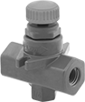
Easy-Set Plastic Threaded Precision Flow-Adjustment Valves
Black Glass-Filled Polyester Plastic Body
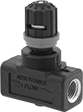 |
Flow Coefficient (Cv)—Flow coefficient (Cv) is a measurement that indicates how much airflow can pass through a valve.
Valves | Mounting Nuts | ||||||||||||||||||||||||||||||||||||||||||||||||||||||||||||||||||||||||||||||||||||||||||||||||||
|---|---|---|---|---|---|---|---|---|---|---|---|---|---|---|---|---|---|---|---|---|---|---|---|---|---|---|---|---|---|---|---|---|---|---|---|---|---|---|---|---|---|---|---|---|---|---|---|---|---|---|---|---|---|---|---|---|---|---|---|---|---|---|---|---|---|---|---|---|---|---|---|---|---|---|---|---|---|---|---|---|---|---|---|---|---|---|---|---|---|---|---|---|---|---|---|---|---|---|---|
Overall | |||||||||||||||||||||||||||||||||||||||||||||||||||||||||||||||||||||||||||||||||||||||||||||||||||
Pipe Size | Flow Coefficient (Cv) | Max. Pressure @ Temp. | Ht. | Lg. | Temp. Range, ° F | Seal Material | Panel Cutout Dia. | Seat Material | Needle Material | End-to-End Lg. | For Use With | Valve Type | Each | Each | |||||||||||||||||||||||||||||||||||||||||||||||||||||||||||||||||||||||||||||||||||||
NPTF Female × NPTF Female | |||||||||||||||||||||||||||||||||||||||||||||||||||||||||||||||||||||||||||||||||||||||||||||||||||
| 1/8 | 0.26 | 200 psi @ 200° F | 2 13/16" | 1 15/16" | 0 to 200 | Buna-N | 1" | Polypropylene | Zinc-Plated Steel | 1 15/16" | Air, Oxygen | Needle | 4891K71 | 000000 | 4891K61 | 00000 | |||||||||||||||||||||||||||||||||||||||||||||||||||||||||||||||||||||||||||||||||||
| 1/4 | 0.48 | 200 psi @ 200° F | 2 13/16" | 1 15/16" | 0 to 200 | Buna-N | 1" | Polypropylene | Zinc-Plated Steel | 1 15/16" | Air, Oxygen | Needle | 4891K72 | 00000 | 4891K61 | 0000 | |||||||||||||||||||||||||||||||||||||||||||||||||||||||||||||||||||||||||||||||||||
| 3/8 | 1.06 | 200 psi @ 200° F | 3 7/8" | 2 7/8" | 0 to 200 | Buna-N | 1 3/8" | Polypropylene | Zinc-Plated Steel | 2 7/8" | Air, Oxygen | Needle | 4891K73 | 00000 | 4891K62 | 0000 | |||||||||||||||||||||||||||||||||||||||||||||||||||||||||||||||||||||||||||||||||||
| 1/2 | 1.35 | 200 psi @ 200° F | 3 7/8" | 2 7/8" | 0 to 200 | Buna-N | 1 3/8" | Polypropylene | Zinc-Plated Steel | 2 7/8" | Air, Oxygen | Needle | 4891K74 | 00000 | 4891K62 | 0000 | |||||||||||||||||||||||||||||||||||||||||||||||||||||||||||||||||||||||||||||||||||
| 3/4 | 1.96 | 200 psi @ 200° F | 4 3/16" | 3" | 0 to 200 | Buna-N | 1 3/8" | Polypropylene | Zinc-Plated Steel | 3" | Air, Oxygen | Needle | 4891K75 | 00000 | 4891K62 | 0000 | |||||||||||||||||||||||||||||||||||||||||||||||||||||||||||||||||||||||||||||||||||
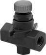
Black Glass-Filled Polyester Plastic Body with Internal Check Valve
|
Internal check valves actuate when the pressure changes to stop flow control from the controlled direction and allow free flow in the opposite direction. Valves with an internal check valve are often used to control the speed of air cylinders and air-powered motors.
Flow Coefficient (Cv)—Flow coefficient (Cv) is a measurement that indicates how much airflow can pass through a valve.
Valves | Mounting Nuts | ||||||||||||||||||||||||||||||||||||||||||||||||||||||||||||||||||||||||||||||||||||||||||||||||||
|---|---|---|---|---|---|---|---|---|---|---|---|---|---|---|---|---|---|---|---|---|---|---|---|---|---|---|---|---|---|---|---|---|---|---|---|---|---|---|---|---|---|---|---|---|---|---|---|---|---|---|---|---|---|---|---|---|---|---|---|---|---|---|---|---|---|---|---|---|---|---|---|---|---|---|---|---|---|---|---|---|---|---|---|---|---|---|---|---|---|---|---|---|---|---|---|---|---|---|---|
Overall | |||||||||||||||||||||||||||||||||||||||||||||||||||||||||||||||||||||||||||||||||||||||||||||||||||
Pipe Size | Flow Coefficient (Cv) | Max. Pressure @ Temp. | Ht. | Lg. | Temp. Range, ° F | Seal Material | Panel Cutout Dia. | Seat Material | Needle Material | End-to-End Lg. | For Use With | Valve Type | Each | Each | |||||||||||||||||||||||||||||||||||||||||||||||||||||||||||||||||||||||||||||||||||||
NPTF Female × NPTF Female | |||||||||||||||||||||||||||||||||||||||||||||||||||||||||||||||||||||||||||||||||||||||||||||||||||
| 1/8 | 0.26 | 200 psi @ 200° F | 2 13/16" | 1 15/16" | 0 to 200 | Buna-N | 1" | Polypropylene | Zinc-Plated Steel | 1 15/16" | Air, Oxygen | Needle | 48995K31 | 000000 | 4891K61 | 00000 | |||||||||||||||||||||||||||||||||||||||||||||||||||||||||||||||||||||||||||||||||||
| 1/4 | 0.48 | 200 psi @ 200° F | 2 13/16" | 1 15/16" | 0 to 200 | Buna-N | 1" | Polypropylene | Zinc-Plated Steel | 1 15/16" | Air, Oxygen | Needle | 48995K33 | 00000 | 4891K61 | 0000 | |||||||||||||||||||||||||||||||||||||||||||||||||||||||||||||||||||||||||||||||||||
| 3/8 | 1.06 | 200 psi @ 200° F | 3 7/8" | 2 7/8" | 0 to 200 | Buna-N | 1 3/8" | Polypropylene | Zinc-Plated Steel | 2 7/8" | Air, Oxygen | Needle | 48995K35 | 00000 | 4891K62 | 0000 | |||||||||||||||||||||||||||||||||||||||||||||||||||||||||||||||||||||||||||||||||||
| 1/2 | 1.35 | 200 psi @ 200° F | 3 7/8" | 2 7/8" | 0 to 200 | Buna-N | 1 3/8" | Polypropylene | Zinc-Plated Steel | 2 7/8" | Air, Oxygen | Needle | 48995K37 | 00000 | 4891K62 | 0000 | |||||||||||||||||||||||||||||||||||||||||||||||||||||||||||||||||||||||||||||||||||
| 3/4 | 1.96 | 200 psi @ 200° F | 4 3/16" | 3" | 0 to 200 | Buna-N | 1 3/8" | Polypropylene | Zinc-Plated Steel | 3" | Air, Oxygen | Needle | 48995K39 | 000000 | 4891K62 | 0000 | |||||||||||||||||||||||||||||||||||||||||||||||||||||||||||||||||||||||||||||||||||
Flanged Flow-Adjustment Valves for Chemicals
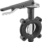
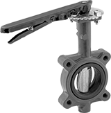
Wafer Valves with Lockable Lever Handle
 |
4 Bolt Holes |
Wafer valves must be sandwiched between two flanges; they have tabs or unthreaded holes to help align the valve between the flanges.
Lockable lever handles have 10 flow-adjustment positions. The handle can be fixed in place with a padlock (not included).
Flow Coefficient (Cv)—Flow coefficient (Cv) is the amount of water (in gallons per minute) at 60° F that will flow through a fully open valve with a difference of 1 psi between the inlet and the outlet.
Pipe Size | For Use With | For Max. Shackle Dia. | Pressure Class | Flange OD | Bolt Circle Dia. | No. of Bolt Holes | Bolt Hole Size | Bolts Included | Flow Coefficient (Cv) | Max. Pressure @ Temp. | Temp. Range, ° F | End-to-End Lg. | Valve Type | Seat Material | Specs. Met | Each | |||||||||||||||||||||||||||||||||||||||||||||||||||||||||||||||||||||||||||||||||||
|---|---|---|---|---|---|---|---|---|---|---|---|---|---|---|---|---|---|---|---|---|---|---|---|---|---|---|---|---|---|---|---|---|---|---|---|---|---|---|---|---|---|---|---|---|---|---|---|---|---|---|---|---|---|---|---|---|---|---|---|---|---|---|---|---|---|---|---|---|---|---|---|---|---|---|---|---|---|---|---|---|---|---|---|---|---|---|---|---|---|---|---|---|---|---|---|---|---|---|---|
Ductile Iron Body—Painted Ductile Iron Disc | |||||||||||||||||||||||||||||||||||||||||||||||||||||||||||||||||||||||||||||||||||||||||||||||||||
| 2 | Air, Carbon Dioxide, Diesel Fuel, Isopropyl Alcohol, Methyl Ethyl Ketone (MEK), Nitrogen, Oxygen, Toluene (Methylbenzene) | 5/16" | 125, 150 | 6" | 4 3/4" | 4 | 3/4" | No | 115 | 200 psi @ 275° F | 10 to 275 | 1 3/4" | Butterfly | Fluoroelastomer | MSS SP-67 | 46165K101 | 000000000 | ||||||||||||||||||||||||||||||||||||||||||||||||||||||||||||||||||||||||||||||||||
| 2 1/2 | Air, Carbon Dioxide, Diesel Fuel, Isopropyl Alcohol, Methyl Ethyl Ketone (MEK), Nitrogen, Oxygen, Toluene (Methylbenzene) | 5/16" | 125, 150 | 7" | 5 1/2" | 4 | 3/4" | No | 196 | 200 psi @ 275° F | 10 to 275 | 1 7/8" | Butterfly | Fluoroelastomer | MSS SP-67 | 46165K102 | 00000000 | ||||||||||||||||||||||||||||||||||||||||||||||||||||||||||||||||||||||||||||||||||
| 3 | Air, Carbon Dioxide, Diesel Fuel, Isopropyl Alcohol, Methyl Ethyl Ketone (MEK), Nitrogen, Oxygen, Toluene (Methylbenzene) | 5/16" | 125, 150 | 7 1/2" | 6" | 4 | 3/4" | No | 302 | 200 psi @ 275° F | 10 to 275 | 1 7/8" | Butterfly | Fluoroelastomer | MSS SP-67 | 46165K103 | 000000 | ||||||||||||||||||||||||||||||||||||||||||||||||||||||||||||||||||||||||||||||||||
| 4 | Air, Carbon Dioxide, Diesel Fuel, Isopropyl Alcohol, Methyl Ethyl Ketone (MEK), Nitrogen, Oxygen, Toluene (Methylbenzene) | 5/16" | 125, 150 | 9" | 7 1/2" | 4 | 3/4" | No | 600 | 200 psi @ 275° F | 10 to 275 | 2 1/8" | Butterfly | Fluoroelastomer | MSS SP-67 | 46165K104 | 00000000 | ||||||||||||||||||||||||||||||||||||||||||||||||||||||||||||||||||||||||||||||||||
| 5 | Air, Carbon Dioxide, Diesel Fuel, Isopropyl Alcohol, Methyl Ethyl Ketone (MEK), Nitrogen, Oxygen, Toluene (Methylbenzene) | 5/16" | 125, 150 | 10" | 8 1/2" | 4 | 7/8" | No | 1,022 | 200 psi @ 275° F | 10 to 275 | 2 1/4" | Butterfly | Fluoroelastomer | MSS SP-67 | 46165K105 | 00000000 | ||||||||||||||||||||||||||||||||||||||||||||||||||||||||||||||||||||||||||||||||||
| 6 | Air, Carbon Dioxide, Diesel Fuel, Isopropyl Alcohol, Methyl Ethyl Ketone (MEK), Nitrogen, Oxygen, Toluene (Methylbenzene) | 5/16" | 125, 150 | 11" | 9 1/2" | 4 | 7/8" | No | 1,579 | 200 psi @ 275° F | 10 to 275 | 2 1/4" | Butterfly | Fluoroelastomer | MSS SP-67 | 46165K106 | 00000000 | ||||||||||||||||||||||||||||||||||||||||||||||||||||||||||||||||||||||||||||||||||
Wafer Valves with Wheel Handle
|
Wafer valves must be sandwiched between two flanges; they have tabs or unthreaded holes to help align the valve between the flanges.
Wheel handles open and close with multiple turns, providing fully adjustable flow.
Flow Coefficient (Cv)—Flow coefficient (Cv) is the amount of water (in gallons per minute) at 60° F that will flow through a fully open valve with a difference of 1 psi between the inlet and the outlet.
Pipe Size | For Use With | Pressure Class | Flange OD | Bolt Circle Dia. | No. of Bolt Holes | Bolt Hole Size | Bolts Included | Flow Coefficient (Cv) | Max. Pressure @ Temp. | Temp. Range, ° F | End-to-End Lg. | Valve Type | Seat Material | Specs. Met | Each | ||||||||||||||||||||||||||||||||||||||||||||||||||||||||||||||||||||||||||||||||||||
|---|---|---|---|---|---|---|---|---|---|---|---|---|---|---|---|---|---|---|---|---|---|---|---|---|---|---|---|---|---|---|---|---|---|---|---|---|---|---|---|---|---|---|---|---|---|---|---|---|---|---|---|---|---|---|---|---|---|---|---|---|---|---|---|---|---|---|---|---|---|---|---|---|---|---|---|---|---|---|---|---|---|---|---|---|---|---|---|---|---|---|---|---|---|---|---|---|---|---|---|
Ductile Iron Body—Painted Ductile Iron Disc | |||||||||||||||||||||||||||||||||||||||||||||||||||||||||||||||||||||||||||||||||||||||||||||||||||
| 8 | Air, Carbon Dioxide, Diesel Fuel, Isopropyl Alcohol, Methyl Ethyl Ketone (MEK), Nitrogen, Oxygen, Toluene (Methylbenzene) | 125, 150 | 13 1/2" | 11 3/4" | 4 | 7/8" | No | 3,136 | 200 psi @ 275° F | 10 to 275 | 2 1/2" | Butterfly | Fluoroelastomer | MSS SP-67 | 46165K108 | 000000000 | |||||||||||||||||||||||||||||||||||||||||||||||||||||||||||||||||||||||||||||||||||
Lug Valves with Lockable Lever Handle
 |  |
4 Bolt Holes | 8 Bolt Holes |
Lug valves can be sandwiched between two flanges or bolted directly to a single flange for servicing one end of the pipeline without depressurizing the other side. They have threaded flange holes with a hole pattern that matches ANSI flanges of the same pipe size.
Lockable lever handles have 10 flow-adjustment positions. The handle can be fixed in place with a padlock (not included).
Flow Coefficient (Cv)—Flow coefficient (Cv) is the amount of water (in gallons per minute) at 60° F that will flow through a fully open valve with a difference of 1 psi between the inlet and the outlet.
Pipe Size | For Use With | For Max. Shackle Dia. | Pressure Class | Flange OD | Bolt Circle Dia. | No. of Bolt Holes | Bolt Hole Size | Bolts Included | Flow Coefficient (Cv) | Max. Pressure @ Temp. | Temp. Range, ° F | End-to-End Lg. | Valve Type | Seat Material | Specs. Met | Each | |||||||||||||||||||||||||||||||||||||||||||||||||||||||||||||||||||||||||||||||||||
|---|---|---|---|---|---|---|---|---|---|---|---|---|---|---|---|---|---|---|---|---|---|---|---|---|---|---|---|---|---|---|---|---|---|---|---|---|---|---|---|---|---|---|---|---|---|---|---|---|---|---|---|---|---|---|---|---|---|---|---|---|---|---|---|---|---|---|---|---|---|---|---|---|---|---|---|---|---|---|---|---|---|---|---|---|---|---|---|---|---|---|---|---|---|---|---|---|---|---|---|
Ductile Iron Body—Painted Ductile Iron Disc | |||||||||||||||||||||||||||||||||||||||||||||||||||||||||||||||||||||||||||||||||||||||||||||||||||
| 2 | Air, Carbon Dioxide, Diesel Fuel, Isopropyl Alcohol, Methyl Ethyl Ketone (MEK), Nitrogen, Oxygen, Toluene (Methylbenzene) | 5/16" | 125, 150 | 6" | 4 3/4" | 4 | 3/4" | No | 115 | 200 psi @ 275° F | 10 to 275 | 1 3/4" | Butterfly | Fluoroelastomer | MSS SP-67 | 46165K111 | 0000000 | ||||||||||||||||||||||||||||||||||||||||||||||||||||||||||||||||||||||||||||||||||
| 2 1/2 | Air, Carbon Dioxide, Diesel Fuel, Isopropyl Alcohol, Methyl Ethyl Ketone (MEK), Nitrogen, Oxygen, Toluene (Methylbenzene) | 5/16" | 125, 150 | 7" | 5 1/2" | 4 | 3/4" | No | 196 | 200 psi @ 275° F | 10 to 275 | 1 7/8" | Butterfly | Fluoroelastomer | MSS SP-67 | 46165K112 | 00000000 | ||||||||||||||||||||||||||||||||||||||||||||||||||||||||||||||||||||||||||||||||||
| 3 | Air, Carbon Dioxide, Diesel Fuel, Isopropyl Alcohol, Methyl Ethyl Ketone (MEK), Nitrogen, Oxygen, Toluene (Methylbenzene) | 5/16" | 125, 150 | 7 1/2" | 6" | 4 | 3/4" | No | 302 | 200 psi @ 275° F | 10 to 275 | 1 7/8" | Butterfly | Fluoroelastomer | MSS SP-67 | 46165K113 | 00000000 | ||||||||||||||||||||||||||||||||||||||||||||||||||||||||||||||||||||||||||||||||||
| 4 | Air, Carbon Dioxide, Diesel Fuel, Isopropyl Alcohol, Methyl Ethyl Ketone (MEK), Nitrogen, Oxygen, Toluene (Methylbenzene) | 5/16" | 125, 150 | 9" | 7 1/2" | 8 | 3/4" | No | 600 | 200 psi @ 275° F | 10 to 275 | 2 1/8" | Butterfly | Fluoroelastomer | MSS SP-67 | 46165K114 | 00000000 | ||||||||||||||||||||||||||||||||||||||||||||||||||||||||||||||||||||||||||||||||||
| 5 | Air, Carbon Dioxide, Diesel Fuel, Isopropyl Alcohol, Methyl Ethyl Ketone (MEK), Nitrogen, Oxygen, Toluene (Methylbenzene) | 5/16" | 125, 150 | 10" | 8 1/2" | 8 | 7/8" | No | 1,022 | 200 psi @ 275° F | 10 to 275 | 2 1/4" | Butterfly | Fluoroelastomer | MSS SP-67 | 46165K115 | 00000000 | ||||||||||||||||||||||||||||||||||||||||||||||||||||||||||||||||||||||||||||||||||
| 6 | Air, Carbon Dioxide, Diesel Fuel, Isopropyl Alcohol, Methyl Ethyl Ketone (MEK), Nitrogen, Oxygen, Toluene (Methylbenzene) | 5/16" | 125, 150 | 11" | 9 1/2" | 8 | 7/8" | No | 1,579 | 200 psi @ 275° F | 10 to 275 | 2 1/4" | Butterfly | Fluoroelastomer | MSS SP-67 | 46165K116 | 00000000 | ||||||||||||||||||||||||||||||||||||||||||||||||||||||||||||||||||||||||||||||||||
Lug Valves with Wheel Handle
 |
Lug valves can be sandwiched between two flanges or bolted directly to a single flange for servicing one end of the pipeline without depressurizing the other side. They have threaded flange holes with a hole pattern that matches ANSI flanges of the same pipe size.
Wheel handles open and close with multiple turns, providing fully adjustable flow.
Flow Coefficient (Cv)—Flow coefficient (Cv) is the amount of water (in gallons per minute) at 60° F that will flow through a fully open valve with a difference of 1 psi between the inlet and the outlet.
Pipe Size | For Use With | Pressure Class | Flange OD | Bolt Circle Dia. | No. of Bolt Holes | Bolt Hole Size | Bolts Included | Flow Coefficient (Cv) | Max. Pressure @ Temp. | Temp. Range, ° F | End-to-End Lg. | Valve Type | Seat Material | Specs. Met | Each | ||||||||||||||||||||||||||||||||||||||||||||||||||||||||||||||||||||||||||||||||||||
|---|---|---|---|---|---|---|---|---|---|---|---|---|---|---|---|---|---|---|---|---|---|---|---|---|---|---|---|---|---|---|---|---|---|---|---|---|---|---|---|---|---|---|---|---|---|---|---|---|---|---|---|---|---|---|---|---|---|---|---|---|---|---|---|---|---|---|---|---|---|---|---|---|---|---|---|---|---|---|---|---|---|---|---|---|---|---|---|---|---|---|---|---|---|---|---|---|---|---|---|
Ductile Iron Body—Painted Ductile Iron Disc | |||||||||||||||||||||||||||||||||||||||||||||||||||||||||||||||||||||||||||||||||||||||||||||||||||
| 8 | Air, Carbon Dioxide, Diesel Fuel, Isopropyl Alcohol, Methyl Ethyl Ketone (MEK), Nitrogen, Oxygen, Toluene (Methylbenzene) | 125, 150 | 13 1/2" | 11 3/4" | 8 | 7/8" | No | 3,136 | 200 psi @ 275° F | 10 to 275 | 2 1/2" | Butterfly | Fluoroelastomer | MSS SP-67 | 46165K118 | 000000000 | |||||||||||||||||||||||||||||||||||||||||||||||||||||||||||||||||||||||||||||||||||
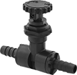
Precision Flow-Adjustment Valves with Push-to-Connect Fittings for Chemicals
PVDF Body
 |
Overall | |||||||||||||||||||||||||||||||||||||||||||||||||||||||||||||||||||||||||||||||||||||||||||||||||||
|---|---|---|---|---|---|---|---|---|---|---|---|---|---|---|---|---|---|---|---|---|---|---|---|---|---|---|---|---|---|---|---|---|---|---|---|---|---|---|---|---|---|---|---|---|---|---|---|---|---|---|---|---|---|---|---|---|---|---|---|---|---|---|---|---|---|---|---|---|---|---|---|---|---|---|---|---|---|---|---|---|---|---|---|---|---|---|---|---|---|---|---|---|---|---|---|---|---|---|---|
For Tube ID | For Tube OD | Flow Coefficient (Cv) | Max. Pressure @ Temp. | Ht. | Lg. | Seal Material | Panel Cutout Dia. | Packing Material | Needle Material | End-to-End Lg. | For Use With | Valve Type | Each | ||||||||||||||||||||||||||||||||||||||||||||||||||||||||||||||||||||||||||||||||||||||
Push to Connect × Push to Connect | |||||||||||||||||||||||||||||||||||||||||||||||||||||||||||||||||||||||||||||||||||||||||||||||||||
| 1/8" | 1/4" | 0.3 | 125 psi @ 140° F | 2 5/8" | 2 11/16" | Fluoroelastomer | 7/8" | PTFE | PVDF | 2 11/16" | Water, Oil, Air, Argon, Butane, Carbon Dioxide, Citric Acid, Deionized Water, Diesel Fuel, Ethanol, Ethylene Glycol, Gasoline, Helium, Hydrochloric Acid, Isopropyl Alcohol, Kerosene, Krypton, Methanol (Methyl Alcohol), Mineral Spirits, Natural Gas, Neon, Nitric Acid, Nitrogen, Oxygen, Phosphoric Acid, Propane, Salt Water, Soap Solutions, Sodium Hydroxide (Caustic Soda), Sodium Hypochlorite (Bleach), Sulfuric Acid, Toluene (Methylbenzene), Xenon, Xylene | Needle | 3112N11 | 000000 | |||||||||||||||||||||||||||||||||||||||||||||||||||||||||||||||||||||||||||||||||||||
| 1/4" | 3/8" | 0.4 | 125 psi @ 140° F | 2 5/8" | 2 11/16" | Fluoroelastomer | 7/8" | PTFE | PVDF | 2 11/16" | Water, Oil, Air, Argon, Butane, Carbon Dioxide, Citric Acid, Deionized Water, Diesel Fuel, Ethanol, Ethylene Glycol, Gasoline, Helium, Hydrochloric Acid, Isopropyl Alcohol, Kerosene, Krypton, Methanol (Methyl Alcohol), Mineral Spirits, Natural Gas, Neon, Nitric Acid, Nitrogen, Oxygen, Phosphoric Acid, Propane, Salt Water, Soap Solutions, Sodium Hydroxide (Caustic Soda), Sodium Hypochlorite (Bleach), Sulfuric Acid, Toluene (Methylbenzene), Xenon, Xylene | Needle | 3112N12 | 00000 | |||||||||||||||||||||||||||||||||||||||||||||||||||||||||||||||||||||||||||||||||||||
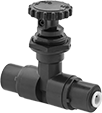
Precision Flow-Adjustment Valves with Barbed Fittings for Chemicals
 |
Barbs grip onto tubing, providing a secure hold. To withstand aggressive and corrosive solutions in chemical-processing applications, these valves have a PTFE seal and a PVDF body. Turn the handle to adjust flow in small increments for metering, sampling, and other applications requiring fine flow control. Threads and a hex nut below the handle allow you to install these valves in instrument panels. They have a nut that can be tightened to compress the packing if it leaks.
For Tube ID | For Tube OD | Flow Coefficient (Cv) | Max. Pressure @ Temp. | Max. Temp., ° F | Panel Cutout Dia. | End-to-End Lg. | Valve Type | For Use With | Seal Material | Packing Material | Needle Material | Each | |||||||||||||||||||||||||||||||||||||||||||||||||||||||||||||||||||||||||||||||||||||||
|---|---|---|---|---|---|---|---|---|---|---|---|---|---|---|---|---|---|---|---|---|---|---|---|---|---|---|---|---|---|---|---|---|---|---|---|---|---|---|---|---|---|---|---|---|---|---|---|---|---|---|---|---|---|---|---|---|---|---|---|---|---|---|---|---|---|---|---|---|---|---|---|---|---|---|---|---|---|---|---|---|---|---|---|---|---|---|---|---|---|---|---|---|---|---|---|---|---|---|---|
Black PVDF Body | |||||||||||||||||||||||||||||||||||||||||||||||||||||||||||||||||||||||||||||||||||||||||||||||||||
Barbed × Barbed | |||||||||||||||||||||||||||||||||||||||||||||||||||||||||||||||||||||||||||||||||||||||||||||||||||
| 1/4" | 3/8" | 0.3 | 125 psi @ 140° F | 140 | 7/8" | 3 5/16" | Needle | Water, Oil, Air, Argon, Butane, Carbon Dioxide, Citric Acid, Deionized Water, Diesel Fuel, Ethanol, Ethylene Glycol, Gasoline, Helium, Hydrochloric Acid, Isopropyl Alcohol, Kerosene, Krypton, Methanol (Methyl Alcohol), Mineral Spirits, Natural Gas, Neon, Nitric Acid, Nitrogen, Oxygen, Phosphoric Acid, Propane, Salt Water, Soap Solutions, Sodium Hydroxide (Caustic Soda), Sodium Hypochlorite (Bleach), Sulfuric Acid, Toluene (Methylbenzene), Xenon, Xylene | PTFE | PTFE | PVDF | 3010N11 | 000000 | ||||||||||||||||||||||||||||||||||||||||||||||||||||||||||||||||||||||||||||||||||||||
| 3/8" | 1/2" | 0.3 | 125 psi @ 140° F | 140 | 7/8" | 3 5/16" | Needle | Water, Oil, Air, Argon, Butane, Carbon Dioxide, Citric Acid, Deionized Water, Diesel Fuel, Ethanol, Ethylene Glycol, Gasoline, Helium, Hydrochloric Acid, Isopropyl Alcohol, Kerosene, Krypton, Methanol (Methyl Alcohol), Mineral Spirits, Natural Gas, Neon, Nitric Acid, Nitrogen, Oxygen, Phosphoric Acid, Propane, Salt Water, Soap Solutions, Sodium Hydroxide (Caustic Soda), Sodium Hypochlorite (Bleach), Sulfuric Acid, Toluene (Methylbenzene), Xenon, Xylene | PTFE | PTFE | PVDF | 3010N12 | 00000 | ||||||||||||||||||||||||||||||||||||||||||||||||||||||||||||||||||||||||||||||||||||||
| 1/2" | 5/8" | 0.4 | 125 psi @ 140° F | 140 | 7/8" | 3 5/16" | Needle | Water, Oil, Air, Argon, Butane, Carbon Dioxide, Citric Acid, Deionized Water, Diesel Fuel, Ethanol, Ethylene Glycol, Gasoline, Helium, Hydrochloric Acid, Isopropyl Alcohol, Kerosene, Krypton, Methanol (Methyl Alcohol), Mineral Spirits, Natural Gas, Neon, Nitric Acid, Nitrogen, Oxygen, Phosphoric Acid, Propane, Salt Water, Soap Solutions, Sodium Hydroxide (Caustic Soda), Sodium Hypochlorite (Bleach), Sulfuric Acid, Toluene (Methylbenzene), Xenon, Xylene | PTFE | PTFE | PVDF | 3010N13 | 00000 | ||||||||||||||||||||||||||||||||||||||||||||||||||||||||||||||||||||||||||||||||||||||
Threaded Precision Flow-Adjustment Valves for Chemicals
Dark Gray PVC Body
 |
Flow Coefficient (Cv)—Flow coefficient (Cv) is the amount of water (in gallons per minute) at 60° F that will flow through a fully open valve with a difference of 1 psi between the inlet and the outlet.
Overall | |||||||||||||||||||||||||||||||||||||||||||||||||||||||||||||||||||||||||||||||||||||||||||||||||||
|---|---|---|---|---|---|---|---|---|---|---|---|---|---|---|---|---|---|---|---|---|---|---|---|---|---|---|---|---|---|---|---|---|---|---|---|---|---|---|---|---|---|---|---|---|---|---|---|---|---|---|---|---|---|---|---|---|---|---|---|---|---|---|---|---|---|---|---|---|---|---|---|---|---|---|---|---|---|---|---|---|---|---|---|---|---|---|---|---|---|---|---|---|---|---|---|---|---|---|---|
Pipe Size | Flow Coefficient (Cv) | Max. Pressure @ Temp. | Ht. | Lg. | Temp. Range, ° F | Seal Material | Panel Cutout Dia. | Seat Material | Needle Material | End-to-End Lg. | For Use With | Valve Type | Each | ||||||||||||||||||||||||||||||||||||||||||||||||||||||||||||||||||||||||||||||||||||||
NPT Female × NPT Female | |||||||||||||||||||||||||||||||||||||||||||||||||||||||||||||||||||||||||||||||||||||||||||||||||||
| 1/4 | 0.64 | 150 psi @ 70° F | 3 7/16" | 2 1/2" | 40 to 150 | Fluoroelastomer | 1 5/16" | PTFE | PVC | 2 1/2" | Water, Citric Acid, Diesel Fuel, Ethylene Glycol, Hydrochloric Acid, Isopropyl Alcohol, Kerosene, Nitric Acid, Phosphoric Acid, Salt Water, Soap Solutions | Needle | 4981K11 | 0000000 | |||||||||||||||||||||||||||||||||||||||||||||||||||||||||||||||||||||||||||||||||||||
| 3/8 | 0.72 | 150 psi @ 70° F | 3 7/16" | 2 1/2" | 40 to 150 | Fluoroelastomer | 1 5/16" | PTFE | PVC | 2 1/2" | Water, Citric Acid, Diesel Fuel, Ethylene Glycol, Hydrochloric Acid, Isopropyl Alcohol, Kerosene, Nitric Acid, Phosphoric Acid, Salt Water, Soap Solutions | Needle | 4981K12 | 000000 | |||||||||||||||||||||||||||||||||||||||||||||||||||||||||||||||||||||||||||||||||||||
| 1/2 | 0.79 | 150 psi @ 70° F | 3 7/16" | 2 1/2" | 40 to 150 | Fluoroelastomer | 1 5/16" | PTFE | PVC | 2 1/2" | Water, Citric Acid, Diesel Fuel, Ethylene Glycol, Hydrochloric Acid, Isopropyl Alcohol, Kerosene, Nitric Acid, Phosphoric Acid, Salt Water, Soap Solutions | Needle | 4981K13 | 000000 | |||||||||||||||||||||||||||||||||||||||||||||||||||||||||||||||||||||||||||||||||||||
Black Polypropylene Body
 |
Flow Coefficient (Cv)—Flow coefficient (Cv) is the amount of water (in gallons per minute) at 60° F that will flow through a fully open valve with a difference of 1 psi between the inlet and the outlet.
Overall | |||||||||||||||||||||||||||||||||||||||||||||||||||||||||||||||||||||||||||||||||||||||||||||||||||
|---|---|---|---|---|---|---|---|---|---|---|---|---|---|---|---|---|---|---|---|---|---|---|---|---|---|---|---|---|---|---|---|---|---|---|---|---|---|---|---|---|---|---|---|---|---|---|---|---|---|---|---|---|---|---|---|---|---|---|---|---|---|---|---|---|---|---|---|---|---|---|---|---|---|---|---|---|---|---|---|---|---|---|---|---|---|---|---|---|---|---|---|---|---|---|---|---|---|---|---|
Pipe Size | Flow Coefficient (Cv) | Max. Pressure @ Temp. | Ht. | Lg. | Temp. Range, ° F | Seal Material | Panel Cutout Dia. | Seat Material | Needle Material | End-to-End Lg. | For Use With | Valve Type | Each | ||||||||||||||||||||||||||||||||||||||||||||||||||||||||||||||||||||||||||||||||||||||
NPT Female × NPT Female | |||||||||||||||||||||||||||||||||||||||||||||||||||||||||||||||||||||||||||||||||||||||||||||||||||
| 1/4 | 0.64 | 150 psi @ 70° F | 3 7/16" | 2 1/2" | 40 to 260 | Fluoroelastomer | 1 5/16" | PTFE | Polypropylene | 2 1/2" | Water, Citric Acid, Ethylene Glycol, Hydrochloric Acid, Isopropyl Alcohol, Kerosene, Nitric Acid, Salt Water, Soap Solutions | Needle | 4803K25 | 0000000 | |||||||||||||||||||||||||||||||||||||||||||||||||||||||||||||||||||||||||||||||||||||
| 3/8 | 0.72 | 150 psi @ 70° F | 3 7/16" | 2 1/2" | 40 to 260 | Fluoroelastomer | 1 5/16" | PTFE | Polypropylene | 2 1/2" | Water, Citric Acid, Ethylene Glycol, Hydrochloric Acid, Isopropyl Alcohol, Kerosene, Nitric Acid, Salt Water, Soap Solutions | Needle | 4803K26 | 000000 | |||||||||||||||||||||||||||||||||||||||||||||||||||||||||||||||||||||||||||||||||||||
| 1/2 | 0.79 | 150 psi @ 70° F | 3 7/16" | 2 1/2" | 40 to 260 | Fluoroelastomer | 1 5/16" | PTFE | Polypropylene | 2 1/2" | Water, Citric Acid, Ethylene Glycol, Hydrochloric Acid, Isopropyl Alcohol, Kerosene, Nitric Acid, Salt Water, Soap Solutions | Needle | 4803K27 | 000000 | |||||||||||||||||||||||||||||||||||||||||||||||||||||||||||||||||||||||||||||||||||||
