


Maximum Pull Maximum Pull |
|---|
DFARS (Defense Acquisition Regulations Supplement) DFARS (Defense AcquisitionRegulations Supplement) |
|---|
Wire Connection Type Wire Connection Type |
|---|
|
REACH (Registration, Evaluation, Authorization and Restriction of Chemicals) REACH (Registration,Evaluation, Authorization and Restriction of Chemicals) |
|---|
|
RoHS (Restriction of Hazardous Substances) RoHS (Restriction ofHazardous Substances) |
|---|
|
Maximum Gripping Capacity Maximum Gripping Capacity |
|---|
Gripper Application Gripper Application |
|---|
|
About Magnets
More
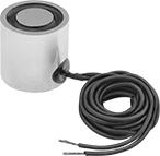
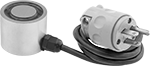
DC-Powered Electromagnets
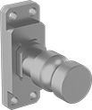
Position the face of these magnets in direct contact with a flat metal surface and turn on the power to create a magnetic hold. Magnets have wire leads that connect to a DC electromagnet power supply (sold separately). Holding power is not adjustable. When turned off, the magnet will still have some residual magnetism.
Magnets with spring-loaded release have a pin that pops up to separate the object and magnet when the power is turned off.
Warning: Maximum pull ratings are based on direct contact with rust-free and unpainted iron plate. Variations in material condition will significantly reduce these ratings. Do not use for lifting over people.
![]() For technical drawings and 3-D models, click on a part number.
For technical drawings and 3-D models, click on a part number.
| Wattage, W | OD | Ht. | Max. Pull, lbs. | Sets of Poles | Max. Temperature, °F | Number of Mounting Holes | Wire Lead Lg. | Features | Each | |
12V DC | ||||||||||
|---|---|---|---|---|---|---|---|---|---|---|
| 1.4 | 1/2" | 1 1/2" | 4 | 1 | 100° | 1 | 24" | __ | 000000 | 000000 |
| 1.4 | 3/4" | 1 1/4" | 9 | 1 | 100° | 1 | 24" | __ | 00000000 | 00000 |
| 1.4 | 1" | 3/4" | 26 | 1 | 100° | 1 | 24" | __ | 00000000 | 00000 |
| 3.6 | 1" | 1 1/4" | 32 | 1 | 100° | 1 | 24" | __ | 00000000 | 00000 |
| 4.4 | 1 1/4" | 1 1/4" | 50 | 1 | 100° | 1 | 24" | __ | 00000000 | 00000 |
| 4.6 | 1 1/2" | 1 1/2" | 80 | 1 | 100° | 1 | 24" | __ | 00000000 | 00000 |
| 5.6 | 2" | 1 5/8" | 180 | 1 | 100° | 1 | 24" | __ | 00000000 | 00000 |
24V DC | ||||||||||
| 0.9 | 25/32" | 63/64" | 1 | 1 | 100° | 1 | 8" | Spring-Loaded Release | 0000000 | 000000 |
| 1.4 | 1/2" | 1 1/2" | 4 | 1 | 100° | 1 | 24" | __ | 0000000 | 00000 |
| 1.4 | 3/4" | 1 1/4" | 9 | 1 | 100° | 1 | 24" | __ | 00000000 | 00000 |
| 1.4 | 1" | 3/4" | 26 | 1 | 100° | 1 | 24" | __ | 00000000 | 00000 |
| 2 | 1.18" | 63/64" | 6 | 1 | 100° | 1 | 8" | Spring-Loaded Release | 0000000 | 000000 |
| 2.9 | 1.57" | 63/64" | 22 | 1 | 100° | 1 | 8" | Spring-Loaded Release | 0000000 | 000000 |
| 3.6 | 1" | 1 1/4" | 32 | 1 | 100° | 1 | 24" | __ | 00000000 | 00000 |
| 4.4 | 1 1/4" | 1 1/4" | 50 | 1 | 100° | 1 | 24" | __ | 00000000 | 00000 |
| 4.6 | 1 1/2" | 1 1/2" | 80 | 1 | 100° | 1 | 24" | __ | 00000000 | 00000 |
| 5.6 | 2" | 1 5/8" | 180 | 1 | 100° | 1 | 24" | __ | 00000000 | 00000 |
110V DC | ||||||||||
| 8 | 3 1/2" | 1 1/2" | 650 | 1 | 100° | 2 | 24" | __ | 0000000 | 000000 |
| 33 | 4" | 3" | 1,000 | 1 | 100° | 2 | 24" | __ | 0000000 | 000000 |
| 60 | 10" | 2 1/2" | 4,700 | 1 | 100° | 2 | 72" | __ | 0000000 | 000000 |
| Wattage, W | Wd. | Lg. | Ht. | Max. Pull, lbs. | Sets of Poles | Max. Temperature, °F | Number of Mounting Holes | Wire Lead Lg. | Each | |
12V DC | ||||||||||
|---|---|---|---|---|---|---|---|---|---|---|
| 8 | 1 1/2" | 1 1/2" | 1 1/4" | 100 | 1 | 100° | 1 | 24" | 00000000 | 0000000 |
| 10 | 1 1/2" | 2 1/2" | 1 1/4" | 160 | 1 | 100° | 2 | 24" | 00000000 | 000000 |
| 14 | 2 1/2" | 2 1/2" | 1 1/2" | 300 | 1 | 100° | 1 | 36" | 00000000 | 000000 |
| 29 | 2 1/2" | 4 1/2" | 1 7/8" | 600 | 1 | 100° | 2 | 36" | 00000000 | 000000 |
24V DC | ||||||||||
| 8 | 1 1/2" | 1 1/2" | 1 1/4" | 100 | 1 | 100° | 1 | 24" | 00000000 | 000000 |
| 10 | 1 1/2" | 2 1/2" | 1 1/4" | 160 | 1 | 100° | 2 | 24" | 00000000 | 000000 |
| 14 | 2 1/2" | 2 1/2" | 1 1/2" | 300 | 1 | 100° | 1 | 36" | 00000000 | 000000 |
| 28 | 3 1/2" | 3 1/2" | 2" | 700 | 1 | 100° | 1 | 36" | 00000000 | 000000 |
| 29 | 2 1/2" | 4 1/2" | 1 7/8" | 600 | 1 | 100° | 2 | 36" | 00000000 | 000000 |
110V DC | ||||||||||
| 12 | 2 1/2" | 4 1/2" | 2" | 750 | 1 | 100° | 2 | 24" | 0000000 | 000000 |
| 37 | 3" | 6" | 2" | 1,000 | 1 | 100° | 2 | 24" | 0000000 | 000000 |
| 58 | 4" | 8" | 2 1/2" | 1,700 | 1 | 100° | 2 | 36" | 00000000 | 000000 |
| 65 | 6" | 12" | 3 1/2" | 5,000 | 1 | 100° | 2 | 72" | 0000000 | 000000 |
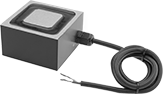
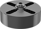
DC-Powered Electromagnets with Parallel Poles
Parallel poles create a better magnetic hold on thinly painted, plated, or coated flat metal surfaces than other magnets. A terminal block on the magnet connects to a DC electromagnet power supply (sold separately). Holding power is not adjustable. When turned off, the magnet will still have some residual magnetism.
Warning: Maximum pull ratings are based on direct contact with rust-free and unpainted iron plate. Variations in material condition will significantly reduce these ratings. Do not use for lifting over people.
![]() For technical drawings and 3-D models, click on a part number.
For technical drawings and 3-D models, click on a part number.
| Wattage, W | Wd. | Lg. | Ht. | Max. Pull, lbs. | Sets of Poles | Max. Temperature, °F | Thread Size | Thread Dp. | Number of Mounting Holes | Mounting Hole Center-to-Center | Electrical Connection Type | Each | |
24V DC | |||||||||||||
|---|---|---|---|---|---|---|---|---|---|---|---|---|---|
| 4 | 1" | 1" | 1 3/8" | 20 | 1 | 100° | 10-32 | 1/4" | 2 | 1/2" | Hardwire | 0000000 | 0000000 |
| 6 | 1" | 2" | 1 3/8" | 80 | 1 | 100° | 1/4"-20 | 1/4" | 2 | 1" | Hardwire | 0000000 | 000000 |
| 11 | 1" | 3" | 1 3/8" | 170 | 1 | 100° | 1/4"-20 | 1/4" | 2 | 2" | Hardwire | 0000000 | 000000 |
| 13 | 1" | 4" | 1 3/8" | 210 | 1 | 100° | 1/4"-20 | 1/4" | 2 | 3" | Hardwire | 0000000 | 000000 |
| 22 | 1" | 6" | 1 3/8" | 260 | 1 | 100° | 1/4"-20 | 1/4" | 2 | 4 1/2" | Hardwire | 0000000 | 000000 |
| 22 | 2" | 4" | 2 3/4" | 470 | 1 | 100° | 5/16"-18 | 1/4" | 2 | 3" | Hardwire | 0000000 | 000000 |
| 38 | 2" | 6" | 2 3/4" | 620 | 1 | 100° | 5/16"-18 | 1/4" | 2 | 4 1/2" | Hardwire | 0000000 | 000000 |
| 52 | 2" | 8" | 2 3/4" | 930 | 1 | 100° | 5/16"-18 | 1/4" | 2 | 6 1/2" | Hardwire | 0000000 | 000000 |
Plug-In Electromagnets
Position the face of these magnets in direct contact with a flat metal surface and plug in to create a magnetic hold. The plug contains a transformer that converts power from AC to DC, so no additional wiring or power source is needed. Holding power is not adjustable. When turned off, the magnet will still have some residual magnetism.
Warning: Maximum pull ratings are based on direct contact with rust-free and unpainted iron plate. Variations in material condition will significantly reduce these ratings. Do not use for lifting over people.
![]() For technical drawings and 3-D models, click on a part number.
For technical drawings and 3-D models, click on a part number.
| Wattage, W | OD | Ht. | Max. Pull, lbs. | Sets of Poles | Max. Temperature, °F | Thread Size | Thread Dp. | Number of Mounting Holes | Cord Lg., ft. | Each | |
120V AC | |||||||||||
|---|---|---|---|---|---|---|---|---|---|---|---|
| 2.8 | 1 1/4" | 1 1/4" | 40 | 1 | 100° | 1/4"-20 | 3/8" | 1 | 3 | 0000000 | 0000000 |
| 3.6 | 1 3/4" | 1 5/8" | 110 | 1 | 100° | 1/4"-20 | 1/2" | 1 | 3 | 0000000 | 000000 |
| 8 | 2" | 1 5/8" | 90 | 1 | 100° | 1/4"-20 | 1/2" | 1 | 3 | 0000000 | 000000 |
| 14 | 2" | 2 1/2" | 100 | 1 | 100° | 1/4"-20 | 1/2" | 1 | 3 | 0000000 | 000000 |
| 25 | 3" | 3" | 200 | 1 | 100° | 5/16"-18 | 1/2" | 1 | 3 | 0000000 | 000000 |
| Wattage, W | Wd. | Lg. | Ht. | Max. Pull, lbs. | Sets of Poles | Max. Temperature, °F | Thread Size | Thread Dp. | Number of Mounting Holes | Center-to-Center | Cord Lg., ft. | Each | |
120V AC | |||||||||||||
|---|---|---|---|---|---|---|---|---|---|---|---|---|---|
| 8 | 2 1/2" | 2 1/2" | 1 1/2" | 280 | 1 | 100° | 1/4"-20 | 1/2" | 2 | 3/4" | 3 | 0000000 | 0000000 |
| 10 | 1 1/2" | 2 1/2" | 1 1/4" | 80 | 1 | 100° | 10-32 | 1/2" | 2 | 1" | 3 | 0000000 | 000000 |
| 30 | 2 1/2" | 4 1/2" | 1 7/8" | 300 | 1 | 100° | 1/4"-20 | 1/2" | 2 | 2" | 3 | 0000000 | 000000 |
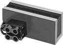
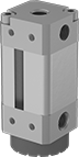
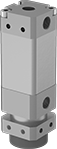
Air-Powered Magnetic Grippers
Connect these magnetic grippers to an air system to lift odd-shaped and perforated metal parts that often cause traditional vacuum cups to lose hold. Designed to work in any position, they only require one flat surface to securely grip parts. All have durable rare earth magnets that stay engaged, so they won’t drop parts in the event of air loss. Plus, unlike electromagnetic grippers, they do not need electric power to create a magnetic hold. Use these grippers in a variety of automated production lines and robotic pick-and-place systems.
Standard and heavy-load grippers have two air connections, one at each end, and a magnetic piston. One connection uses air to extend the piston and grip your part, while the other uses air to retract the piston and release the magnetic hold. All of these grippers have top and side mounting threads for attaching an optional mounting adapter that fits in tool arms commonly found in automation applications. Standard grippers with a stainless steel gripping surface withstand scrapes from parts with rough edges better than those with an aluminum gripping surface. Those with a proximity sensor signal when the magnetic piston is gripping or releasing a part, and uses that information to trigger other actions in your system. The sensors have a standard 4-pole micro M12 plug for electrical connections. Use heavy-load grippers for high temperatures when working near furnaces or near welding jobs.
Low-clearance grippers have one air connection that supplies a burst of air to release the magnetic hold. Those for destacking have a shallow magnetic field, so you can use them to lift and separate a top sheet from a stack of metal sheets.
Grippers with PNP sensors communicate proximity with a positive signal, while those with NPN sensors send a negative signal.
CE-marked grippers meet stringent European Union safety standards.
Friction rings absorb impact as grippers take hold to protect your parts from damage.
Note: Capacities listed are based on lifting flat metal that has a clean, smooth surface. If used on dirty, oily, thin, or curved surfaces, the capacities will be reduced.
Warning: Never use to lift people or items over people.
![]() For technical drawings and 3-D models, click on a part number.
For technical drawings and 3-D models, click on a part number.
Grippers | ||||||||||||||||||
|---|---|---|---|---|---|---|---|---|---|---|---|---|---|---|---|---|---|---|
O'all | Port | Temp., °F | Top Mount. Location | Side Mount. Location | Replacement Friction Rings | |||||||||||||
| Max. Gripping Cap. | Lg., mm | Wd., mm | Dp., mm | Pressure Range, psi | Pipe Size | Thread Type | Min. | Max. | Plug Type | Pipe Size | Thread Type | Thread Size | Thread Type | Specifications Met | Each | Each | ||
Aluminum Housing with Aluminum Gripping Surface | ||||||||||||||||||
With Friction Ring | ||||||||||||||||||
| 2.6 lbs. / 1.1 kg | 70 | 30 | 30 | 55-85 | 1/8 | BSPP | 45° | 155° | __ | 1/8 | BSPP | M4 × 0.7 mm | Metric | CE Marked | 0000000 | 0000000 | 0000000 | 000000 |
| 7.4 lbs. / 3.3 kg | 70 | 40 | 40 | 55-85 | 1/8 | BSPP | 45° | 155° | __ | 1/4 | BSPP | M4 × 0.7 mm | Metric | CE Marked | 0000000 | 000000 | 0000000 | 00000 |
| 13.4 lbs. / 6.1 kg | 80 | 50 | 50 | 55-85 | 1/8 | BSPP | 45° | 155° | __ | 1/4 | BSPP | M5 × 0.8 mm | Metric | CE Marked | 0000000 | 000000 | 0000000 | 00000 |
| 21.7 lbs. / 9.8 kg | 80 | 70 | 70 | 55-85 | 1/8 | BSPP | 45° | 155° | __ | 1/4 | BSPP | M5 × 0.8 mm | Metric | CE Marked | 0000000 | 000000 | 0000000 | 00000 |
With Friction Ring and PNP Proximity Sensor | ||||||||||||||||||
| 2.6 lbs. / 1.1 kg | 70 | 30 | 30 | 55-85 | 1/8 | BSPP | 45° | 155° | 4-Pole Micro M12 | 1/8 | BSPP | M4 × 0.7 mm | Metric | CE Marked | 0000000 | 000000 | 0000000 | 00000 |
| 7.4 lbs. / 3.3 kg | 70 | 40 | 40 | 55-85 | 1/8 | BSPP | 45° | 155° | 4-Pole Micro M12 | 1/4 | BSPP | M4 × 0.7 mm | Metric | CE Marked | 0000000 | 000000 | 0000000 | 00000 |
| 13.4 lbs. / 6.1 kg | 80 | 50 | 50 | 55-85 | 1/8 | BSPP | 45° | 155° | 4-Pole Micro M12 | 1/4 | BSPP | M5 × 0.8 mm | Metric | CE Marked | 0000000 | 000000 | 0000000 | 00000 |
| 21.7 lbs. / 9.8 kg | 80 | 70 | 70 | 55-85 | 1/8 | BSPP | 45° | 155° | 4-Pole Micro M12 | 1/4 | BSPP | M5 × 0.8 mm | Metric | CE Marked | 0000000 | 000000 | 0000000 | 00000 |
With Friction Ring and NPN Proximity Sensor | ||||||||||||||||||
| 2.6 lbs. / 1.1 kg | 70 | 30 | 30 | 55-85 | 1/8 | BSPP | 45° | 155° | 4-Pole Micro M12 | 1/8 | BSPP | M4 × 0.7 mm | Metric | CE Marked | 0000000 | 000000 | 0000000 | 00000 |
| 7.4 lbs. / 3.3 kg | 70 | 40 | 40 | 55-85 | 1/8 | BSPP | 45° | 155° | 4-Pole Micro M12 | 1/4 | BSPP | M4 × 0.7 mm | Metric | CE Marked | 0000000 | 000000 | 0000000 | 00000 |
| 13.4 lbs. / 6.1 kg | 80 | 50 | 50 | 55-85 | 1/8 | BSPP | 45° | 155° | 4-Pole Micro M12 | 1/4 | BSPP | M5 × 0.8 mm | Metric | CE Marked | 0000000 | 000000 | 0000000 | 00000 |
| 21.7 lbs. / 9.8 kg | 80 | 70 | 70 | 55-85 | 1/8 | BSPP | 45° | 155° | 4-Pole Micro M12 | 1/4 | BSPP | M5 × 0.8 mm | Metric | CE Marked | 0000000 | 000000 | 0000000 | 00000 |
Aluminum Housing with Stainless Steel Gripping Surface | ||||||||||||||||||
With Friction Ring | ||||||||||||||||||
| 2.6 lbs. / 1.1 kg | 61 | 30 | 30 | 55-85 | 1/8 | BSPP | 45° | 155° | __ | 1/8 | BSPP | M4 × 0.7 mm | Metric | CE Marked | 0000000 | 000000 | 0000000 | 00000 |
| 7.4 lbs. / 3.3 kg | 61 | 40 | 40 | 55-85 | 1/8 | BSPP | 45° | 155° | __ | 1/4 | BSPP | M4 × 0.7 mm | Metric | CE Marked | 0000000 | 000000 | 0000000 | 00000 |
| 13.4 lbs. / 6.1 kg | 71 | 50 | 50 | 55-85 | 1/8 | BSPP | 45° | 155° | __ | 1/4 | BSPP | M5 × 0.8 mm | Metric | CE Marked | 0000000 | 000000 | 0000000 | 00000 |
| 21.7 lbs. / 9.8 kg | 71 | 70 | 70 | 55-85 | 1/8 | BSPP | 45° | 155° | __ | 1/4 | BSPP | M5 × 0.8 mm | Metric | CE Marked | 0000000 | 000000 | 0000000 | 00000 |
Grippers | ||||||||||||||||||
|---|---|---|---|---|---|---|---|---|---|---|---|---|---|---|---|---|---|---|
O'all | Port | Temp., °F | Top Mount. Location | Side Mount. Location | Replacement Friction Rings | |||||||||||||
| Max. Gripping Cap. | Lg., mm | Wd., mm | Dp., mm | Pressure Range, psi | Pipe Size | Thread Size | Thread Type | Min. | Max. | Pipe Size | Thread Type | Thread Size | Thread Type | Specifications Met | Each | Each | ||
Aluminum Housing with Aluminum Gripping Surface | ||||||||||||||||||
With Friction Ring | ||||||||||||||||||
| 1.1 lbs. / 0.5 kg | 78 | 20 | 20 | 40-85 | __ | M5 × 0.8 mm | Metric | 45° | 155° | 1/8 | BSPP | M3 × 0.5 mm | Metric | CE Marked | 0000000 | 0000000 | 0000000 | 000000 |
| 6.7 lbs. / 3 kg | 99 | 30 | 30 | 40-85 | 1/8 | __ | BSPP | 45° | 155° | 1/8 | BSPP | M4 × 0.7 mm | Metric | CE Marked | 0000000 | 000000 | 0000000 | 00000 |
| 15.7 lbs. / 7.1 kg | 99 | 40 | 40 | 40-85 | 1/8 | __ | BSPP | 45° | 155° | 1/4 | BSPP | M4 × 0.7 mm | Metric | CE Marked | 0000000 | 000000 | 0000000 | 00000 |
| 21.7 lbs. / 9.8 kg | 123 | 50 | 50 | 40-85 | 1/8 | __ | BSPP | 45° | 155° | 1/4 | BSPP | M5 × 0.8 mm | Metric | CE Marked | 0000000 | 000000 | 0000000 | 00000 |
Gripper (Shown with
Optional Friction Ring)
Grippers | |||||||||||||||||
|---|---|---|---|---|---|---|---|---|---|---|---|---|---|---|---|---|---|
O'all | Port | Temp., °F | Top Mount. Location | Side Mount. Location | Optional Friction Rings | ||||||||||||
| Max. Gripping Cap. | Lg., mm | Wd., mm | Dp., mm | Pressure Range, psi | Pipe Size | Thread Type | Min. | Max. | Pipe Size | Thread Type | Thread Size | Thread Type | Specifications Met | Each | Each | ||
Aluminum Housing with Steel Gripping Surface | |||||||||||||||||
| 8.9 lbs. / 4 kg | 99 | 30 | 30 | 40-85 | 1/8 | BSPP | 45° | 300° | 1/8 | BSPP | M4 × 0.7 mm | Metric | CE Marked | 0000000 | 0000000 | 0000000 | 000000 |
| 19.4 lbs. / 8.8 kg | 99 | 40 | 40 | 40-85 | 1/8 | BSPP | 45° | 300° | 1/4 | BSPP | M4 × 0.7 mm | Metric | CE Marked | 0000000 | 000000 | 0000000 | 00000 |
| 27.7 lbs. / 12.5 kg | 123 | 50 | 50 | 40-85 | 1/8 | BSPP | 45° | 300° | 1/4 | BSPP | M5 × 0.8 mm | Metric | CE Marked | 0000000 | 000000 | 0000000 | 00000 |
Clearance/Destacking
Gripper
Port | |||||||||
|---|---|---|---|---|---|---|---|---|---|
| Max. Gripping Cap. | OD, mm | O'all Lg., mm | For Min. Destacking Thick. | Pressure Range, psi | Pipe Size | Thread Type | Max. Temp., °F | Each | |
Aluminum Housing with Aluminum Gripping Surface | |||||||||
| 2.83 lbs. / 1.2 kg | 38 | 63.5 | __ | 25-60 | 3/8 | NPT | 140° | 000000 | 0000000 |
| 10 lbs. / 4.5 kg | 76 | 63.5 | __ | 25-60 | 3/8 | NPT | 140° | 000000 | 000000 |
Aluminum Housing with Aluminum Gripping Surface—For Destacking | |||||||||
| 8 lbs. / 3.6 kg | 76 | 63.5 | 0.03" | 25-60 | 3/8 | NPT | 140° | 000000 | 000000 |
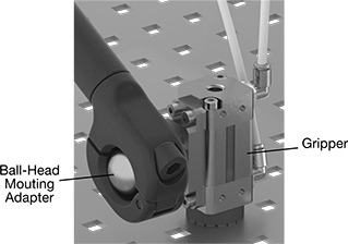
Use mounting adapters for attaching grippers to tool positioning arms. Those for two grippers have more holding strength for heavier parts. They’re also good for handling longer parts.
| For Gripper Width, mm | For Number of Grippers | Bolt Diameter, mm | Ball Diameter, mm | Wt. | Material | Mounting Fasteners Included | Each | |
For Standard Grippers | ||||||||
|---|---|---|---|---|---|---|---|---|
Ball-Head Mounting Adapter | ||||||||
| 30, 40 | 1 | __ | 28.5 | 0.17 lbs./ 0.08 kg | Aluminum | Yes | 0000000 | 000000 |
| 30, 40 | 2 | __ | 28.5 | 0.25 lbs./ 0.12 kg | Aluminum | Yes | 0000000 | 000000 |
| 50, 70 | 1 | __ | 28.5 | 0.23 lbs./ 0.1 kg | Aluminum | Yes | 0000000 | 000000 |
| 50, 70 | 2 | __ | 28.5 | 0.39 lbs./ 0.18 kg | Aluminum | Yes | 0000000 | 000000 |
Bolt-Head Mounting Adapter | ||||||||
| 30, 40 | 1 | 19 | __ | 0.14 lbs./ 0.06 kg | Aluminum | Yes | 0000000 | 00000 |
| 30, 40 | 2 | 19 | __ | 0.23 lbs./ 0.1 kg | Aluminum | Yes | 0000000 | 000000 |
| 50, 70 | 1 | 19 | __ | 0.18 lbs./ 0.09 kg | Aluminum | Yes | 0000000 | 000000 |
| 50, 70 | 2 | 19 | __ | 0.36 lbs./ 0.16 kg | Aluminum | Yes | 0000000 | 000000 |
For Heavy-Load Grippers and Heavy-Load Grippers for High Temperatures | ||||||||
Ball-Head Mounting Adapter | ||||||||
| 20 | 1 | __ | 28.5 | 0.31 lbs./ 0.14 kg | Aluminum | Yes | 0000000 | 00000 |
| 30, 40 | 1 | __ | 28.5 | 0.39 lbs./ 0.18 kg | Aluminum | Yes | 0000000 | 00000 |
| 50 | 1 | __ | 28.5 | 0.47 lbs./ 0.21 kg | Aluminum | Yes | 0000000 | 00000 |
Bolt-Head Mounting Adapter | ||||||||
| 20 | 1 | 19 | __ | 0.23 lbs./ 0.1 kg | Aluminum | Yes | 0000000 | 00000 |
| 30, 40 | 1 | 19 | __ | 0.31 lbs./ 0.14 kg | Aluminum | Yes | 0000000 | 00000 |
| 50 | 1 | 19 | __ | 0.37 lbs./ 0.17 kg | Aluminum | Yes | 0000000 | 00000 |
Use robot tool mounts with threaded connections to mount grippers to robot arms with ISO 31.5, 40, 50, or 63 mounting patterns. If you don't see your robot model number listed, measure the bolt circle diameter to determine mounting compatibility.
Robot Tool | End of Robot Arm (Bolt On) | |||||||||
|---|---|---|---|---|---|---|---|---|---|---|
| Pipe Size | Gender | Mounting Fasteners Included | Bolt Circle Dia. (Mounting Hole Pattern Compatibility) | Mounting Fasteners Included | Max. Load Cap. | Includes | For Robot Arm Manufacturer (Series/Model Number) | Each | ||
Threaded | ||||||||||
| For Grippers with 1/8 BSPP Top Mount | 3/8 | Female | Yes | 31.5 mm (ISO 31.5) 40 mm (ISO 40) 50 mm (ISO 50) 63 mm (ISO 63) | Yes | 110 lbs. / 50 kg | Universal 1/8 Male Thread Adapter | ABB (IRB 360 6/1600, 8/1130; IRB 120; IRB 140; IRB 1200; IRB 1410; IRB 1520ID; IRB 1600; IRB 2400; IRB 2600) FANUC (CR 4iA, 7iA; CRX 10iA, 10iA/L; LR Mate 200iD/7L; M-20 iA) KUKA Robotics (KR 10 R1100-2) Omron (TM 5, 12, 14) Precise Automation (PAVP6; PF3400; PP100) Productive Robotics (OB7) Staubli (TX2 90) Universal Robots (UR3; UR3e; UR5; UR5e; UR10; UR10e; UR16; UR16e) Yaskawa/Motoman (GP 7, 8; MH 3BM, 3F, 5LS II, 5S II; MPP 3H, 3S; HC 10T; SIA 10D, 10F) | 00000000 | 0000000 |
| For Grippers with 1/4 BSPP Top Mount | 3/8 | Female | Yes | 31.5 mm (ISO 31.5) 40 mm (ISO 40) 50 mm (ISO 50) 63 mm (ISO 63) | Yes | 110 lbs. / 50 kg | Universal 1/4 Male Thread Adapter | ABB (IRB 360 6/1600, 8/1130; IRB 120; IRB 140; IRB 1200; IRB 1410; IRB 1520ID; IRB 1600; IRB 2400; IRB 2600) FANUC (CR 4iA, 7iA; CRX 10iA, 10iA/L; LR Mate 200iD/7L; M-20 iA) KUKA Robotics (KR 10 R1100-2) Omron (TM 5, 12, 14) Precise Automation (PAVP6; PF3400; PP100) Productive Robotics (OB7) Staubli (TX2 90) Universal Robots (UR3; UR3e; UR5; UR5e; UR10; UR10e; UR16; UR16e) Yaskawa/Motoman (GP 7, 8; MH 3BM, 3F, 5LS II, 5S II; MPP 3H, 3S; HC 10T; SIA 10D, 10F) | 00000000 | 000000 |
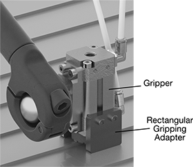

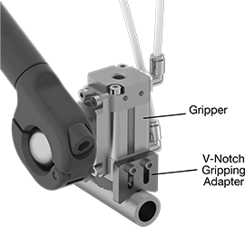
Add V-notch gripping adapters to grippers when you need a better hold on round parts, such as bars and tubes. Use rectangular gripping adapters with grippers for grasping uneven or curved parts that don’t have one flat surface that’s large enough to secure a hold—they’re designed to contact two separate flat surfaces.
| For Gripper Width, mm | For Workpiece Diameter, mm | Wt. | Material | Mounting Fasteners Included | Pair | |
For Heavy-Load Grippers and Heavy-Load Grippers for High Temperatures | ||||||
|---|---|---|---|---|---|---|
V-Notch Gripping Adapter | ||||||
| 20 | 3-10 | 0.03 lbs./0.01 kg | Aluminum | Yes | 0000000 | 000000 |
| 30, 40 | 10-20 | 0.09 lbs./0.04 kg | Aluminum | Yes | 0000000 | 00000 |
| 50 | 20-30 | 0.11 lbs./0.05 kg | Aluminum | Yes | 0000000 | 00000 |
Rectangular Gripping Adapter | ||||||
| 20 | __ | 0.03 lbs./0.02 kg | Aluminum | Yes | 0000000 | 00000 |
| 30, 40 | __ | 0.09 lbs./0.04 kg | Aluminum | Yes | 0000000 | 00000 |
| 50 | __ | 0.14 lbs./0.06 kg | Aluminum | Yes | 0000000 | 00000 |
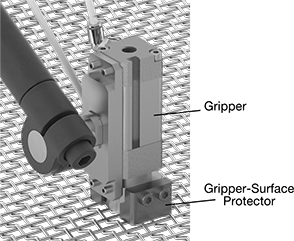
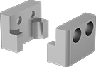
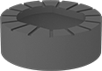
Gripper-surface protectors guard gripper surfaces from damage. Use them when handling hard or rough parts, such as metal sheets in hot-forming processes. If your gripper has friction rings, they are usually removed when using these protectors.