


Filter by
Electrical Connector Component

Housing Connection Method
Military Specification
Electrical Connection
Maximum Temperature
Housing Finish
Wire Connection
Housing Thread Size
DFARS Specialty Metals
Export Control Classification Number (ECCN)
Mil. Spec. Push-In Connectors
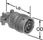
Solder Plugs—External Housing Lock
 | |
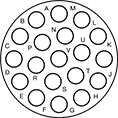
19 Poles |
No. of Poles | Voltage | Current, amp | For Wire Ga. | For Cable OD | Lg. | Wd. | Ht. | Housing Material | Temp. Range, ° F | Connector Shell Size | Mil. Spec. | Each | ||
|---|---|---|---|---|---|---|---|---|---|---|---|---|---|---|
| 19 | 600V AC/850V DC | 7.5 | 24, 23, 22, 21, 20 | 0.38" to 0.55" | 1.9" | 1.1" | 1.1" | Cadmium-Plated Aluminum | -65 to 255 | 14 | MIL-DTL-26482, MS3111F14-19P | 6134T66 | 000000 |
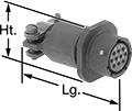
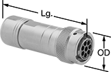
Solder Plugs—Internal Housing Lock
 | |
19 Poles |
No. of Poles | Voltage | Current, amp | For Wire Ga. | For Cable OD | OD | Lg. | Housing Material | Temp. Range, ° F | Connector Shell Size | Mil. Spec. | Each | ||
|---|---|---|---|---|---|---|---|---|---|---|---|---|---|
| 19 | 600V AC/850V DC | 7.5 | 24, 23, 22, 21, 20 | 0.38" to 0.55" | 1.2" | 1.9" | Cadmium-Plated Aluminum | -65 to 255 | 14 | MIL-DTL-26482, MS3116F14-19P | 6134T46 | 000000 |
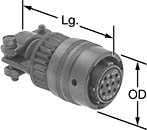
Solder Sockets—External Housing Lock
 | |
19 Poles |
No. of Poles | Voltage | Current, amp | For Wire Ga. | For Cable OD | Lg. | Wd. | Ht. | Housing Material | Temp. Range, ° F | Connector Shell Size | Mil. Spec. | Each | ||
|---|---|---|---|---|---|---|---|---|---|---|---|---|---|---|
| 19 | 600V AC/850V DC | 7.5 | 24, 23, 22, 21, 20 | 0.38" to 0.55" | 1.9" | 1.1" | 1.1" | Cadmium-Plated Aluminum | -65 to 255 | 14 | MIL-DTL-26482, MS3111F14-19S | 6134T76 | 000000 |
Solder Sockets—Internal Housing Lock
 | |
19 Poles |
No. of Poles | Voltage | Current, amp | For Wire Ga. | For Cable OD | OD | Lg. | Housing Material | Temp. Range, ° F | Connector Shell Size | Mil. Spec. | Each | ||
|---|---|---|---|---|---|---|---|---|---|---|---|---|---|
| 19 | 600V AC/850V DC | 7.5 | 24, 23, 22, 21, 20 | 0.38" to 0.55" | 1.2" | 1.9" | Cadmium-Plated Aluminum | -65 to 255 | 14 | MIL-DTL-26482, MS3116F14-19S | 6134T56 | 000000 |
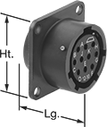
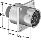
Male Panel-Mount Solder Receptacles—External Housing Lock
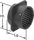 | |
19 Poles |
No. of Poles | Voltage | Current, amp | For Wire Ga. | Lg. | Wd. | Ht. | Housing Material | For Panel Cutout Dia. | Temp. Range, ° F | Connector Shell Size | Mil. Spec. | Each | ||
|---|---|---|---|---|---|---|---|---|---|---|---|---|---|---|
| 19 | 600V AC/850V DC | 7.5 | 24, 23, 22, 21, 20 | 0.8" | 1.1" | 1.1" | Cadmium-Plated Aluminum | 0.82" | -65 to 255 | 14 | MIL-DTL-26482, MS3112E14-19P | 6134T26 | 000000 |
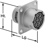
Female Panel-Mount Solder Receptacles—External Housing Lock
 | |
19 Poles |
No. of Poles | Voltage | Current, amp | For Wire Ga. | Lg. | Wd. | Ht. | Housing Material | For Panel Cutout Dia. | Temp. Range, ° F | Connector Shell Size | Mil. Spec. | Each | ||
|---|---|---|---|---|---|---|---|---|---|---|---|---|---|---|
| 19 | 600V AC/850V DC | 7.5 | 24, 23, 22, 21, 20 | 0.8" | 1.1" | 1.1" | Cadmium-Plated Aluminum | 0.99" | -65 to 255 | 14 | MIL-DTL-26482, MS3112E14-19S | 6134T36 | 000000 |
M23 Connectors
For Control
 |  |  |  |
Plug | Socket | Male Receptacles | Male Receptacles with Mounting Holes |
Plugs, Sockets, and Receptacles | Caps | Replacement Housings | Replacement Inserts | |||||||||||||||
|---|---|---|---|---|---|---|---|---|---|---|---|---|---|---|---|---|---|---|
Low Current | High Current | |||||||||||||||||
No. of Poles | Pole Layout | Voltage | No. of Poles | Current, amp | No. of Poles | Current, amp | Wire Connection Method | Enclosure Rating | Each | Each | Each | Each | ||||||
Plugs | ||||||||||||||||||
| 19 | Clockwise | 100V AC/100V DC | 16 | 8 | 3 | 10 | Solder | IP67, IP69K, NEMA 4X | 1807T26 | 000000 | 1807T62 | 00000 | 1807T92 | 000000 | 1807T87 | 000000 | ||
Sockets | ||||||||||||||||||
| 19 | Counterclockwise | 100V AC/100V DC | 16 | 8 | 3 | 10 | Solder | IP67, IP69K, NEMA 4X | 1807T17 | 00000 | 1807T61 | 00000 | 1807T91 | 00000 | 1807T86 | 00000 | ||
Male Receptacles | ||||||||||||||||||
| 19 | Clockwise | 100V AC/100V DC | 16 | 8 | 3 | 10 | Solder | IP67, IP69K, NEMA 4X | 1807T46 | 00000 | 1807T62 | 0000 | 1807T94 | 00000 | 1807T87 | 00000 | ||
Male Receptacles with Mounting Holes | ||||||||||||||||||
| 19 | Clockwise | 100V AC/100V DC | 16 | 8 | 3 | 10 | Solder | IP67, IP69K, NEMA 4X | 1807T36 | 00000 | 1807T62 | 0000 | 1807T93 | 00000 | 1807T87 | 00000 | ||
Mil. Spec. Compatible Connectors
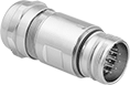
Crimp-On Plugs—Internal Housing Lock
 |  |
19 Poles (Clockwise) |
Mil. Spec. Plugs | Crimpers | ||||||||||||||
|---|---|---|---|---|---|---|---|---|---|---|---|---|---|---|---|
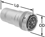
No. of Poles | Pole Layout | Voltage | Current, amp | For Wire Ga. | For Cable OD | OD | Lg. | Housing Material | Temp. Range, ° F | Connector Shell Size | Each | Each | |||
| 19 | Clockwise | 250V AC/250V DC | 7.5 | 30, 29, 28, 27, 26, 25, 24, 23, 22, 21, 20 | 0.24" to 0.39" | 1.2" | 2.9" | Nickel-Plated Zinc Alloy | -40 to 220 | 14 | 6168T13 | 000000 | 6168T3 | 000000000 | |
| 19 | Clockwise | 250V AC/500V AC/250V DC/500V DC | 13 | 26, 25, 24, 23, 22, 21, 20, 19, 18 | 0.35" to 0.57" | 1.3" | 3.1" | Nickel-Plated Zinc Alloy | -40 to 220 | 16 | 6168T21 | 00000 | 6168T3 | 00000000 | |
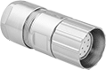
Crimp-On Sockets—Internal Housing Lock
 |  |
19 Poles (Counterclockwise) |
Mil. Spec. Sockets | Crimpers | ||||||||||||||
|---|---|---|---|---|---|---|---|---|---|---|---|---|---|---|---|
No. of Poles | Pole Layout | Voltage | Current, amp | For Wire Ga. | For Cable OD | OD | Lg. | Housing Material | Temp. Range, ° F | Connector Shell Size | Each | Each | |||
| 19 | Counterclockwise | 250V AC/250V DC | 7.5 | 30, 29, 28, 27, 26, 25, 24, 23, 22, 21, 20 | 0.24" to 0.39" | 1.2" | 2.9" | Nickel-Plated Zinc Alloy | -40 to 220 | 14 | 6168T43 | 000000 | 6168T3 | 000000000 | |
| 19 | Counterclockwise | 250V AC/500V AC/250V DC/500V DC | 13 | 26, 25, 24, 23, 22, 21, 20, 19, 18 | 0.39" to 0.55" | 1.3" | 3.1" | Nickel-Plated Zinc Alloy | -40 to 220 | 16 | 6168T41 | 00000 | 6168T3 | 00000000 | |
Male Panel-Mount Crimp-On Receptacles—External Housing Lock
 | |
19 Poles (Clockwise) |
Crimpers—Crimpers are required for wire installation.
Mil. Spec. Receptacles | Crimpers | |||||||||||||||
|---|---|---|---|---|---|---|---|---|---|---|---|---|---|---|---|---|
No. of Poles | Pole Layout | Voltage | Current, amp | For Wire Ga. | Lg. | Wd. | Ht. | Housing Material | For Panel Cutout Dia. | Temp. Range, ° F | Connector Shell Size | Each | Each | |||
| 19 | Clockwise | 250V AC/250V DC | 7.5 | 30, 29, 28, 27, 26, 25, 24, 23, 22, 21, 20 | 1.3" | 1.1" | 1.1" | Nickel-Plated Zinc Alloy | 0.91" | -40 to 220 | 14 | 6168T53 | 000000 | 6168T3 | 000000000 | |
| 19 | Clockwise | 250V AC/500V AC/250V DC/500V DC | 13 | 26, 25, 24, 23, 22, 21, 20, 19, 18 | 1.3" | 1.2" | 1.2" | Nickel-Plated Zinc Alloy | 1" | -40 to 220 | 16 | 6168T62 | 00000 | 6168T3 | 00000000 | |
Female Panel-Mount Crimp-On Receptacles—External Housing Lock
 | |
19 Poles (Counterclockwise) |
Mil. Spec. Receptacles | Crimpers | |||||||||||||||
|---|---|---|---|---|---|---|---|---|---|---|---|---|---|---|---|---|
No. of Poles | Pole Layout | Voltage | Current, amp | For Wire Ga. | Lg. | Wd. | Ht. | Housing Material | For Panel Cutout Dia. | Temp. Range, ° F | Connector Shell Size | Each | Each | |||
| 19 | Counterclockwise | 250V AC/250V DC | 7.5 | 30, 29, 28, 27, 26, 25, 24, 23, 22, 21, 20 | 1.3" | 1.1" | 1.1" | Nickel-Plated Zinc Alloy | 0.91" | -40 to 220 | 14 | 6168T73 | 000000 | 6168T3 | 000000000 | |
| 19 | Counterclockwise | 250V AC/500V AC/250V DC/500V DC | 13 | 26, 25, 24, 23, 22, 21, 20, 19, 18 | 1" | 1.2" | 1.2" | Nickel-Plated Zinc Alloy | 1" | -40 to 220 | 16 | 6168T81 | 00000 | 6168T3 | 00000000 | |
