Half-Groove Dowel Pins
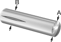
These pins make good hinges or pivots. The grooves pinch shut when pressed into a hole, creating tension and holding the pin in place. The grooved half locks pins in position, while the smooth half acts as a pivot. For the best fit, the hole should be equal to or slightly larger than the diameter shown. The ends are chamfered for easy insertion. Pins are made of zinc-plated steel for good strength and some corrosion resistance. Breaking strength is measured as double shear, which is the force required to break a pin into three pieces. Also known as type H pins.
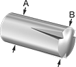
Tapered pins are good when part of the assembly must be a free fit.
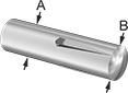
Reverse-tapered pins are useful when the ungrooved portion will act as a stop or handle.
For technical drawings and 3-D models, click on a part number.
Lg. | Dia. (A) | Dia. (A) Tolerance | Dia. (B) | Dia. (B) Tolerance | Groove Lg. | Breaking Strength, lbs. | Specifications Met | Pkg. Qty. | Pkg. | |
Dowel Pins—Zinc-Plated12L14 Carbon Steel | ||||||||||
---|---|---|---|---|---|---|---|---|---|---|
3/32" Dia. | ||||||||||
1/4" | 0.094" | -0.002" to 0" | 0.101" | -0.003" to 0.003" | 1/8" | 850 | __ | 25 | 000000000 | 000000 |
1/2" | 0.094" | -0.002" to 0" | 0.101" | -0.003" to 0.003" | 1/4" | 850 | __ | 25 | 000000000 | 00000 |
1/8" Dia. | ||||||||||
1/2" | 0.125" | -0.002" to 0" | 0.134" | -0.003" to 0.003" | 1/4" | 1,600 | __ | 25 | 000000000 | 00000 |
3/4" | 0.125" | -0.002" to 0" | 0.134" | -0.003" to 0.003" | 3/8" | 1,600 | __ | 25 | 000000000 | 00000 |
1" | 0.125" | -0.002" to 0" | 0.133" | -0.003" to 0.003" | 1/2" | 1,600 | __ | 25 | 000000000 | 00000 |
5/32" Dia. | ||||||||||
1/2" | 0.156" | -0.002" to 0" | 0.166" | -0.003" to 0.003" | 1/4" | 2,300 | __ | 25 | 000000000 | 00000 |
3/4" | 0.156" | -0.002" to 0" | 0.166" | -0.003" to 0.003" | 3/8" | 2,300 | __ | 25 | 000000000 | 00000 |
1" | 0.156" | -0.002" to 0" | 0.165" | -0.003" to 0.003" | 1/2" | 2,300 | __ | 25 | 000000000 | 00000 |
3/16" Dia. | ||||||||||
1/2" | 0.188" | -0.002" to 0" | 0.198" | -0.003" to 0.003" | 1/4" | 3,300 | __ | 25 | 000000000 | 00000 |
3/4" | 0.188" | -0.002" to 0" | 0.198" | -0.003" to 0.003" | 3/8" | 3,300 | __ | 25 | 000000000 | 00000 |
1" | 0.188" | -0.002" to 0" | 0.198" | -0.003" to 0.003" | 1/2" | 3,300 | __ | 10 | 000000000 | 0000 |
1 1/2" | 0.188" | -0.002" to 0" | 0.197" | -0.003" to 0.003" | 3/4" | 3,300 | __ | 10 | 000000000 | 00000 |
1/4" Dia. | ||||||||||
3/4" | 0.25" | -0.002" to 0" | 0.263" | -0.003" to 0.003" | 3/8" | 5,800 | __ | 25 | 000000000 | 00000 |
1" | 0.25" | -0.002" to 0" | 0.263" | -0.003" to 0.003" | 1/2" | 5,800 | __ | 25 | 000000000 | 00000 |
1 1/4" | 0.25" | -0.002" to 0" | 0.263" | -0.003" to 0.003" | 5/8" | 5,800 | __ | 10 | 000000000 | 0000 |
1 1/2" | 0.25" | -0.002" to 0" | 0.262" | -0.003" to 0.003" | 3/4" | 5,800 | __ | 10 | 000000000 | 00000 |
5/16" Dia. | ||||||||||
3/4" | 0.313" | -0.002" to 0" | 0.329" | -0.003" to 0.003" | 3/8" | 7,600 | __ | 10 | 000000000 | 0000 |
1" | 0.313" | -0.002" to 0" | 0.329" | -0.003" to 0.003" | 1/2" | 7,600 | __ | 10 | 000000000 | 0000 |
1 1/4" | 0.313" | -0.002" to 0" | 0.329" | -0.003" to 0.003" | 5/8" | 7,600 | __ | 10 | 000000000 | 0000 |
3/8" Dia. | ||||||||||
1" | 0.375" | -0.002" to 0" | 0.394" | -0.003" to 0.003" | 1/2" | 11,000 | __ | 10 | 000000000 | 00000 |
Dowel Pins with Tapered Groove—Zinc-Plated12L13 Carbon Steel | ||||||||||
2mm Dia. | ||||||||||
10mm | 2mm | -0.025mm to 0mm | 2.2mm | 0mm to 0.05mm | 5mm | 600 | ISO 8745 | 10 | 000000000 | 0000 |
14mm | 2mm | -0.025mm to 0mm | 2.2mm | 0mm to 0.05mm | 7mm | 600 | ISO 8745 | 10 | 000000000 | 0000 |
2.5mm Dia. | ||||||||||
6mm | 2.5mm | -0.025mm to 0mm | 2.7mm | -0.05mm to 0.05mm | 3mm | 950 | ISO 8745 | 10 | 000000000 | 0000 |
10mm | 2.5mm | -0.025mm to 0mm | 2.7mm | -0.05mm to 0.05mm | 5mm | 950 | ISO 8745 | 10 | 000000000 | 0000 |
3mm Dia. | ||||||||||
6mm | 3mm | -0.025mm to 0mm | 3.2mm | -0.05mm to 0.05mm | 3mm | 1,400 | ISO 8745 | 10 | 000000000 | 0000 |
8mm | 3mm | -0.025mm to 0mm | 3.2mm | -0.05mm to 0.05mm | 4mm | 1,400 | ISO 8745 | 10 | 000000000 | 0000 |
12mm | 3mm | -0.025mm to 0mm | 3.3mm | -0.05mm to 0.05mm | 6mm | 1,400 | ISO 8745 | 10 | 000000000 | 0000 |
20mm | 3mm | -0.025mm to 0mm | 3.3mm | -0.05mm to 0.05mm | 10mm | 1,400 | ISO 8745 | 10 | 000000000 | 0000 |
24mm | 3mm | -0.025mm to 0mm | 3.3mm | -0.05mm to 0.05mm | 12mm | 1,400 | ISO 8745 | 10 | 000000000 | 0000 |
26mm | 3mm | -0.025mm to 0mm | 3.3mm | -0.05mm to 0.05mm | 13mm | 1,400 | ISO 8745 | 10 | 000000000 | 0000 |
4mm Dia. | ||||||||||
10mm | 4mm | -0.075mm to 0mm | 4.3mm | -0.05mm to 0.05mm | 5mm | 2,500 | ISO 8745 | 10 | 000000000 | 0000 |
5mm Dia. | ||||||||||
16mm | 5mm | -0.075mm to 0mm | 5.3mm | -0.05mm to 0.05mm | 8mm | 3,900 | ISO 8745 | 10 | 000000000 | 0000 |
18mm | 5mm | -0.075mm to 0mm | 5.3mm | -0.05mm to 0.05mm | 9mm | 3,900 | ISO 8745 | 10 | 000000000 | 00000 |
30mm | 5mm | -0.075mm to 0mm | 5.4mm | -0.05mm to 0.05mm | 15mm | 3,900 | ISO 8745 | 10 | 000000000 | 00000 |
6mm Dia. | ||||||||||
12mm | 6mm | -0.075mm to 0mm | 6.3mm | -0.05mm to 0.05mm | 6mm | 5,700 | ISO 8745 | 10 | 000000000 | 00000 |
20mm | 6mm | -0.075mm to 0mm | 6.3mm | -0.05mm to 0.05mm | 10mm | 5,700 | ISO 8745 | 10 | 000000000 | 00000 |
26mm | 6mm | -0.075mm to 0mm | 6.4mm | -0.05mm to 0.05mm | 13mm | 5,700 | ISO 8745 | 10 | 000000000 | 00000 |
30mm | 6mm | -0.075mm to 0mm | 6.4mm | -0.05mm to 0.05mm | 15mm | 5,700 | ISO 8745 | 10 | 000000000 | 00000 |
40mm | 6mm | -0.075mm to 0mm | 6.4mm | -0.05mm to 0.05mm | 20mm | 5,700 | ISO 8745 | 10 | 000000000 | 00000 |
8mm Dia. | ||||||||||
16mm | 8mm | -0.09mm to 0mm | 8.3mm | -0.05mm to 0.05mm | 8mm | 10,100 | ISO 8745 | 5 | 000000000 | 00000 |
Dowel Pins with Reverse-Tapered Groove—Zinc-Plated12L13 Carbon Steel | ||||||||||
2mm Dia. | ||||||||||
8mm | 2mm | -0.025mm to 0mm | 2.1mm | 0mm to 0.05mm | 4mm | 600 | ISO 8741 | 10 | 000000000 | 0000 |
2.5mm Dia. | ||||||||||
14mm | 2.5mm | -0.025mm to 0mm | 2.7mm | -0.05mm to 0.05mm | 7mm | 950 | ISO 8741 | 10 | 000000000 | 0000 |
3mm Dia. | ||||||||||
12mm | 3mm | -0.025mm to 0mm | 3.1mm | -0.05mm to 0.05mm | 6mm | 1,400 | ISO 8741 | 10 | 000000000 | 0000 |
14mm | 3mm | -0.025mm to 0mm | 3.2mm | -0.05mm to 0.05mm | 7mm | 1,400 | ISO 8741 | 10 | 000000000 | 0000 |
4mm Dia. | ||||||||||
10mm | 4mm | -0.075mm to 0mm | 4.2mm | -0.05mm to 0.05mm | 5mm | 1,400 | ISO 8741 | 10 | 000000000 | 0000 |
16mm | 4mm | -0.075mm to 0mm | 4.2mm | -0.05mm to 0.05mm | 8mm | 2,500 | ISO 8741 | 10 | 000000000 | 0000 |
20mm | 4mm | -0.075mm to 0mm | 4.2mm | -0.05mm to 0.05mm | 10mm | 2,500 | ISO 8741 | 10 | 000000000 | 0000 |
30mm | 4mm | -0.075mm to 0mm | 4.3mm | -0.05mm to 0.05mm | 15mm | 2,500 | ISO 8741 | 10 | 000000000 | 0000 |
5mm Dia. | ||||||||||
30mm | 5mm | -0.075mm to 0mm | 5.3mm | -0.05mm to 0.05mm | 15mm | 3,900 | ISO 8741 | 10 | 000000000 | 00000 |
6mm Dia. | ||||||||||
14mm | 6mm | -0.075mm to 0mm | 6.2mm | -0.05mm to 0.05mm | 7mm | 5,700 | ISO 8741 | 10 | 000000000 | 00000 |
16mm | 6mm | -0.075mm to 0mm | 6.2mm | -0.05mm to 0.05mm | 8mm | 5,700 | ISO 8741 | 10 | 000000000 | 00000 |
Half-Groove Dowel Pins with Notch
These pins are commonly used as anchors for tension springs. The grooved half locks pins in position, and spring ends fit in to the notch. The grooves pinch shut when pressed into a hole, creating tension and holding the pin in place. For the best fit, the hole should be equal to or slightly larger than the diameter shown. The ends are rounded for easy insertion. Pins are made of zinc-plated steel for good strength and some corrosion resistance. Breaking strength is measured as double shear, which is the force required to break a pin into three pieces. Also known as type G pins.
For technical drawings and 3-D models, click on a part number.
Lg. | Dia. (A) | Dia. (A) Tolerance | Dia. (B) | Dia. (B) Tolerance | Groove Lg. | Breaking Strength, lbs. | Pkg. Qty. | Pkg. | |
Zinc-Plated 12L14 Carbon Steel | |||||||||
---|---|---|---|---|---|---|---|---|---|
3/32" Dia. | |||||||||
1/4" | 0.094" | -0.002" to 0" | 0.101" | -0.003" to 0.003" | 1/8" | 850 | 25 | 000000000 | 000000 |
1/2" | 0.094" | -0.002" to 0" | 0.101" | -0.003" to 0.003" | 1/4" | 850 | 25 | 000000000 | 00000 |
1/8" Dia. | |||||||||
1/2" | 0.125" | -0.002" to 0" | 0.134" | -0.003" to 0.003" | 1/4" | 1,600 | 25 | 000000000 | 00000 |
3/4" | 0.125" | -0.002" to 0" | 0.134" | -0.003" to 0.003" | 3/8" | 1,600 | 25 | 000000000 | 00000 |
1" | 0.125" | -0.002" to 0" | 0.133" | -0.003" to 0.003" | 1/2" | 1,600 | 25 | 000000000 | 00000 |
5/32" Dia. | |||||||||
1/2" | 0.156" | -0.002" to 0" | 0.166" | -0.003" to 0.003" | 1/4" | 2,300 | 25 | 000000000 | 00000 |
3/4" | 0.156" | -0.002" to 0" | 0.166" | -0.003" to 0.003" | 3/8" | 2,300 | 25 | 000000000 | 00000 |
1" | 0.156" | -0.002" to 0" | 0.165" | -0.003" to 0.003" | 1/2" | 2,300 | 25 | 000000000 | 00000 |
3/16" Dia. | |||||||||
1/2" | 0.188" | -0.002" to 0" | 0.198" | -0.003" to 0.003" | 1/4" | 3,300 | 25 | 000000000 | 00000 |
3/4" | 0.188" | -0.002" to 0" | 0.198" | -0.003" to 0.003" | 3/8" | 3,300 | 25 | 000000000 | 00000 |
1" | 0.188" | -0.002" to 0" | 0.198" | -0.003" to 0.003" | 1/2" | 3,300 | 10 | 000000000 | 0000 |
1 1/2" | 0.188" | -0.002" to 0" | 0.197" | -0.003" to 0.003" | 3/4" | 3,300 | 10 | 000000000 | 00000 |
1/4" Dia. | |||||||||
3/4" | 0.25" | -0.002" to 0" | 0.263" | -0.003" to 0.003" | 3/8" | 5,800 | 25 | 000000000 | 00000 |
1" | 0.25" | -0.002" to 0" | 0.263" | -0.003" to 0.003" | 1/2" | 5,800 | 25 | 000000000 | 00000 |
1 1/4" | 0.25" | -0.002" to 0" | 0.263" | -0.003" to 0.003" | 5/8" | 5,800 | 10 | 000000000 | 0000 |
1 1/2" | 0.25" | -0.002" to 0" | 0.262" | -0.003" to 0.003" | 3/4" | 5,800 | 10 | 000000000 | 0000 |
5/16" Dia. | |||||||||
3/4" | 0.313" | -0.002" to 0" | 0.329" | -0.003" to 0.003" | 3/8" | 7,600 | 10 | 000000000 | 0000 |
1" | 0.313" | -0.002" to 0" | 0.329" | -0.003" to 0.003" | 1/2" | 7,600 | 10 | 000000000 | 0000 |
1 1/4" | 0.313" | -0.002" to 0" | 0.329" | -0.003" to 0.003" | 5/8" | 7,600 | 10 | 000000000 | 0000 |
3/8" Dia. | |||||||||
1" | 0.375" | -0.002" to 0" | 0.394" | -0.003" to 0.003" | 1/2" | 11,000 | 10 | 000000000 | 00000 |
Full-Groove Dowel Pins
Grooves run the full length of these pins for a firm hold that won't spin. Use them in place of standard dowel, spring, and taper pins to fasten parts. The three grooves pinch shut when pressed into a hole, creating tension to lock pins in place. For the best fit, the hole should be equal to or slightly larger than the diameter shown. The ends are chamfered for easy insertion. Breaking strength is measured as double shear, which is the force required to break a pin into three pieces. Also known as type A pins.
Pins with tapered grooves are easier to install than pins with parallel grooves, but more likely to loosen from vibration. Zinc-plated steel pins have good strength and some corrosion resistance.
For technical drawings and 3-D models, click on a part number.
Lg. | Dia. (A) | Dia. (A) Tolerance | Dia. (B) | Dia. (B) Tolerance | Breaking Strength, lbs. | Groove Style | Pkg. Qty. | Pkg. | |
3/32" Dia. | |||||||||
---|---|---|---|---|---|---|---|---|---|
1/4" | 0.094" | -0.002" to 0" | 0.101" | -0.003" to 0.003" | 850 | Tapered | 25 | 000000000 | 000000 |
1/2" | 0.094" | -0.002" to 0" | 0.101" | -0.003" to 0.003" | 850 | Tapered | 25 | 000000000 | 00000 |
1/8" Dia. | |||||||||
1/2" | 0.125" | -0.002" to 0" | 0.134" | -0.003" to 0.003" | 1,600 | Tapered | 25 | 000000000 | 00000 |
3/4" | 0.125" | -0.002" to 0" | 0.134" | -0.003" to 0.003" | 1,600 | Tapered | 25 | 000000000 | 00000 |
1" | 0.125" | -0.002" to 0" | 0.133" | -0.003" to 0.003" | 1,600 | Tapered | 25 | 000000000 | 00000 |
5/32" Dia. | |||||||||
1/2" | 0.156" | -0.002" to 0" | 0.166" | -0.003" to 0.003" | 2,300 | Tapered | 25 | 000000000 | 00000 |
3/4" | 0.156" | -0.002" to 0" | 0.166" | -0.003" to 0.003" | 2,300 | Tapered | 25 | 000000000 | 00000 |
1" | 0.156" | -0.002" to 0" | 0.165" | -0.003" to 0.003" | 2,300 | Tapered | 25 | 000000000 | 00000 |
3/16" Dia. | |||||||||
1/2" | 0.188" | -0.002" to 0" | 0.198" | -0.003" to 0.003" | 3,300 | Tapered | 25 | 000000000 | 00000 |
3/4" | 0.188" | -0.002" to 0" | 0.198" | -0.003" to 0.003" | 3,300 | Tapered | 25 | 000000000 | 00000 |
1" | 0.188" | -0.002" to 0" | 0.198" | -0.003" to 0.003" | 3,300 | Tapered | 10 | 000000000 | 0000 |
1 1/2" | 0.188" | -0.002" to 0" | 0.197" | -0.003" to 0.003" | 3,300 | Tapered | 10 | 000000000 | 00000 |
1/4" Dia. | |||||||||
3/4" | 0.25" | -0.002" to 0" | 0.263" | -0.003" to 0.003" | 5,800 | Tapered | 25 | 000000000 | 00000 |
1" | 0.25" | -0.002" to 0" | 0.263" | -0.003" to 0.003" | 5,800 | Tapered | 25 | 000000000 | 00000 |
1 1/4" | 0.25" | -0.002" to 0" | 0.263" | -0.003" to 0.003" | 5,800 | Tapered | 10 | 000000000 | 0000 |
1 1/2" | 0.25" | -0.002" to 0" | 0.262" | -0.003" to 0.003" | 5,800 | Tapered | 10 | 000000000 | 0000 |
5/16" Dia. | |||||||||
3/4" | 0.313" | -0.002" to 0" | 0.329" | -0.003" to 0.003" | 7,600 | Tapered | 10 | 000000000 | 0000 |
1" | 0.313" | -0.002" to 0" | 0.329" | -0.003" to 0.003" | 7,600 | Tapered | 10 | 000000000 | 0000 |
1 1/4" | 0.313" | -0.002" to 0" | 0.329" | -0.003" to 0.003" | 7,600 | Tapered | 10 | 000000000 | 0000 |
3/8" Dia. | |||||||||
1" | 0.375" | -0.002" to 0" | 0.394" | -0.003" to 0.003" | 11,000 | Tapered | 10 | 000000000 | 00000 |
Quarter-Groove Dowel Pins
Quarter-groove pins are well suited for hinges or pivots. The grooves pinch shut when pressed into a hole, creating tension and holding the pin in place. The grooved end locks pins in position, while the smooth portion acts as a pivot. For the best fit, the hole should be equal to or slightly larger than the diameter shown. The ends are chamfered for easy insertion. Pins are made of zinc-plated steel for good strength and some corrosion resistance. Breaking strength is measured as double shear, which is the force required to break a pin into three pieces. Also known as type C pins.
For technical drawings and 3-D models, click on a part number.
Lg. | Dia. (A) | Dia. (A) Tolerance | Dia. (B) | Dia. (B) Tolerance | Groove Lg. | Breaking Strength, lbs. | Pkg. Qty. | Pkg. | |
Zinc-Plated 12L14 Carbon Steel | |||||||||
---|---|---|---|---|---|---|---|---|---|
3/32" Dia. | |||||||||
1/4" | 0.094" | -0.002" to 0" | 0.101" | -0.003" to 0.003" | 1/16" | 850 | 25 | 000000000 | 000000 |
1/2" | 0.094" | -0.002" to 0" | 0.101" | -0.003" to 0.003" | 1/8" | 850 | 25 | 000000000 | 00000 |
1/8" Dia. | |||||||||
1/2" | 0.125" | -0.002" to 0" | 0.134" | -0.003" to 0.003" | 1/8" | 1,600 | 25 | 000000000 | 00000 |
3/4" | 0.125" | -0.002" to 0" | 0.134" | -0.003" to 0.003" | 3/16" | 1,600 | 25 | 000000000 | 00000 |
1" | 0.125" | -0.002" to 0" | 0.133" | -0.003" to 0.003" | 1/4" | 1,600 | 25 | 000000000 | 00000 |
5/32" Dia. | |||||||||
1/2" | 0.156" | -0.002" to 0" | 0.166" | -0.003" to 0.003" | 1/8" | 2,300 | 25 | 000000000 | 00000 |
3/4" | 0.156" | -0.002" to 0" | 0.166" | -0.003" to 0.003" | 3/16" | 2,300 | 25 | 000000000 | 00000 |
1" | 0.156" | -0.002" to 0" | 0.165" | -0.003" to 0.003" | 1/4" | 2,300 | 25 | 000000000 | 00000 |
3/16" Dia. | |||||||||
1/2" | 0.188" | -0.002" to 0" | 0.198" | -0.003" to 0.003" | 1/8" | 3,300 | 25 | 000000000 | 00000 |
3/4" | 0.188" | -0.002" to 0" | 0.198" | -0.003" to 0.003" | 3/16" | 3,300 | 25 | 000000000 | 00000 |
1" | 0.188" | -0.002" to 0" | 0.198" | -0.003" to 0.003" | 1/4" | 3,300 | 10 | 000000000 | 0000 |
1 1/2" | 0.188" | -0.002" to 0" | 0.197" | -0.003" to 0.003" | 3/8" | 3,300 | 10 | 000000000 | 00000 |
1/4" Dia. | |||||||||
3/4" | 0.25" | -0.002" to 0" | 0.263" | -0.003" to 0.003" | 3/16" | 5,800 | 25 | 000000000 | 00000 |
1" | 0.25" | -0.002" to 0" | 0.263" | -0.003" to 0.003" | 1/4" | 5,800 | 25 | 000000000 | 00000 |
1 1/4" | 0.25" | -0.002" to 0" | 0.263" | -0.003" to 0.003" | 5/16" | 5,800 | 10 | 000000000 | 0000 |
1 1/2" | 0.25" | -0.002" to 0" | 0.262" | -0.003" to 0.003" | 3/8" | 5,800 | 10 | 000000000 | 00000 |
5/16" Dia. | |||||||||
3/4" | 0.313" | -0.002" to 0" | 0.329" | -0.003" to 0.003" | 3/16" | 7,600 | 10 | 000000000 | 0000 |
1" | 0.313" | -0.002" to 0" | 0.329" | -0.003" to 0.003" | 1/4" | 7,600 | 10 | 000000000 | 0000 |
1 1/4" | 0.313" | -0.002" to 0" | 0.329" | -0.003" to 0.003" | 5/16" | 7,600 | 10 | 000000000 | 0000 |
3/8" Dia. | |||||||||
1" | 0.375" | -0.002" to 0" | 0.394" | -0.003" to 0.003" | 1/4" | 11,000 | 10 | 000000000 | 00000 |
Center-Groove Dowel Pins
Center-groove pins are often used in place of clevis pins or to create T-handles. The grooves pinch shut when pressed into a hole, creating tension and holding the pin in place. The grooved center locks pins in position, while the smooth ends act as a pivot. For the best fit, the hole should be equal to or slightly larger than the diameter shown. The ends are chamfered for easy insertion. Pins are made of zinc-plated steel for good strength and some corrosion resistance. Breaking strength is measured as double shear, which is the force required to break a pin into three pieces. Also known as type E pins.
For technical drawings and 3-D models, click on a part number.
Lg. | Dia. (A) | Dia. (A) Tolerance | Dia. (B) | Dia. (B) Tolerance | Groove Lg. | Breaking Strength, lbs. | Pkg. Qty. | Pkg. | |
Zinc-Plated 1117 Carbon Steel, Zinc-Plated 1215 Carbon Steel | |||||||||
---|---|---|---|---|---|---|---|---|---|
3/32" Dia. | |||||||||
1/4" | 0.094" | -0.002" to 0" | 0.101" | -0.003" to 0.003" | 1/8" | 850 | 25 | 000000000 | 000000 |
1/2" | 0.094" | -0.002" to 0" | 0.101" | -0.003" to 0.003" | 1/4" | 850 | 25 | 000000000 | 00000 |
1/8" Dia. | |||||||||
1/2" | 0.125" | -0.002" to 0" | 0.134" | -0.003" to 0.003" | 1/4" | 1,600 | 25 | 000000000 | 00000 |
3/4" | 0.125" | -0.002" to 0" | 0.134" | -0.003" to 0.003" | 3/8" | 1,600 | 25 | 000000000 | 00000 |
1" | 0.125" | -0.002" to 0" | 0.133" | -0.003" to 0.003" | 1/2" | 1,600 | 25 | 000000000 | 00000 |
5/32" Dia. | |||||||||
1/2" | 0.156" | -0.002" to 0" | 0.166" | -0.003" to 0.003" | 1/4" | 2,300 | 25 | 000000000 | 00000 |
3/4" | 0.156" | -0.002" to 0" | 0.166" | -0.003" to 0.003" | 3/8" | 2,300 | 25 | 000000000 | 00000 |
1" | 0.156" | -0.002" to 0" | 0.165" | -0.003" to 0.003" | 1/2" | 2,300 | 25 | 000000000 | 00000 |
3/16" Dia. | |||||||||
1/2" | 0.188" | -0.002" to 0" | 0.198" | -0.003" to 0.003" | 1/4" | 3,300 | 25 | 000000000 | 00000 |
3/4" | 0.188" | -0.002" to 0" | 0.198" | -0.003" to 0.003" | 3/8" | 3,300 | 25 | 000000000 | 00000 |
1" | 0.188" | -0.002" to 0" | 0.198" | -0.003" to 0.003" | 1/2" | 3,300 | 10 | 000000000 | 0000 |
1 1/2" | 0.188" | -0.002" to 0" | 0.197" | -0.003" to 0.003" | 3/4" | 3,300 | 10 | 000000000 | 00000 |
1/4" Dia. | |||||||||
3/4" | 0.25" | -0.002" to 0" | 0.263" | -0.003" to 0.003" | 3/8" | 5,800 | 25 | 000000000 | 00000 |
1" | 0.25" | -0.002" to 0" | 0.263" | -0.003" to 0.003" | 1/2" | 5,800 | 25 | 000000000 | 00000 |
1 1/4" | 0.25" | -0.002" to 0" | 0.263" | -0.003" to 0.003" | 5/8" | 5,800 | 10 | 000000000 | 0000 |
1 1/2" | 0.25" | -0.002" to 0" | 0.262" | -0.003" to 0.003" | 3/4" | 5,800 | 10 | 000000000 | 0000 |
5/16" Dia. | |||||||||
3/4" | 0.313" | -0.002" to 0" | 0.329" | -0.003" to 0.003" | 3/8" | 7,600 | 10 | 000000000 | 0000 |
1" | 0.313" | -0.002" to 0" | 0.329" | -0.003" to 0.003" | 1/2" | 7,600 | 10 | 000000000 | 0000 |
1 1/4" | 0.313" | -0.002" to 0" | 0.329" | -0.003" to 0.003" | 5/8" | 7,600 | 10 | 000000000 | 0000 |
3/8" Dia. | |||||||||
1" | 0.375" | -0.002" to 0" | 0.394" | -0.003" to 0.003" | 1/2" | 11,000 | 10 | 000000000 | 00000 |