Filter by
System of Measurement
For Use With
Maximum Pressure @ Temperature
Body Material
Thread Type
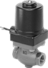
Valve Function

Minimum Temperature
Fitting Connection


Shape
Valve Position
Actuator Housing Material
Maximum Temperature
Pressure Class
Fitting Type
DFARS Specialty Metals
Export Control Classification Number (ECCN)