


How to Identify and Measure Fittings
Pipe size is an industry designation, not the actual size. View information about how to measure threaded and unthreaded pipe and pipe fittings.
More
About Actuated On/Off Valves
More
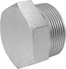
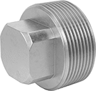
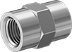
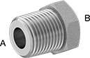
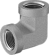
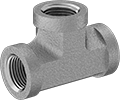
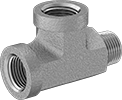
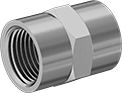
Low-Pressure Stainless Steel Threaded Pipe Fittings
Use these fittings in a low-pressure pipe line. 304 stainless steel fittings have very good corrosion resistance. 316 stainless steel fittings have excellent corrosion resistance. Adapters with weld end allow for a permanent connection.
Adapters for tanks create an inlet or outlet connection on the surface of any tank, pressure vessel, or drum.
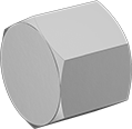
Plugs with magnet attract metal debris that could otherwise damage your system.
NPTF (Dryseal) threads and NPSL (National Pipe Straight Locknut) threads are compatible with NPT threads.
![]() For technical drawings and 3-D models, click on a part number.
For technical drawings and 3-D models, click on a part number.
- For Use With: Water, Oil, Gasoline, Diesel Fuel
316/316L Stainless Steel | ||||||
|---|---|---|---|---|---|---|
| Pipe Size | For Hole Dia. | OD | Lg. | For Tank OD | Each | |
NPTF Female × Weld | ||||||
| 1 1/2 | 2 1/16" | 3 1/4" | 1/4" | 21" | 0000000 | 000000 |
- For Use With: Air, Steam, Oil, Water, Natural Gas
- Pressure Class:
NPTF: 150 - Specifications Met:
Metric and BSPP: DIN 908 - Pipe Nipples and Pipe:
NPTF: Use Schedule 40 stainless steel - Flanges:
NPTF: Use Class 150 stainless steel
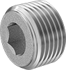
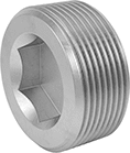
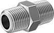
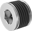
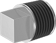
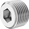
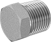
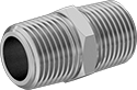
Premium Low-Pressure Stainless Steel Threaded Pipe Fittings with Certification
Unlike other stainless steel fittings, these are made in the U.S.A. for superior quality. As another marker of quality, they come with a certificate with a traceable lot number and test report that guarantees material composition. All fittings except 1/4" and 3/8" plugs and plugs with hex drive adhere to ANSI/MSS SP-114 standards for heat treating, material thickness, and marking. It’s the highest quality standard for Pressure Class 150 low-pressure stainless steel fittings. They also meet either ASTM A351 or A479 requirements for parts that will be used in pressure systems.
These stainless steel fittings are more corrosion resistant than steel fittings, and almost as strong. 316 stainless steel fittings are the most corrosion resistant. They stand up to wet environments, just like 304 stainless steel fittings, but unlike 304 stainless steel, they will not corrode from salt water, chlorine solutions, and chemicals.
![]() For technical drawings and 3-D models, click on a part number.
For technical drawings and 3-D models, click on a part number.
![]() Certificates with a traceable lot number are available for these products. Download certificates from ORDER HISTORY after your order ships.
Certificates with a traceable lot number are available for these products. Download certificates from ORDER HISTORY after your order ships.
- For Use With: Air, Natural Gas, Oil, Steam, Water
- Pressure Class: 150
- Fabrication: Heat Treated
- Specifications Met: See table
- Certification: Material Certificate with Traceable Lot Number
- Pipe Nipples and Pipe: Use Schedule 40 stainless steel
- Flanges: Use Class 150 stainless steel
316 Stainless Steel | ||||||
|---|---|---|---|---|---|---|
| Pipe Size | Drive Size | Max. Pressure | Max. Steam Pressure | Specifications Met | Each | |
NPTF Male | ||||||
| 1 1/2 | 1" | 270 psi @ 72° F | 150 psi @ 350° F | ASME B16.14, ASTM A276, ASTM A479 | 0000000 | 000000 |
- For Use With: Air, Natural Gas, Oil, Steam, Water
- Pressure Class: See table
- Fabrication: Heat Treated
- Specifications Met: See table
- Certification: Material Certificate with Traceable Lot Number
- Pipe Nipples and Pipe: Use Schedule 40 stainless steel
- Flanges: Use Class 150 stainless steel
316 Stainless Steel | |||||||
|---|---|---|---|---|---|---|---|
| Pipe Size | Drive Size | Pressure Class | Max. Pressure | Max. Steam Pressure | Specifications Met | Each | |
NPTF Male | |||||||
| 1 1/2 | 2" | 1000 | 1,000 psi @ 72° F | 650 psi @ 350° F | ANSI/MSS SP-114, ASTM A276, ASTM A479 | 0000000 | 000000 |
- For Use With: Air, Natural Gas, Oil, Steam, Water
- Pressure Class: See table
- Fabrication: Heat Treated
- Specifications Met: See table
- Certification: Material Certificate with Traceable Lot Number
- Pipe Nipples and Pipe: Use Schedule 40 stainless steel
- Flanges: Use Class 150 stainless steel
316 Stainless Steel | ||||||
|---|---|---|---|---|---|---|
| Pipe Size | Pressure Class | Max. Pressure | Max. Steam Pressure | Specifications Met | Each | |
NPTF Male | ||||||
| 1 1/2 | 1000 | 1,000 psi @ 72° F | 650 psi @ 350° F | ANSI/MSS SP-114, ASME B16.14, ASTM A276, ASTM A479 | 0000000 | 000000 |
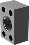
High-Pressure Stainless Steel Threaded SAE Pipe Flanges
Also known as Code 61 SAE hydraulic flanges, these let you create an access point in a high-pressure hydraulic line. To connect, bolt flanges to equipment, or bolt a flange with an O-ring groove surface to a flange with a flat surface of the same size. Flanges are 316 stainless steel for excellent corrosion resistance.
NPTF (Dryseal) threads are compatible with NPT threads.
![]() For technical drawings and 3-D models, click on a part number.
For technical drawings and 3-D models, click on a part number.

- Specifications Met: SAE J518, ISO 6162
- For Use With: Hydraulic Fluid
Flange | Bolt Hole | 316/316L Stainless Steel | |||||||||||
|---|---|---|---|---|---|---|---|---|---|---|---|---|---|
| Pipe Size | SAE Flange Size | Dash Size | Max. Pressure | Ht. | Wd. | Dp. | Mounting Hardware Included | For Bolt Dia. | Dia. | No. of | Ctr.-to-Ctr. | Each | |
NPTF | |||||||||||||
| 1 1/2 | 1 1/2 | 24 | 1,000 psi @ 72° F | 3 3/4" | 2 3/4" | 1 45/64" | No | 1/2" | 0.422" | 4 | 1.406", 2.75" | 0000000 | 0000000 |


- Specifications Met: SAE J518, ISO 6162
- For Use With: Hydraulic Fluid
Flange | Bolt Hole | 316/316L Stainless Steel | |||||||||||
|---|---|---|---|---|---|---|---|---|---|---|---|---|---|
| Pipe Size | SAE Flange Size | Dash Size | Max. Pressure | Ht. | Wd. | Dp. | Mounting Hardware Included | For Bolt Dia. | Dia. | No. of | Ctr.-to-Ctr. | Each | |
NPTF | |||||||||||||
| 1 1/2 | 1 1/2 | 24 | 1,000 psi @ 72° F | 3 3/4" | 2 3/4" | 1 45/64" | Yes | 1/2" | 0.531" | 4 | 1.406", 2.75" | 0000000 | 0000000 |
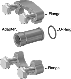
High-Pressure Stainless Steel Threaded SAE Two-Piece Pipe Flanges
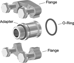
Combine an adapter with a two-piece pipe flange (sold separately) to build a customized flange connection. Also known as Code 61 or Code 62 split flanges, the two halves of the flange clamp around the adapter and bolt to another Code 61 or Code 62 flange. Flanges and adapters are 316 stainless steel which has excellent corrosion resistance.
NPTF (Dryseal) threads are compatible with NPT threads.
![]() For technical drawings and 3-D models, click on a part number.
For technical drawings and 3-D models, click on a part number.
- For Use With: Hydraulic Fluid
- Specifications Met: SAE J518, ISO 6162
316/316L Stainless Steel | ||||||
|---|---|---|---|---|---|---|
| Pipe Size | For SAE Flange Size | Dash Size | Max. Pressure | For Flanged Connection Surface | Each | |
NPTF | ||||||
| 1 1/2 | 1 1/2 | 24 | 3,000 psi @ 72° F | O-Ring Groove | 0000000 | 0000000 |
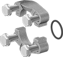
- For Use With: Hydraulic Fluid
- Specifications Met: SAE J518, ISO 6162
Flange | For Bolt | 316/316L Stainless Steel | |||||||||||
|---|---|---|---|---|---|---|---|---|---|---|---|---|---|
| SAE Flange Size | Dash Size | Max. Pressure | Ht. | Wd. | Dp. | Flanged Connection Surface | Mounting Hardware Included | For Bolt Dia. | Dia. | No. of | Ctr.-to-Ctr. | Each | |
Inch | |||||||||||||
| 1 1/2 | 24 | 3,000 psi @ 72° F | 3 11/16" | 3 1/4" | 1" | O-Ring Groove | Yes | 1/2" | 0.531" | 4 | 1.406", 2 3/4" | 0000000 | 0000000 |
Metric | |||||||||||||
| 1 1/2 | 24 | 3,000 psi @ 72° F | 94mm | 83mm | 25mm | O-Ring Groove | Yes | 12mm | 13mm | 4 | 36mm, 70mm | 0000000 | 000000 |
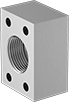
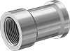
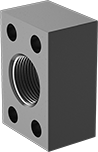
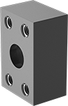
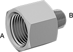
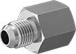
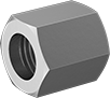
Extreme-Pressure Stainless Steel Threaded Pipe Fittings
With the strength to handle extreme pressures, these fittings can be used to connect equipment in hydraulic fluid lines. 316 stainless steel fittings have excellent corrosion resistance.
NPTF (Dryseal) threads are compatible with NPT threads.
![]() For technical drawings and 3-D models, click on a part number.
For technical drawings and 3-D models, click on a part number.
- For Use With: See table
- Specifications Met: See table
316 Stainless Steel | |||||||
|---|---|---|---|---|---|---|---|
| Pipe Size | Dash Size | Max. Pressure | Max. Steam Pressure | For Use With | Specifications Met | Each | |
NPTF Female | |||||||
| 1 1/2 | 24 | 2,400 psi @ 72° F | 2,400 psi @ 300° F | Hydraulic Fluid, Oil, Steam, Water | ASTM A479 | 000000000 | 0000000 |
- Specifications Met: See table
- For Use With: See table
316 Stainless Steel | ||||||||
|---|---|---|---|---|---|---|---|---|
| Pipe Size | Dash Size | Lg. | Max. Pressure | Max. Steam Pressure | For Use With | Specifications Met | Each | |
NPTF Male | ||||||||
| 1 1/2 | 24 | 2 39/64" | 3,600 psi @ 72° F | 3,600 psi @ 300° F | Hydraulic Fluid, Oil, Steam, Water | ASTM A479 | 000000000 | 0000000 |
- For Use With: Hydraulic Fluid, Oil, Steam, Water
- Specifications Met:
NPT × NPT: SAE J514
NPTF × NPTF: ASTM A479
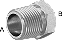
Pipe Size | Dash Size | 316 Stainless Steel | |||||
|---|---|---|---|---|---|---|---|
| (A) | (B) | (A) | (B) | Max. Pressure | Max. Steam Pressure | Each | |
NPTF Male × NPTF Female | |||||||
| 1 1/2 | 1 | 24 | 16 | 3,600 psi @ 72° F | 3,600 psi @ 300° F | 000000000 | 0000000 |
- For Use With: Hydraulic Fluid, Oil, Water
- Specifications Met:
BSPP: ISO 1179, ISO 8434-6
316 Stainless Steel | ||||
|---|---|---|---|---|
| Pipe Size | Dash Size | Max. Pressure | Each | |
NPTF Female | ||||
| 1 1/2 | 24 | 2,400 psi @ 72° F | 000000000 | 0000000 |
Low-Pressure Galvanized Iron and Steel Threaded Pipe Fittings with Sealant
The male threads on these fittings have a sealant applied for extra leak protection. Fittings are made of galvanized iron or steel, which have fair corrosion resistance. Also known as Pressure Class 125 or 150 fittings, they are for use in low-pressure applications.
NPTF (Dryseal) threads are compatible with NPT threads.
![]() For technical drawings and 3-D models, click on a part number.
For technical drawings and 3-D models, click on a part number.
- For Use With: Air, Oil, Natural Gas, Water
- Pressure Class: 150
- Specifications Met: See table
- Pipe Nipples and Pipe: Use Schedule 40 galvanized steel
- Flanges: Use Class 150 galvanized steel
| Pipe Size | Drive Size | Max. Pressure | Max. Steam Pressure | Specifications Met | Each | |
NPTF Male | ||||||
|---|---|---|---|---|---|---|
| 1 1/2 | 1" | 150 psi @ 72° F | Not Rated | ASME B16.14 | 0000000 | 000000 |
- For Use With: Air, Oil, Natural Gas, Water
- Pressure Class: 150
- Specifications Met: See table
- Pipe Nipples and Pipe: Use Schedule 40 galvanized steel
- Flanges: Use Class 150 galvanized steel
| Pipe Size | Plug Construction | Max. Pressure | Max. Steam Pressure | Specifications Met | Each | |
NPTF Male | ||||||
|---|---|---|---|---|---|---|
| 1 1/2 | Solid | 150 psi @ 72° F | Not Rated | ASME B16.14 | 0000000 | 000000 |
High-Pressure Steel Threaded SAE Pipe Flanges
Also known as Code 61 SAE hydraulic flanges, these let you create an access point in a high-pressure hydraulic line. To connect, bolt flanges to equipment, or bolt a flange with an O-ring groove surface to a flange with a flat surface of the same size. Flanges are for use in noncorrosive environments.
NPTF (Dryseal) threads are compatible with NPT threads.
![]() For technical drawings and 3-D models, click on a part number.
For technical drawings and 3-D models, click on a part number.
- For Use With: Hydraulic Fluid
- Specifications Met: SAE J518, ISO 6162
Flange | Bolt Hole | ||||||||||||
|---|---|---|---|---|---|---|---|---|---|---|---|---|---|
| Pipe Size | Dash Size | SAE Flange Size | Max. Pressure | Ht. | Wd. | Dp. | Mounting Hardware Included | For Bolt Dia. | Dia. | No. of | Ctr.-to-Ctr. | Each | |
NPTF | |||||||||||||
| 1 1/2 | 24 | 1 1/2 | 3,000 psi @ 72° F | 3 3/4" | 2 3/4" | 1 3/4" | No | 0.438" | 1/2" | 4 | 1.406", 2.75" | 0000000 | 000000 |

- For Use With: Hydraulic Fluid
- Specifications Met: SAE J518, ISO 6162
Flange | Bolt Hole | ||||||||||||
|---|---|---|---|---|---|---|---|---|---|---|---|---|---|
| Pipe Size | Dash Size | SAE Flange Size | Max. Pressure | Ht. | Wd. | Dp. | Mounting Hardware Included | For Bolt Dia. | Dia. | No. of | Ctr.-to-Ctr. | Each | |
NPTF—Inch | |||||||||||||
| 1 1/2 | 24 | 1 1/2 | 3,000 psi @ 72° F | 3 3/4" | 2 3/4" | 1 3/4" | Yes | 0.438" | 0.53" | 4 | 1.406", 2.75" | 0000000 | 000000 |
High-Pressure Steel Threaded SAE Two-Piece Pipe Flanges
Combine an adapter with a two-piece pipe flange (sold separately) to build a customized flange connection. Also known as Code 61 or Code 62 split flanges, the two halves of the flange clamp around the adapter and bolt to another Code 61 or Code 62 flange. The adapters have NPTF (Dryseal) threads, so they’re compatible with NPT threads. Flanges and adapters should be used in noncorrosive environments.
![]() For technical drawings and 3-D models, click on a part number.
For technical drawings and 3-D models, click on a part number.
- For Use With: Hydraulic Fluid
- Specifications Met: SAE J518, ISO 6162
Flange | Bolt Hole | ||||||||||||
|---|---|---|---|---|---|---|---|---|---|---|---|---|---|
| SAE Flange Size | Dash Size | Max. Pressure | Ht. | Wd. | Dp. | Flanged Connection Surface | Mounting Hardware Included | For Bolt Dia. | Dia. | No. of | Ctr.-to-Ctr. | Each | |
Inch | |||||||||||||
| 1 1/2 | 24 | 3,000 psi @ 72° F | 3 11/16" | 3 1/4" | 1" | O-Ring Groove | Yes | 0.438" | 0.47" | 4 | 1 13/32" , 2 3/4" | 000000 | 000000 |
| 1 1/2 | 24 | 6,000 psi @ 72° F | 4 7/16" | 3 3/4" | 1 11/16" | O-Ring Groove | Yes | 5/8" | 0.66" | 4 | 1 7/16" , 3 1/8" | 0000000 | 000000 |
Metric | |||||||||||||
| 1 1/2 | 24 | 3,000 psi @ 72° F | 94mm | 83mm | 25mm | O-Ring Groove | Yes | 12mm | 13mm | 4 | 36mm , 70mm | 0000000 | 00000 |
| 1 1/2 | 24 | 6,000 psi @ 72° F | 113mm | 95mm | 43mm | O-Ring Groove | Yes | 16mm | 17mm | 4 | 37mm , 80mm | 000000 | 000000 |
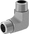
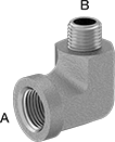
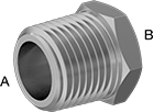
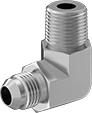
Compact Extreme-Pressure Steel Threaded Pipe Fittings
These fittings are strong enough to handle extreme pressures, yet small enough to fit into cramped spaces. They are galvanized and zinc-plated steel, which have better corrosion resistance than plain steel fittings.
Female x male 90° elbow adapters are also known as street elbows. Right-angle tees are also known as run tees.
NPTF (Dryseal) threads are compatible with NPT threads.
![]() For technical drawings and 3-D models, click on a part number.
For technical drawings and 3-D models, click on a part number.
- For Use With:
NPTF: Air, Hydraulic Fluid, Water
Metric: Air, Hydraulic Fluid, Oil, Water - Specifications Met:
NPTF: ASTM A108
Metric: DIN 7631, ISO 6149, ISO 9974
| Pipe Size | Dash Size | Max. Pressure | Material | Each | |
NPTF Female | |||||
|---|---|---|---|---|---|
| 1 1/2 | 24 | 2,000 psi @ 72° F | Zinc Plated Steel | 000000000 | 000000 |
- For Use With: See table
- Specifications Met:
NPTF and UN/UNF (SAE Straight): ASTM A108
BSPP: ISO 1179, ISO 8434-6
BSPT: DIN EN 10226-1, ISO 7-1
| Pipe Size | Dash Size | Max. Pressure | Material | For Use With | Each | |
NPTF Male | ||||||
|---|---|---|---|---|---|---|
| 1 1/2 | 24 | 3,000 psi @ 72° F | Zinc Plated Steel | Air, Hydraulic Fluid, Water | 000000000 | 000000 |
- For Use With: Air, Hydraulic Fluid, Water
- Specifications Met: ASTM A576
| Pipe Size | Dash Size | Max. Pressure | Material | Each | |
NPTF Female | |||||
|---|---|---|---|---|---|
| 1 1/2 | 24 | 1,500 psi @ 72° F | Zinc Plated Steel | 000000000 | 000000 |
- For Use With: Air, Hydraulic Fluid, Water
- Specifications Met: ASTM A576
| Pipe Size | Dash Size | Max. Pressure | Material | Each | |
NPTF Male | |||||
|---|---|---|---|---|---|
| 1 1/2 | 24 | 2,500 psi @ 72° F | Zinc Plated Steel | 000000000 | 000000 |
- For Use With: Air, Hydraulic Fluid, Water
- Specifications Met: ASTM A576
| Pipe Size (A) | Dash Size (A) | Pipe Size (B) | Dash Size (B) | Max. Pressure | Material | Each | |
NPT Female × NPTF Male | |||||||
|---|---|---|---|---|---|---|---|
| 1 1/2 | 24 | 1 1/2 | 24 | 1,500 psi @ 72° F | Zinc Plated Steel | 000000000 | 000000 |
- For Use With: Air, Hydraulic Fluid, Water
- Specifications Met: ASTM A576
| Pipe Size | Dash Size | Max. Pressure | Material | Each | |
NPTF Female | |||||
|---|---|---|---|---|---|
| 1 1/2 | 24 | 1,500 psi @ 72° F | Zinc Plated Steel | 000000000 | 0000000 |
- For Use With: Air, Hydraulic Fluid, Water
- Specifications Met: ASTM A576
| Pipe Size | Dash Size | Max. Pressure | Material | Each | |
NPTF Female × NPTF Male | |||||
|---|---|---|---|---|---|
| 1 1/2 | 20 | 1,500 psi @ 72° F | Zinc Plated Steel | 000000000 | 0000000 |
- For Use With:
NPTF and UN/UNF (SAE Straight): Air, Hydraulic Fluid, Water
Metric, BSPP and BSPT: Air, Hydraulic Fluid, Oil, Water - Specifications Met: See table
| Pipe Size | Dash Size | Drive Size | Max. Pressure | Material | Specifications Met | Each | |
NPTF Male | |||||||
|---|---|---|---|---|---|---|---|
| 1 1/2 | 24 | 1" | 3,000 psi @ 72° F | Zinc Plated Steel | ASTM A108 | 000000000 | 000000 |
- For Use With: See table
- Specifications Met: See table
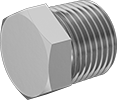
| Pipe Size | Dash Size | Plug Construction | Max. Pressure | Material | For Use With | Specifications Met | Each | |
NPTF Male | ||||||||
|---|---|---|---|---|---|---|---|---|
| 1 1/2 | 24 | Hollow | 3,000 psi @ 72° F | Zinc Plated Steel | Air, Hydraulic Fluid, Water | ASTM A108 | 000000000 | 000000 |
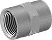
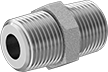
High-Pressure Brass Threaded Pipe Fittings
These fittings have the strength to handle high-pressure applications. They are brass for good corrosion resistance.
NPTF (Dryseal) threads are compatible with NPT threads.
![]() For technical drawings and 3-D models, click on a part number.
For technical drawings and 3-D models, click on a part number.
- For Use With: Air, Water, Natural Gas, Oil
- Specifications Met: See table
| Pipe Size | Max. Pressure | Each | |
NPTF Female | |||
|---|---|---|---|
| 1 1/2 | 1,000 psi @ 72° F | 00000000 | 000000 |
- For Use With: Air, Water, Natural Gas, Oil
- Specifications Met: See table
| Pipe Size | Max. Pressure | Each | |
NPTF Male | |||
|---|---|---|---|
| 1 1/2 | 1,000 psi @ 72° F | 000000000 | 000000 |
- For Use With: Air, Natural Gas, Oil, Water
Pipe Size | ||||
|---|---|---|---|---|
| (A) | (B) | Max. Pressure | Each | |
NPT Female × NPTF Male | ||||
| 2 | 1 1/2 | 500 psi @ 72° F | 000000000 | 0000000 |
- For Use With: Air, Water, Oil, Natural Gas
| Pipe Size | Max. Pressure | Each | |
NPTF Female | |||
|---|---|---|---|
| 1 1/2 | 1,000 psi @ 72° F | 000000000 | 000000 |
- For Use With: Air, Natural Gas, Oil, Water
Hollow | |||
|---|---|---|---|
| Pipe Size | Max. Pressure | Each | |
NPTF Male | |||
| 1 1/2 | 1,000 psi @ 72° F | 000000000 | 000000 |
Low-Pressure Aluminum Threaded Pipe Fittings
In addition to being lightweight, these aluminum fittings offer good corrosion resistance. Use them in low-pressure flow applications. To prevent cracking, do not tighten more than a 1/4-turn past hand tight.
Adapters for tanks weld onto the surface of any tank, pressure vessel, or drum to create a permanent inlet or outlet connection. NPTF (Dryseal) threads and NPSL (National Pipe Straight Locknut) threads are compatible with NPT threads.
![]() For technical drawings and 3-D models, click on a part number.
For technical drawings and 3-D models, click on a part number.
- For Use With: Water, Oil, Gasoline, Diesel Fuel
- Pipe Nipples and Pipe: Use Schedule 40 aluminum
| Pipe Size | For Hole Dia. | OD | Lg. | For Tank OD | Each | |
NPTF Female × Weld | ||||||
|---|---|---|---|---|---|---|
| 1 1/2 | 2" | 3 1/4" | 1/4" | 36" | 0000000 | 00000 |
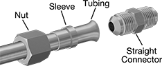
37° Flared Fittings for Steel Tubing
- For Use With: Air, Cutting Oil, Fuel Oil, Hydraulic Fluid, Mineral Oil
- Tubing: Use with seamless steel
- Specifications Met: SAE J514
Also known as JIC (Joint Industrial Council) fittings, these provide a tight metal-to-metal seal on tubing that is flared to 37°. They require a nut and a sleeve (ferrule) for each tube end. Nuts and sleeves are sold separately. Fittings are zinc-plated steel for fair corrosion resistance.
NPTF (Dryseal) threads are compatible with NPT threads.
![]() For technical drawings and 3-D models, click on a part number.
For technical drawings and 3-D models, click on a part number.
- Temperature Range: -60° to 400° F
| For Tube OD | Pipe Size | Material | Max. Pressure | Each | |
NPTF Threads | |||||
|---|---|---|---|---|---|
| 1 1/2" | 1 1/2 | Zinc-Plated Steel | 1,500 psi @ 72° F | 00000000 | 000000 |

- Temperature Range: -60° to 400° F
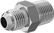
Fittings that swivel until tightened have a built-in nut that rotates 360° for easy installation.
Fittings with female tube end have an internal flare that mates with the male tube end of another fitting.
| For Tube OD | Pipe Size | Material | Max. Pressure | Each | |
NPTF Threads | |||||
|---|---|---|---|---|---|
| 1 1/2" | 1 1/2 | Zinc-Plated Steel | 2,000 psi @ 72° F | 000000000 | 000000 |
- Temperature Range: NPT: -65° to 400° F
NPTF and BSPT: -60° to 400° F
Metric and BSPP with O-Rings: -30° to 200°F
BSPP with Washers: -20° to 212° F
| For Tube OD | Pipe Size | Material | Max. Pressure | Each | |
NPTF Threads | |||||
|---|---|---|---|---|---|
| 1 1/2" | 1 1/2 | Zinc-Plated Steel | 1,000 psi @ 72° F | 000000000 | 000000 |
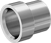
- Temperature Range: -60° to 400° F
Use these sleeves with a nut and fitting to provide a tight metal-to-metal seal on steel tubing that is flared to 37°. Sleeves are zinc-plated steel for fair corrosion resistance. They are also known as ferrules.
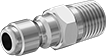
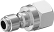
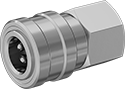
Open-Flow Quick-Disconnect Hose Couplings for Air and Water
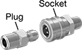
Couplings allow for maximum flow because there’s no shut-off valve in the plug or the socket. A complete coupling consists of a plug and a socket (both sold separately) that connect and disconnect quickly. Use them if you need frequent access to a line. All Open-Flow plugs are compatible with any of the Open-Flow sockets of the same coupling size, regardless of the pipe size. They are compatible with Hansen ST, Parker ST, and Perfecting E couplings.
Plugs are also known as nipples.
Sockets are sleeve-lock style. To connect, slide back the sleeve on the socket, insert the plug, and release the sleeve. To disconnect, slide back the sleeve and pull out the plug.
Brass plugs and sockets are softer than other metal plugs and sockets, so they’re easier to thread together. They have good corrosion resistance. Note: To ensure a correct fit, make sure that the plug and socket have the same coupling size.
Warning: There is no valve in these couplings. Stop the air and water flow before you disconnect the line.
![]() For technical drawings and 3-D models, click on a part number.
For technical drawings and 3-D models, click on a part number.
- Maximum Pressure: See table
- Temperature Range: -40° to 250° F
- Compatible With: Hansen ST Couplings, Parker ST Couplings, Perfecting E Couplings
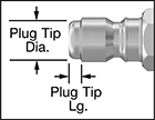
Plug Tip | ||||||
|---|---|---|---|---|---|---|
| Coupling Size | Lg. | Dia. | Pipe Size | Max. Pressure | Each | |
Brass | ||||||
| 1 1/2 | 3/16" | 1 3/4" | 1 1/2 | 1,400 psi @ 72° F | 0000000 | 0000000 |
- Maximum Pressure: See table
- Temperature Range: -40° to 250° F
- Compatible With: Hansen ST Couplings, Parker ST Couplings, Perfecting E Couplings
Plug Tip | ||||||
|---|---|---|---|---|---|---|
| Coupling Size | Lg. | Dia. | Pipe Size | Max. Pressure | Each | |
Brass | ||||||
| 1 1/2 | 3/16" | 1 3/4" | 1 1/2 | 1,400 psi @ 72° F | 0000000 | 0000000 |
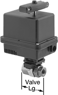
Motor-Driven On/Off Valves
- Valve Type: Ball
- For Use With: Water, Oil, Air, Argon, Helium, Neon, Steam, Xenon, Krypton
- Seal Material : PTFE Plastic
Also known as actuated ball valves, these have a motor that can handle high flow rates and pressures. All operate on electricity to automatically start and stop flow. Valves can be wired as normally closed unless actuated or normally open unless actuated. They don’t require a minimum pressure drop between the inlet and outlet for operation.
The actuator is directly mounted to the valve body to minimize movement and reduce wear. A visual flow indicator on the top of the actuator shows whether the valve is open or closed. The manual override allows you to operate the valve during power outages.
Full-port valves do not restrict flow.
Flow coefficient (Cv) is the amount of water (in gallons per minute) at 60° F that will flow through a fully open valve with a difference of 1 psi between the inlet and the outlet.
![]() For technical drawings and 3-D models, click on a part number.
For technical drawings and 3-D models, click on a part number.
Overall | ||||||||||||||
|---|---|---|---|---|---|---|---|---|---|---|---|---|---|---|
| Pipe Size | Gender | Thread Type | Port Type | Flow Coefficient (Cv) | Max. Pressure | Max. Steam Pressure | Pressure Drop | Actuation Time, sec. | Temp. Range, °F | Valve Lg. | Lg. | Ht. | Each | |
Brass Body with Screw Terminals | ||||||||||||||
Normally Open or Normally Closed—120V AC | ||||||||||||||
| 1 1/2 | Female | NPTF | Full | 120 | 720 psi @ 150° F | 150 psi @ 366° F | Zero Pressure Drop | 6 | -50° to 450° | 4 9/16" | 6 1/4" | 11 5/8" | 00000000 | 0000000 |
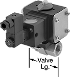
High-Flow Air-Driven On/Off Valves
Also known as actuated ball valves, these provide higher flow rates than other air-driven valves. They operate on compressed air to automatically start and stop flow faster than motor-driven valves. You must control the air to the actuator using either the included electric pilot valve or a manual on/off valve (not included).
Double-acting actuators require air pressure to open and close the valve. Once actuated, these valves remain actuated until air pressure is applied, so they do not have a valve starting position.
316 stainless steel valves have excellent corrosion resistance.
Zero pressure drop valves don’t require a minimum pressure drop between the inlet and outlet for operation.
Direct-mount actuators are directly attached to the valve body to minimize movement and reduce wear. Standard-port valves slightly restrict flow.
IP65 valves resist dust and low-pressure jets of water.
Valves with a visual flow indicator on the top of the actuator show whether the valve is open or closed.
Flow coefficient (Cv) is the amount of water (in gallons per minute) at 60° F that will flow through a fully open valve with a difference of 1 psi between the inlet and the outlet.
![]() For technical drawings and 3-D models, click on a part number.
For technical drawings and 3-D models, click on a part number.
- Valve Type: Ball
- For Use With: Water, Air, Steam
- Seal Material : Glass-Filled PTFE Plastic
Overall | Air | |||||||||||||
|---|---|---|---|---|---|---|---|---|---|---|---|---|---|---|
| Pipe Size | Gender | Thread Type | Flow Coefficient (Cv) | Max. Pressure | Max. Steam Pressure | Pressure Drop | Temp. Range, °F | Valve Lg. | Lg. | Ht. | Connection | Pressure Range, psi | Each | |
316 Stainless Steel Body with Standard Port and Visual Flow Indicator | ||||||||||||||
Double Acting: Air-to-Open, Air-to-Close—120V AC | ||||||||||||||
| 1 1/2 | Female | NPTF | 82 | 720 psi @ 150° F | 150 psi @ 366° F | Zero Pressure Drop | -50° to 450° | 4 1/4" | 5 1/2" | 8 1/8" | 1/8 NPT Female | 60 to 125 | 0000000 | 0000000 |
