Filter by
Horizontal Lift Capacity @ Material Thickness
Weight Capacity
Material Position
Application
Release Mechanism
Weight Capacity @ Diameter
Maximum Material Length @ Material Thickness
Weight
Overall Length
Width
Overall Width
Export Control Classification Number (ECCN)
DFARS Specialty Metals
Handle Length
Overall Height
Lifting Eye Height
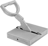
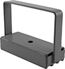
Lifting Magnets


Other Products