


Filter by
Weight Capacity @ Maximum Height
Weight Capacity @ Minimum Height
Adjustment Mechanism
U.S.–Mexico–Canada Agreement (USMCA) Qualifying
REACH
RoHS
DFARS Specialty Metals
Export Control Classification Number (ECCN)
Jack Posts
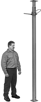 |
These steel jack posts provide temporary or permanent support for beams and joists. Mounting holes in the top and bottom plates let you fasten them in place for a secure installation.
Locking-Pin Adjustment—To adjust the height of locking-pin jack posts, extend the post to the approximate height needed and insert the locking pin through the hole to secure. Then turn the threaded handle counterclockwise to raise it up to 6" for more precise height adjustments.
Locking-Ring Adjustment—To adjust the height of locking-ring jack posts, slide the safety lock into the notch to secure at the approximate height needed. Then turn the 10" long handle for final height adjustments.
Ht. | Wt. Cap. | Base | Top Plate | |||||||||||||
|---|---|---|---|---|---|---|---|---|---|---|---|---|---|---|---|---|
Min. | Max. | @ Min. Ht. | @ Max. Ht. | Material | Wd. | Dp. | Wd. | Dp. | Mounting Hole Dia. (No. of) | Mounting Fasteners Included | Ctr.-to-Ctr. Adjustments | Handle Lg. | Each | |||
Locking-Pin Adjustment | ||||||||||||||||
| 78" | 138" | 6,400 lb. @ 78" | 3,800 lb. @ 138" | Steel | 4 3/4" | 4 3/4" | 4 3/4" | 4 3/4" | 9/16" (8) | No | 6" | — | 2929T15 | 0000000 | ||
| 120" | 216" | 9,300 lb. @ 120" | 2,700 lb. @ 216" | Steel | 4 3/4" | 4 3/4" | 4 3/4" | 4 3/4" | 9/16" (8) | No | 6" | — | 2929T16 | 000000 | ||
Locking-Ring Adjustment | ||||||||||||||||
| 16" | 24" | 18,000 lb. @ 16" | 18,000 lb. @ 24" | Steel | 4" | 4" | 4" | 4" | 3/8" (4), 5/8" (4) | No | 4" | 10" | 2946T5 | 000000 | ||
| 25" | 41" | 18,000 lb. @ 25" | 17,000 lb. @ 41" | Steel | 4" | 4" | 4" | 4" | 3/8" (4), 5/8" (4) | No | 4" | 10" | 2946T4 | 000000 | ||
| 40" | 64" | 18,000 lb. @ 40" | 17,000 lb. @ 64" | Steel | 4" | 4" | 4" | 4" | 3/8" (4), 5/8" (4) | No | 4" | 10" | 2946T3 | 000000 | ||
| 68" | 100" | 17,000 lb. @ 68" | 14,000 lb. @ 100" | Steel | 4" | 4" | 4" | 4" | 3/8" (4), 5/8" (4) | No | 4" | 10" | 2946T1 | 000000 | ||
