


Filter by
Shaft Diameter
Material
Diameter


Center Height
Length
Overall Width
Mounting Hole Center-to-Center
Overall Length

Width
Overall Height
Mounting Hole Diameter
Clamping Screw Thread Size
DFARS Specialty Metals
Performance
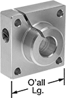
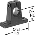
Easy-Access Base-Mount Linear Shaft Supports
Tee
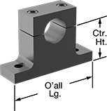 |
Tee supports have mounting flanges on the side. Mount these supports to a surface from either the top or bottom using the unthreaded holes.
Anodized 6061 Aluminum—Aluminum supports are lightweight and resist corrosion.
Overall | Mounting Hole | |||||||||||||
|---|---|---|---|---|---|---|---|---|---|---|---|---|---|---|
For Shaft Dia. | Lg. | Wd. | Ht. | Ctr. Ht. | Ctr. Ht. Tolerance | No. of | Ctr.-to-Ctr. | Dia. | Clamping Screw Thread Size | Fabrication | Each | |||
Black Anodized 6061 Aluminum | ||||||||||||||
| 1/4" | 1 1/2" | 1/2" | 1" | 11/16" | -0.002" to 0" | 2 | 1 1/8" | 0.16" | 6-32 | Machined | 1865K107 | 000000 | ||
| 3/8" | 1 5/8" | 9/16" | 1 1/8" | 3/4" | -0.002" to 0" | 2 | 1 1/4" | 0.16" | 6-32 | Machined | 1865K108 | 00000 | ||
| 1/2" | 2" | 5/8" | 1 1/2" | 1" | -0.002" to 0" | 2 | 1 1/2" | 0.19" | 8-32 | Machined | 1865K109 | 00000 | ||
| 5/8" | 2 1/2" | 11/16" | 1 1/2" | 1" | -0.002" to 0" | 2 | 1 7/8" | 0.22" | 10-24 | Machined | 1865K11 | 00000 | ||
| 3/4" | 2 3/4" | 3/4" | 1 13/16" | 1 1/4" | -0.002" to 0" | 2 | 2" | 0.22" | 10-24 | Machined | 1865K111 | 00000 | ||
| 1" | 3 1/4" | 1" | 2 3/16" | 1 1/2" | -0.002" to 0" | 2 | 2 1/2" | 0.28" | 1/4"-20 | Machined | 1865K112 | 00000 | ||
| 1 1/4" | 4" | 1 1/8" | 2 5/8" | 1 3/4" | -0.002" to 0" | 2 | 3" | 0.34" | 5/16"-18 | Machined | 1865K113 | 00000 | ||
| 1 1/2" | 4 3/4" | 1 1/4" | 3" | 2" | -0.002" to 0" | 2 | 3 1/2" | 0.34" | 5/16"-18 | Machined | 1865K114 | 00000 | ||
| 2" | 6" | 1 1/2" | 3 3/4" | 2 1/2" | -0.002" to 0" | 2 | 4 1/2" | 0.41" | 3/8"-16 | Machined | 1865K115 | 00000 | ||
| 8 mm | 32 mm | 10 mm | 23 mm | 15 mm | -0.05 mm to 0 mm | 2 | 25 mm | 4.5 mm | M2.5 | Machined | 1865K116 | 00000 | ||
| 12 mm | 40 mm | 12 mm | 30 mm | 20 mm | -0.05 mm to 0 mm | 2 | 32 mm | 5.5 mm | M3 | Machined | 1865K117 | 00000 | ||
| 16 mm | 50 mm | 16 mm | 38 mm | 25 mm | -0.05 mm to 0 mm | 2 | 40 mm | 5.5 mm | M4 | Machined | 1865K118 | 00000 | ||
| 20 mm | 60 mm | 20 mm | 45 mm | 30 mm | -0.05 mm to 0 mm | 2 | 45 mm | 5.5 mm | M5 | Machined | 1865K119 | 00000 | ||
| 25 mm | 74 mm | 25 mm | 55 mm | 35 mm | -0.05 mm to 0 mm | 2 | 60 mm | 6.6 mm | M6 | Machined | 1865K12 | 00000 | ||
| 30 mm | 84 mm | 28 mm | 63 mm | 40 mm | -0.05 mm to 0 mm | 2 | 68 mm | 9 mm | M8 | Machined | 1865K121 | 00000 | ||
| 40 mm | 108 mm | 32 mm | 80 mm | 50 mm | -0.05 mm to 0 mm | 2 | 86 mm | 11 mm | M10 | Machined | 1865K122 | 00000 | ||
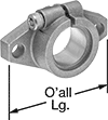
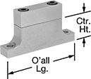
Low-Profile Tee
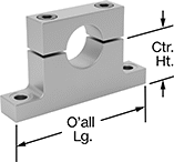 |
Low-profile tee supports are shorter and narrower than standard tee supports, so they are good for tight spaces. Mount these supports to a surface from either the top or bottom using the unthreaded holes.
304 Stainless Steel—Stainless steel supports resist corrosion better than aluminum supports.
Anodized 6061 Aluminum—Aluminum supports are lightweight and resist corrosion.
Overall | Mounting Hole | |||||||||||||
|---|---|---|---|---|---|---|---|---|---|---|---|---|---|---|
For Shaft Dia. | Lg. | Wd. | Ht. | Ctr. Ht. | Ctr. Ht. Tolerance | No. of | Ctr.-to-Ctr. | Dia. | Clamping Screw Thread Size | Fabrication | Each | |||
304 Stainless Steel | ||||||||||||||
| 1/4" | 1 5/8" | 3/8" | 7/8" | 9/16" | -0.002" to 0" | 2 | 1 1/4" | 0.16" | 6-32 | Machined | 4040N11 | 000000 | ||
| 3/8" | 1 3/4" | 3/8" | 1" | 5/8" | -0.002" to 0" | 2 | 1 3/8" | 0.16" | 6-32 | Machined | 4040N12 | 00000 | ||
| 1/2" | 2" | 1/2" | 1 3/16" | 3/4" | -0.002" to 0" | 2 | 1 5/8" | 0.19" | 8-32 | Machined | 4040N13 | 00000 | ||
| 5/8" | 2 5/8" | 1/2" | 1 7/16" | 15/16" | -0.002" to 0" | 2 | 2 1/8" | 0.22" | 10-24 | Machined | 4040N14 | 00000 | ||
| 3/4" | 2 3/4" | 1/2" | 1 9/16" | 1" | -0.002" to 0" | 2 | 2 1/4" | 0.22" | 10-24 | Machined | 4040N15 | 000000 | ||
| 1" | 3 3/16" | 3/4" | 1 15/16" | 1 1/4" | -0.002" to 0" | 2 | 2 5/8" | 0.28" | 1/4"-20 | Machined | 4040N16 | 000000 | ||
| 1 1/4" | 3 3/4" | 3/4" | 2 5/16" | 1 1/2" | -0.002" to 0" | 2 | 3 1/8" | 0.34" | 5/16"-18 | Machined | 4040N17 | 000000 | ||
| 1 1/2" | 4" | 3/4" | 2 11/16" | 1 3/4" | -0.002" to 0" | 2 | 3 3/8" | 0.34" | 5/16"-18 | Machined | 4040N18 | 000000 | ||
| 2" | 5" | 1 1/4" | 3 5/16" | 2 1/8" | -0.002" to 0" | 2 | 4 1/4" | 0.41" | 3/8"-16 | Machined | 4040N19 | 000000 | ||
| 8 mm | 44 mm | 10 mm | 21 mm | 12 mm | -0.05 mm to 0 mm | 2 | 35 mm | 4.5 mm | M4 | Machined | 4040N2 | 00000 | ||
| 10 mm | 46 mm | 12 mm | 25 mm | 14 mm | -0.05 mm to 0 mm | 2 | 38 mm | 4.5 mm | M4 | Machined | 4040N21 | 00000 | ||
| 12 mm | 48 mm | 12 mm | 25 mm | 14 mm | -0.05 mm to 0 mm | 2 | 40 mm | 4.5 mm | M4 | Machined | 4040N22 | 00000 | ||
| 16 mm | 62 mm | 13 mm | 31 mm | 18 mm | -0.05 mm to 0 mm | 2 | 50 mm | 5.5 mm | M5 | Machined | 4040N23 | 00000 | ||
| 20 mm | 65 mm | 13 mm | 36 mm | 22 mm | -0.05 mm to 0 mm | 2 | 54 mm | 5.5 mm | M5 | Machined | 4040N24 | 00000 | ||
| 25 mm | 80 mm | 19 mm | 44 mm | 27 mm | -0.05 mm to 0 mm | 2 | 66 mm | 6.6 mm | M6 | Machined | 4040N25 | 000000 | ||
| 30 mm | 96 mm | 19 mm | 52 mm | 32 mm | -0.05 mm to 0 mm | 2 | 78 mm | 9 mm | M8 | Machined | 4040N26 | 000000 | ||
| 40 mm | 108 mm | 19 mm | 66 mm | 40 mm | -0.05 mm to 0 mm | 2 | 90 mm | 9 mm | M8 | Machined | 4040N27 | 000000 | ||
Anodized 6061 Aluminum | ||||||||||||||
| 1/8" | 1 1/16" | 5/16" | 1/2" | 5/16" | -0.002" to 0" | 2 | 13/16" | 0.14" | 4-40 | Machined | 1865K31 | 00000 | ||
| 3/16" | 1 3/16" | 5/16" | 9/16" | 5/16" | -0.002" to 0" | 2 | 15/16" | 0.14" | 4-40 | Machined | 1865K32 | 00000 | ||
| 1/4" | 1 5/8" | 3/8" | 7/8" | 9/16" | -0.002" to 0" | 2 | 1 1/4" | 0.16" | 6-32 | Machined | 1865K1 | 00000 | ||
| 3/8" | 1 3/4" | 3/8" | 1" | 5/8" | -0.002" to 0" | 2 | 1 3/8" | 0.16" | 6-32 | Machined | 1865K2 | 00000 | ||
| 1/2" | 2" | 1/2" | 1 3/16" | 3/4" | -0.002" to 0" | 2 | 1 5/8" | 0.19" | 8-32 | Machined | 1865K3 | 00000 | ||
| 5/8" | 2 5/8" | 1/2" | 1 7/16" | 15/16" | -0.002" to 0" | 2 | 2 1/8" | 0.22" | 10-24 | Machined | 1865K4 | 00000 | ||
| 3/4" | 2 3/4" | 1/2" | 1 9/16" | 1" | -0.002" to 0" | 2 | 2 1/4" | 0.22" | 10-24 | Machined | 1865K5 | 00000 | ||
| 1" | 3 3/16" | 3/4" | 1 15/16" | 1 1/4" | -0.002" to 0" | 2 | 2 5/8" | 0.28" | 1/4"-20 | Machined | 1865K6 | 00000 | ||
| 1 1/4" | 3 3/4" | 3/4" | 2 5/16" | 1 1/2" | -0.002" to 0" | 2 | 3 1/8" | 0.34" | 5/16"-18 | Machined | 1865K7 | 00000 | ||
| 1 1/2" | 4" | 3/4" | 2 11/16" | 1 3/4" | -0.002" to 0" | 2 | 3 3/8" | 0.34" | 5/16"-18 | Machined | 1865K8 | 00000 | ||
| 2" | 5" | 1 1/4" | 3 5/16" | 2 1/8" | -0.002" to 0" | 2 | 4 1/4" | 0.41" | 3/8"-16 | Machined | 1865K9 | 00000 | ||
| 3 mm | 21 mm | 6 mm | 10 mm | 6 mm | -0.05 mm to 0 mm | 2 | 17 mm | 2.4 mm | M2 | Machined | 1865K33 | 00000 | ||
| 4 mm | 24 mm | 6 mm | 13 mm | 7 mm | -0.05 mm to 0 mm | 2 | 20 mm | 2.4 mm | M2 | Machined | 1865K34 | 00000 | ||
| 5 mm | 36 mm | 8 mm | 18 mm | 10 mm | -0.05 mm to 0 mm | 2 | 30 mm | 3.4 mm | M3 | Machined | 1865K35 | 00000 | ||
| 6 mm | 42 mm | 10 mm | 20 mm | 11 mm | -0.05 mm to 0 mm | 2 | 34 mm | 4.5 mm | M4 | Machined | 1865K36 | 00000 | ||
| 8 mm | 44 mm | 10 mm | 21 mm | 12 mm | -0.05 mm to 0 mm | 2 | 35 mm | 4.5 mm | M4 | Machined | 1865K21 | 00000 | ||
| 10 mm | 46 mm | 12 mm | 25 mm | 14 mm | -0.05 mm to 0 mm | 2 | 38 mm | 4.5 mm | M4 | Machined | 1865K22 | 00000 | ||
| 12 mm | 48 mm | 12 mm | 25 mm | 14 mm | -0.05 mm to 0 mm | 2 | 40 mm | 4.5 mm | M4 | Machined | 1865K23 | 00000 | ||
| 16 mm | 62 mm | 13 mm | 31 mm | 18 mm | -0.05 mm to 0 mm | 2 | 50 mm | 5.5 mm | M5 | Machined | 1865K101 | 00000 | ||
| 20 mm | 65 mm | 14 mm | 36 mm | 22 mm | -0.05 mm to 0 mm | 2 | 54 mm | 5.5 mm | M5 | Machined | 1865K24 | 00000 | ||
| 25 mm | 80 mm | 19 mm | 44 mm | 27 mm | -0.05 mm to 0 mm | 2 | 66 mm | 6.6 mm | M6 | Machined | 1865K102 | 00000 | ||
| 30 mm | 96 mm | 19 mm | 52 mm | 32 mm | -0.05 mm to 0 mm | 2 | 78 mm | 9 mm | M8 | Machined | 1865K103 | 00000 | ||
| 35 mm | 100 mm | 19 mm | 60 mm | 34 mm | -0.05 mm to 0 mm | 2 | 84 mm | 9 mm | M8 | Machined | 1865K104 | 00000 | ||
| 40 mm | 108 mm | 19 mm | 66 mm | 40 mm | -0.05 mm to 0 mm | 2 | 90 mm | 9 mm | M8 | Machined | 1865K105 | 00000 | ||
| 50 mm | 120 mm | 25 mm | 75 mm | 45 mm | -0.05 mm to 0 mm | 2 | 100 mm | 9 mm | M8 | Machined | 1865K106 | 00000 | ||
L-Shaped
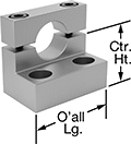 |
L-shaped supports have a mounting flange on one face of the support. They are narrower than tee supports. Mount these supports to a surface from either the top or bottom using the unthreaded holes.
Anodized 6061 Aluminum—Aluminum supports are lightweight and resist corrosion.
Overall | Mounting Hole | ||||||||||||||
|---|---|---|---|---|---|---|---|---|---|---|---|---|---|---|---|
For Shaft Dia. | Base Wd. | Lg. | Wd. | Ht. | Ctr. Ht. | Ctr. Ht. Tolerance | No. of | Ctr.-to-Ctr. | Dia. | Clamping Screw Thread Size | Fabrication | Each | |||
Anodized 6061 Aluminum | |||||||||||||||
| 3/8" | 9/16" | 1" | 15/16" | 1" | 5/8" | -0.002" to 0" | 2 | 1/2" | 0.18" | 8-32 | Machined | 1865K41 | 000000 | ||
| 1/2" | 11/16" | 1 1/4" | 1 3/16" | 1 3/16" | 3/4" | -0.002" to 0" | 2 | 3/4" | 0.2" | 8-32 | Machined | 1865K42 | 00000 | ||
| 3/4" | 11/16" | 1 11/16" | 1 3/16" | 1 9/16" | 1" | -0.002" to 0" | 2 | 1" | 0.27" | 10-24 | Machined | 1865K43 | 00000 | ||
| 1" | 11/16" | 2" | 1 7/16" | 1 15/16" | 1 1/4" | -0.002" to 0" | 2 | 1 1/2" | 0.27" | 1/4"-20 | Machined | 1865K44 | 00000 | ||
| 10 mm | 12 mm | 28 mm | 24 mm | 25 mm | 14 mm | -0.05 mm to 0 mm | 2 | 16 mm | 5 mm | M4 | Machined | 1865K45 | 00000 | ||
| 12 mm | 12 mm | 30 mm | 24 mm | 25 mm | 14 mm | -0.05 mm to 0 mm | 2 | 19 mm | 5 mm | M4 | Machined | 1865K46 | 00000 | ||
| 20 mm | 17 mm | 43 mm | 30 mm | 36 mm | 22 mm | -0.05 mm to 0 mm | 2 | 29 mm | 6 mm | M5 | Machined | 1865K47 | 00000 | ||
| 25 mm | 17 mm | 52 mm | 36 mm | 44 mm | 27 mm | -0.05 mm to 0 mm | 2 | 35 mm | 7 mm | M6 | Machined | 1865K48 | 00000 | ||
Rectangular
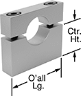 |
Rectangular supports do not have a mounting flange. They are the most compact support we offer. Mount these supports to a surface from the bottom using the tapped holes.
Anodized 6061 Aluminum—Aluminum supports are lightweight and resist corrosion.
Overall | Mounting Hole | |||||||||||||
|---|---|---|---|---|---|---|---|---|---|---|---|---|---|---|
For Shaft Dia. | Lg. | Wd. | Ht. | Ctr. Ht. | Ctr. Ht. Tolerance | No. of | Ctr.-to-Ctr. | Clamping Screw Thread Size | Fabrication | Mounting Thread Size | Each | |||
Anodized 6061 Aluminum | ||||||||||||||
| 3/8" | 1" | 3/8" | 1" | 5/8" | -0.002" to 0" | 2 | 11/16" | 6-32 | Machined | 6-32 | 1865K51 | 000000 | ||
| 1/2" | 1 1/4" | 1/2" | 1 3/16" | 3/4" | -0.002" to 0" | 2 | 13/16" | 8-32 | Machined | 8-32 | 1865K52 | 00000 | ||
| 3/4" | 1 11/16" | 1/2" | 1 9/16" | 1" | -0.002" to 0" | 2 | 1 3/16" | 10-24 | Machined | 10-24 | 1865K53 | 00000 | ||
| 1" | 2" | 3/4" | 1 15/16" | 1 1/4" | -0.002" to 0" | 2 | 1 1/2" | 1/4"-20 | Machined | 1/4"-20 | 1865K54 | 00000 | ||
| 10 mm | 30 mm | 12 mm | 25 mm | 14 mm | -0.05 mm to 0 mm | 2 | 18 mm | M4 | Machined | M4 × 0.7 mm | 1865K55 | 00000 | ||
| 12 mm | 30 mm | 12 mm | 25 mm | 14 mm | -0.05 mm to 0 mm | 2 | 20 mm | M4 | Machined | M4 × 0.7 mm | 1865K56 | 00000 | ||
| 20 mm | 42 mm | 13 mm | 36 mm | 22 mm | -0.05 mm to 0 mm | 2 | 30 mm | M5 | Machined | M5 × 0.8 mm | 1865K57 | 00000 | ||
| 25 mm | 52 mm | 19 mm | 43 mm | 27 mm | -0.05 mm to 0 mm | 2 | 38 mm | M6 | Machined | M6 × 1 mm | 1865K58 | 00000 | ||
Flange-Mount Linear Shaft Supports
Overall | Mounting Hole | ||||||||||||
|---|---|---|---|---|---|---|---|---|---|---|---|---|---|
For Shaft Dia. | Lg. | Wd. | Ht. | Flange Thk. | No. of | Ctr.-to-Ctr. | Dia. | Clamping Screw Thread Size | Fabrication | Each | |||
6061 Aluminum | |||||||||||||
 | |||||||||||||
| 1/4" | 1 1/2" | 3/4" | 1 1/2" | 3/8" | 4 | 1" | 0.16" | 6-32 | Machined | 57745K17 | 000000 | ||
| 3/8" | 1 1/2" | 3/4" | 1 1/2" | 3/8" | 4 | 1" | 0.16" | 6-32 | Machined | 57745K18 | 00000 | ||
| 1/2" | 1 5/8" | 7/8" | 1 5/8" | 1/2" | 4 | 1 1/4" | 0.18" | 8-32 | Machined | 57745K21 | 00000 | ||
| 5/8" | 2" | 7/8" | 2" | 1/2" | 4 | 1 1/2" | 0.18" | 8-32 | Machined | 57745K19 | 00000 | ||
| 3/4" | 2 3/8" | 1" | 2 3/8" | 5/8" | 4 | 1 3/4" | 0.21" | 10-32 | Machined | 57745K22 | 00000 | ||
| 1" | 2 3/4" | 1 1/4" | 2 3/4" | 5/8" | 4 | 2 1/8" | 0.27" | 1/4"-20 | Machined | 57745K23 | 00000 | ||
| 1 1/4" | 3 1/8" | 1 3/8" | 3 1/8" | 3/4" | 4 | 2 3/8" | 0.27" | 1/4"-20 | Machined | 57745K24 | 00000 | ||
| 1 1/2" | 3 1/2" | 1 5/8" | 3 1/2" | 3/4" | 4 | 2 1/2" | 0.33" | 5/16"-18 | Machined | 57745K25 | 000000 | ||
| 2" | 4" | 2" | 4" | 7/8" | 4 | 2 7/8" | 0.33" | 5/16"-18 | Machined | 57745K26 | 000000 | ||
1060 Aluminum | |||||||||||||
 | |||||||||||||
| 10 mm | 43 mm | 10 mm | 24 mm | 5 mm | 2 | 32 mm | 5 mm | M4 | Cast | 62645K41 | 00000 | ||
| 12 mm | 47 mm | 13 mm | 28 mm | 7 mm | 2 | 36 mm | 5 mm | M4 | Cast | 62645K38 | 00000 | ||
| 16 mm | 50 mm | 16 mm | 31 mm | 8 mm | 2 | 40 mm | 5 mm | M4 | Cast | 62645K39 | 00000 | ||
| 20 mm | 60 mm | 20 mm | 37 mm | 8 mm | 2 | 48 mm | 7 mm | M5 | Cast | 62645K42 | 00000 | ||
| 25 mm | 70 mm | 25 mm | 42 mm | 10 mm | 2 | 56 mm | 7 mm | M5 | Cast | 62645K43 | 00000 | ||
| 30 mm | 80 mm | 30 mm | 50 mm | 12 mm | 2 | 64 mm | 9 mm | M6 | Cast | 62645K44 | 00000 | ||
| 35 mm | 92 mm | 35 mm | 58 mm | 14 mm | 2 | 72 mm | 12 mm | M8 | Cast | 62645K45 | 00000 | ||
| 40 mm | 102 mm | 40 mm | 67 mm | 16 mm | 2 | 80 mm | 12 mm | M10 | Cast | 62645K46 | 00000 | ||
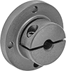
Easy-Access Flange-Mount Linear Shaft Supports
Overall | Mounting Hole | ||||||||||||||
|---|---|---|---|---|---|---|---|---|---|---|---|---|---|---|---|
For Shaft Dia. | Dia. | Lg. | Wd. | Ht. | Flange Thk. | Bolt Circle Dia. | No. of | Ctr.-to-Ctr. | Dia. | Clamping Screw Thread Size | Fabrication | Each | |||
1117 Carbon Steel | |||||||||||||||
 | |||||||||||||||
| 1/4" | 1 5/8" | — | 3/4" | — | 1/4" | 1 11/32" | 4 | — | 0.15" | 6-32 | Machined | 1870K1 | 000000 | ||
| 3/8" | 1 5/8" | — | 3/4" | — | 1/4" | 1 11/32" | 4 | — | 0.15" | 6-32 | Machined | 1870K2 | 00000 | ||
| 1/2" | 2 1/4" | — | 1" | — | 5/16" | 1 3/4" | 4 | — | 0.177" | 8-32 | Machined | 1870K3 | 00000 | ||
| 5/8" | 2 5/8" | — | 1" | — | 5/16" | 2 1/8" | 4 | — | 0.201" | 10-32 | Machined | 1870K4 | 00000 | ||
| 3/4" | 3" | — | 1" | — | 5/16" | 2 3/8" | 4 | — | 0.266" | 1/4"-28 | Machined | 1870K5 | 00000 | ||
| 1" | 3 1/4" | — | 1 5/8" | — | 3/8" | 2 3/4" | 4 | — | 0.266" | 1/4"-28 | Machined | 1870K6 | 00000 | ||
| 1 1/4" | 3 1/2" | — | 1 5/8" | — | 3/8" | 3" | 4 | — | 0.266" | 1/4"-28 | Machined | 1870K7 | 000000 | ||
| 1 1/2" | 3 3/4" | — | 2" | — | 13/32" | 3 1/4" | 4 | — | 0.266" | 1/4"-28 | Machined | 1870K8 | 000000 | ||
| 2" | 4 1/2" | — | 2 3/8" | — | 1/2" | 3 7/8" | 4 | — | 0.328" | 5/16"-24 | Machined | 1870K9 | 000000 | ||
304 Stainless Steel | |||||||||||||||
 | |||||||||||||||
| 3/8" | — | 1 7/16" | 5/8" | 1 7/16" | 3/16" | — | 4 | 1 1/8" | 0.17" | 6-32 | Machined | 1870K11 | 00000 | ||
| 1/2" | — | 1 11/16" | 3/4" | 1 11/16" | 1/4" | — | 4 | 1 1/4" | 0.2" | 8-32 | Machined | 1870K12 | 000000 | ||
| 3/4" | — | 2 3/16" | 3/4" | 2 3/16" | 1/4" | — | 4 | 1 3/4" | 0.22" | 10-24 | Machined | 1870K13 | 000000 | ||
| 1" | — | 2 11/16" | 1 1/16" | 2 11/16" | 5/16" | — | 4 | 2 1/8" | 0.28" | 1/4"-20 | Machined | 1870K14 | 000000 | ||
| 10 mm | — | 43 mm | 19 mm | 43 mm | 6 mm | — | 4 | 32 mm | 4.8 mm | M4 | Machined | 1870K35 | 000000 | ||
| 12 mm | — | 43 mm | 19 mm | 43 mm | 6 mm | — | 4 | 32 mm | 4.8 mm | M4 | Machined | 1870K32 | 000000 | ||
| 20 mm | — | 55 mm | 20 mm | 55 mm | 6 mm | — | 4 | 42 mm | 5.8 mm | M5 | Machined | 1870K36 | 000000 | ||
| 25 mm | — | 68 mm | 28 mm | 68 mm | 8 mm | — | 4 | 54 mm | 7.1 mm | M6 | Machined | 1870K34 | 000000 | ||
Anodized 6061 Aluminum | |||||||||||||||
| |||||||||||||||
| 8 mm | — | 36 mm | 16 mm | 36 mm | 5 mm | — | 4 | 28 mm | 4.8 mm | M4 | Machined | 1870K29 | 00000 | ||
| 10 mm | — | 43 mm | 19 mm | 43 mm | 6 mm | — | 4 | 32 mm | 4.8 mm | M4 | Machined | 1870K22 | 00000 | ||
| 12 mm | — | 43 mm | 19 mm | 43 mm | 6 mm | — | 4 | 32 mm | 4.8 mm | M4 | Machined | 1870K51 | 00000 | ||
| 16 mm | — | 55 mm | 20 mm | 55 mm | 6 mm | — | 4 | 42 mm | 5.8 mm | M5 | Machined | 1870K24 | 00000 | ||
| 20 mm | — | 55 mm | 20 mm | 55 mm | 6 mm | — | 4 | 42 mm | 5.8 mm | M5 | Machined | 1870K25 | 00000 | ||
| 25 mm | — | 68 mm | 28 mm | 68 mm | 8 mm | — | 4 | 54 mm | 7.1 mm | M6 | Machined | 1870K26 | 00000 | ||
| 30 mm | — | 87 mm | 28 mm | 87 mm | 8 mm | — | 4 | 64 mm | 9.9 mm | M8 | Machined | 1870K27 | 00000 | ||
| 40 mm | — | 100 mm | 30 mm | 100 mm | 10 mm | — | 4 | 75 mm | 9.9 mm | M8 | Machined | 1870K28 | 00000 | ||
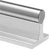
Support-Rail Shafts
 |
Shafts | Replacement Shafts | |||||||||||||
|---|---|---|---|---|---|---|---|---|---|---|---|---|---|---|
Lg. | Dia. Tolerance | Ctr. Ht. | Overall Wd. | Mounting Hole Dia. | Hardness | Hardness Rating | Surface Smoothness, μin | Support Rail Material | Each | Each | ||||
Steel | ||||||||||||||
1/2" Diameter | ||||||||||||||
| 24" | -0.001" to -0.0005" | 1 1/8" | 1 1/2" | 5/32" | Rockwell C60 | Extra Hard | 8 | 6061 Aluminum | 59585K83 | 0000000 | 6499K53 | 0000000 | ||
| 48" | -0.001" to -0.0005" | 1 1/8" | 1 1/2" | 5/32" | Rockwell C60 | Extra Hard | 8 | 6061 Aluminum | 59585K53 | 000000 | 6499K73 | 000000 | ||
5/8" Diameter | ||||||||||||||
| 24" | -0.001" to -0.0005" | 1 1/8" | 1 5/8" | 3/16" | Rockwell C60 | Extra Hard | 8 | 6061 Aluminum | 59585K89 | 000000 | 6499K59 | 000000 | ||
| 48" | -0.001" to -0.0005" | 1 1/8" | 1 5/8" | 3/16" | Rockwell C60 | Extra Hard | 8 | 6061 Aluminum | 59585K59 | 000000 | 6499K79 | 000000 | ||
3/4" Diameter | ||||||||||||||
| 24" | -0.001" to -0.0005" | 1 1/2" | 1 3/4" | 7/32" | Rockwell C60 | Extra Hard | 8 | 6061 Aluminum | 59585K84 | 000000 | 6499K54 | 000000 | ||
| 48" | -0.001" to -0.0005" | 1 1/2" | 1 3/4" | 7/32" | Rockwell C60 | Extra Hard | 8 | 6061 Aluminum | 59585K54 | 000000 | 6499K74 | 000000 | ||
1" Diameter | ||||||||||||||
| 24" | -0.001" to -0.0005" | 1 3/4" | 2 1/8" | 9/32" | Rockwell C60 | Extra Hard | 8 | 6061 Aluminum | 59585K85 | 000000 | 6499K55 | 000000 | ||
| 48" | -0.001" to -0.0005" | 1 3/4" | 2 1/8" | 9/32" | Rockwell C60 | Extra Hard | 8 | 6061 Aluminum | 59585K55 | 000000 | 6499K75 | 000000 | ||
1 1/4" Diameter | ||||||||||||||
| 24" | -0.001" to -0.0005" | 2 1/8" | 2 1/2" | 11/32" | Rockwell C60 | Extra Hard | 8 | 6061 Aluminum | 59585K86 | 000000 | 6499K56 | 000000 | ||
| 48" | -0.001" to -0.0005" | 2 1/8" | 2 1/2" | 11/32" | Rockwell C60 | Extra Hard | 8 | 6061 Aluminum | 59585K56 | 000000 | 6499K76 | 000000 | ||
1 1/2" Diameter | ||||||||||||||
| 24" | -0.0011" to -0.0006" | 2 1/2" | 3" | 11/32" | Rockwell C60 | Extra Hard | 8 | 6061 Aluminum | 59585K87 | 000000 | 6499K57 | 000000 | ||
| 48" | -0.0011" to -0.0006" | 2 1/2" | 3" | 11/32" | Rockwell C60 | Extra Hard | 8 | 6061 Aluminum | 59585K57 | 000000 | 6499K77 | 000000 | ||
12 mm Diameter | ||||||||||||||
| 600 mm | -0.011 mm to 0 mm | 28 mm | 43 mm | 4.5 mm | Rockwell C60 | Extra Hard | 12 | 6063 Aluminum | 59585K71 | 000000 | ——— | 0 | ||
| 1,200 mm | -0.011 mm to 0 mm | 28 mm | 43 mm | 4.5 mm | Rockwell C60 | Extra Hard | 12 | 6063 Aluminum | 59585K91 | 000000 | ——— | 0 | ||
16 mm Diameter | ||||||||||||||
| 600 mm | -0.011 mm to 0 mm | 30 mm | 48 mm | 5.5 mm | Rockwell C60 | Extra Hard | 12 | 6063 Aluminum | 59585K11 | 000000 | ——— | 0 | ||
| 1,200 mm | -0.011 mm to 0 mm | 30 mm | 48 mm | 5.5 mm | Rockwell C60 | Extra Hard | 12 | 6063 Aluminum | 59585K12 | 000000 | ——— | 0 | ||
20 mm Diameter | ||||||||||||||
| 600 mm | -0.013 mm to 0 mm | 38 mm | 56 mm | 6.6 mm | Rockwell C60 | Extra Hard | 12 | 6063 Aluminum | 59585K13 | 000000 | ——— | 0 | ||
| 1,200 mm | -0.013 mm to 0 mm | 38 mm | 56 mm | 6.6 mm | Rockwell C60 | Extra Hard | 12 | 6063 Aluminum | 59585K14 | 000000 | ——— | 0 | ||
25 mm Diameter | ||||||||||||||
| 1,200 mm | -0.013 mm to 0 mm | 42 mm | 60 mm | 6.6 mm | Rockwell C60 | Extra Hard | 12 | 6063 Aluminum | 59585K94 | 000000 | ——— | 0 | ||
30 mm Diameter | ||||||||||||||
| 1,200 mm | -0.013 mm to 0 mm | 53 mm | 74 mm | 9 mm | Rockwell C60 | Extra Hard | 12 | 6063 Aluminum | 59585K16 | 000000 | ——— | 0 | ||
Highly Wear-Resistant 440C Stainless Steel | ||||||||||||||
1/2" Diameter | ||||||||||||||
| 24" | -0.001" to -0.0005" | 1 1/8" | 1 1/2" | 5/32" | Rockwell C50 | Extra Hard | 8 | 6061 Aluminum | 6557K21 | 000000 | 6526K53 | 000000 | ||
| 48" | -0.001" to -0.0005" | 1 1/8" | 1 1/2" | 5/32" | Rockwell C50 | Extra Hard | 8 | 6061 Aluminum | 6557K31 | 000000 | 6526K73 | 000000 | ||
5/8" Diameter | ||||||||||||||
| 24" | -0.001" to -0.0005" | 1 1/8" | 1 5/8" | 3/16" | Rockwell C50 | Extra Hard | 8 | 6061 Aluminum | 6557K22 | 000000 | 6526K59 | 000000 | ||
| 48" | -0.001" to -0.0005" | 1 1/8" | 1 5/8" | 3/16" | Rockwell C50 | Extra Hard | 8 | 6061 Aluminum | 6557K32 | 000000 | 6526K79 | 000000 | ||
3/4" Diameter | ||||||||||||||
| 24" | -0.001" to -0.0005" | 1 1/2" | 1 3/4" | 7/32" | Rockwell C50 | Extra Hard | 8 | 6061 Aluminum | 6557K23 | 000000 | 6526K54 | 000000 | ||
| 48" | -0.001" to -0.0005" | 1 1/2" | 1 3/4" | 7/32" | Rockwell C50 | Extra Hard | 8 | 6061 Aluminum | 6557K33 | 000000 | 6526K74 | 000000 | ||
1" Diameter | ||||||||||||||
| 24" | -0.001" to -0.0005" | 1 3/4" | 2 1/8" | 9/32" | Rockwell C50 | Extra Hard | 8 | 6061 Aluminum | 6557K24 | 000000 | 6526K55 | 000000 | ||
| 48" | -0.001" to -0.0005" | 1 3/4" | 2 1/8" | 9/32" | Rockwell C50 | Extra Hard | 8 | 6061 Aluminum | 6557K34 | 000000 | 6526K75 | 000000 | ||
1 1/4" Diameter | ||||||||||||||
| 24" | -0.001" to -0.0005" | 2 1/8" | 2 1/2" | 11/32" | Rockwell C50 | Extra Hard | 8 | 6061 Aluminum | 6557K25 | 000000 | 6526K56 | 000000 | ||
| 48" | -0.001" to -0.0005" | 2 1/8" | 2 1/2" | 11/32" | Rockwell C50 | Extra Hard | 8 | 6061 Aluminum | 6557K35 | 00000000 | ——— | 0 | ||
1 1/2" Diameter | ||||||||||||||
| 24" | -0.0011" to -0.0006" | 2 1/2" | 3" | 11/32" | Rockwell C50 | Extra Hard | 8 | 6061 Aluminum | 6557K26 | 000000 | ——— | 0 | ||
| 48" | -0.0011" to -0.0006" | 2 1/2" | 3" | 11/32" | Rockwell C50 | Extra Hard | 8 | 6061 Aluminum | 6557K36 | 00000000 | 6526K77 | 000000 | ||
Lightweight Ceramic-Coated Aluminum | ||||||||||||||
1/2" Diameter | ||||||||||||||
| 6" | -0.0012" to -0.0004" | 1 1/8" | 1 1/2" | 5/32" | Rockwell C70 | Ultra Hard | 12 | 6063 Aluminum | 1049K11 | 00000 | ——— | 0 | ||
| 9" | -0.0012" to -0.0004" | 1 1/8" | 1 1/2" | 5/32" | Rockwell C70 | Ultra Hard | 12 | 6063 Aluminum | 1049K12 | 00000 | ——— | 0 | ||
| 12" | -0.0012" to -0.0004" | 1 1/8" | 1 1/2" | 5/32" | Rockwell C70 | Ultra Hard | 12 | 6063 Aluminum | 1049K13 | 00000 | ——— | 0 | ||
| 18" | -0.0012" to -0.0004" | 1 1/8" | 1 1/2" | 5/32" | Rockwell C70 | Ultra Hard | 12 | 6063 Aluminum | 1049K14 | 000000 | ——— | 0 | ||
| 24" | -0.0012" to -0.0004" | 1 1/8" | 1 1/2" | 5/32" | Rockwell C70 | Ultra Hard | 12 | 6063 Aluminum | 1049K15 | 000000 | ——— | 0 | ||
3/4" Diameter | ||||||||||||||
| 6" | -0.0012" to -0.0004" | 1 1/2" | 1 3/4" | 7/32" | Rockwell C70 | Ultra Hard | 12 | 6063 Aluminum | 1049K21 | 00000 | ——— | 0 | ||
| 9" | -0.0012" to -0.0004" | 1 1/2" | 1 3/4" | 7/32" | Rockwell C70 | Ultra Hard | 12 | 6063 Aluminum | 1049K22 | 00000 | ——— | 0 | ||
| 12" | -0.0012" to -0.0004" | 1 1/2" | 1 3/4" | 7/32" | Rockwell C70 | Ultra Hard | 12 | 6063 Aluminum | 1049K23 | 000000 | ——— | 0 | ||
| 18" | -0.0012" to -0.0004" | 1 1/2" | 1 3/4" | 7/32" | Rockwell C70 | Ultra Hard | 12 | 6063 Aluminum | 1049K24 | 000000 | ——— | 0 | ||
| 24" | -0.0012" to -0.0004" | 1 1/2" | 1 3/4" | 7/32" | Rockwell C70 | Ultra Hard | 12 | 6063 Aluminum | 1049K25 | 000000 | ——— | 0 | ||
1" Diameter | ||||||||||||||
| 6" | -0.0012" to -0.0004" | 1 3/4" | 2 1/8" | 9/32" | Rockwell C70 | Ultra Hard | 12 | 6063 Aluminum | 1049K31 | 00000 | ——— | 0 | ||
| 9" | -0.0012" to -0.0004" | 1 3/4" | 2 1/8" | 9/32" | Rockwell C70 | Ultra Hard | 12 | 6063 Aluminum | 1049K32 | 00000 | ——— | 0 | ||
| 12" | -0.0012" to -0.0004" | 1 3/4" | 2 1/8" | 9/32" | Rockwell C70 | Ultra Hard | 12 | 6063 Aluminum | 1049K33 | 000000 | ——— | 0 | ||
| 18" | -0.0012" to -0.0004" | 1 3/4" | 2 1/8" | 9/32" | Rockwell C70 | Ultra Hard | 12 | 6063 Aluminum | 1049K34 | 000000 | ——— | 0 | ||
| 24" | -0.0012" to -0.0004" | 1 3/4" | 2 1/8" | 9/32" | Rockwell C70 | Ultra Hard | 12 | 6063 Aluminum | 1049K35 | 000000 | ——— | 0 | ||
Base-Mount Linear Shaft Supports
Tee
 |
6061 Aluminum—Aluminum supports are lightweight and corrosion resistant.
Iron—Iron shaft supports are heavier than aluminum shaft supports for a more stable mount.
Machined—Machined supports have flat, square surfaces, so they can be used to align other supports and parts in your system.
Overall | Mounting Hole | |||||||||||||
|---|---|---|---|---|---|---|---|---|---|---|---|---|---|---|
For Shaft Dia. | Lg. | Wd. | Ht. | Ctr. Ht. | Ctr. Ht. Tolerance | No. of | Ctr.-to-Ctr. | Dia. | Clamping Screw Thread Size | Fabrication | Each | |||
6061 Aluminum | ||||||||||||||
| 1/4" | 1 1/2" | 1/2" | 1 1/16" | 11/16" | -0.002" to 0.002" | 2 | 1 1/8" | 0.16" | 6-32 | Machined | 6068K21 | 000000 | ||
| 3/8" | 1 5/8" | 5/8" | 1 3/16" | 3/4" | -0.002" to 0.002" | 2 | 1 1/4" | 0.16" | 6-32 | Machined | 6068K22 | 00000 | ||
Iron | ||||||||||||||
| 1/2" | 2" | 5/8" | 1 5/8" | 1" | -0.002" to 0.002" | 2 | 1 1/2" | 0.19" | 8-32 | Cast | 6068K23 | 00000 | ||
| 5/8" | 2 1/2" | 11/16" | 1 3/4" | 1" | -0.002" to 0.002" | 2 | 1 7/8" | 0.22" | 10-32 | Cast | 6068K24 | 00000 | ||
| 3/4" | 2 3/4" | 3/4" | 2 1/8" | 1 1/4" | -0.002" to 0.002" | 2 | 2" | 0.22" | 10-32 | Cast | 6068K25 | 00000 | ||
| 1" | 3 1/4" | 1" | 2 9/16" | 1 1/2" | -0.002" to 0.002" | 2 | 2 1/2" | 0.28" | 1/4"-20 | Cast | 6068K26 | 00000 | ||
| 1 1/4" | 4" | 1 1/8" | 3" | 1 3/4" | -0.002" to 0.002" | 2 | 3" | 0.34" | 5/16"-18 | Cast | 6068K27 | 00000 | ||
| 1 1/2" | 4 3/4" | 1 1/4" | 3 1/2" | 2" | -0.002" to 0.002" | 2 | 3 1/2" | 0.34" | 5/16"-18 | Cast | 6068K28 | 00000 | ||
| 2" | 6" | 1 1/2" | 4 1/2" | 2 1/2" | -0.002" to 0.002" | 2 | 4 1/2" | 0.41" | 3/8"-16 | Cast | 6068K29 | 00000 | ||
1060 Aluminum | ||||||||||||||
| 8 mm | 42 mm | 14 mm | 33 mm | 20 mm | -0.02 mm to 0.02 mm | 2 | 32 mm | 6 mm | M4 | Cast | 61815K33 | 00000 | ||
| 10 mm | 42 mm | 14 mm | 33 mm | 20 mm | -0.02 mm to 0.02 mm | 2 | 32 mm | 6 mm | M4 | Cast | 61815K32 | 00000 | ||
| 12 mm | 42 mm | 14 mm | 38 mm | 23 mm | -0.02 mm to 0.02 mm | 2 | 32 mm | 6 mm | M4 | Cast | 61815K34 | 00000 | ||
| 16 mm | 48 mm | 16 mm | 44 mm | 27 mm | -0.02 mm to 0.02 mm | 2 | 38 mm | 6 mm | M4 | Cast | 61815K35 | 00000 | ||
| 20 mm | 60 mm | 20 mm | 51 mm | 31 mm | -0.02 mm to 0.02 mm | 2 | 45 mm | 7 mm | M5 | Cast | 61815K36 | 00000 | ||
| 25 mm | 70 mm | 24 mm | 60 mm | 35 mm | -0.02 mm to 0.02 mm | 2 | 56 mm | 7 mm | M6 | Cast | 61815K37 | 00000 | ||
| 30 mm | 84 mm | 28 mm | 70 mm | 42 mm | -0.02 mm to 0.02 mm | 2 | 64 mm | 9 mm | M6 | Cast | 61815K38 | 00000 | ||
| 35 mm | 98 mm | 32 mm | 82 mm | 50 mm | -0.02 mm to 0.02 mm | 2 | 74 mm | 11 mm | M8 | Cast | 61815K39 | 00000 | ||
| 40 mm | 114 mm | 36 mm | 96 mm | 60 mm | -0.02 mm to 0.02 mm | 2 | 90 mm | 11 mm | M8 | Cast | 61815K41 | 00000 | ||
Machinable Easy-Access Base-Mount Linear Shaft Supports
Tee
 |
Overall | Mounting Hole | |||||||||||||
|---|---|---|---|---|---|---|---|---|---|---|---|---|---|---|
For Max. Shaft Dia. | Lg. | Wd. | Ht. | Ctr. Ht. | Ctr. Ht. Tolerance | No. of | Ctr.-to-Ctr. | Dia. | Clamping Screw Thread Size | Fabrication | Each | |||
Black Anodized 6061 Aluminum | ||||||||||||||
| 1" | 3 1/4" | 1" | 2 3/16" | 1 1/2" | -0.002" to 0" | 2 | 2 1/2" | 0.28" | 1/4"-20 | Machined | 1865K26 | 000000 | ||
Low-Profile Tee
|
Overall | Mounting Hole | |||||||||||||
|---|---|---|---|---|---|---|---|---|---|---|---|---|---|---|
For Max. Shaft Dia. | Lg. | Wd. | Ht. | Ctr. Ht. | Ctr. Ht. Tolerance | No. of | Ctr.-to-Ctr. | Dia. | Clamping Screw Thread Size | Fabrication | Each | |||
Anodized 6061 Aluminum | ||||||||||||||
| 1" | 3 3/16" | 3/4" | 1 15/16" | 1 1/4" | -0.002" to 0" | 2 | 2 5/8" | 0.28" | 1/4"-20 | Machined | 1865K25 | 000000 | ||
