


Filter by


Height
For Machine Type
Export Control Classification Number (ECCN)
DFARS Specialty Metals
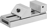
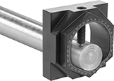
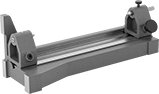
Ultra-Precision Machine Vises
With Flat Jaws
 |
Jaw | Body | Mounting Holes | |||||||||||||||||
|---|---|---|---|---|---|---|---|---|---|---|---|---|---|---|---|---|---|---|---|
Wd. | Ht. | Max. Opening | Material | Texture | Replaceable | Parallel Tolerance | Overall Ht. | Lg. | Material | Base/Bed Parallel Tolerance | Mount Type | Mounting Fasteners Included | No. of | Dia. | Ctr.-to-Ctr. | Each | |||
Fixed Base | |||||||||||||||||||
| 2" | 1" | 3 1/4" | Steel | Smooth, Grooved | Yes | 0.0002" | 2" | 5 7/8" | Steel | 0.0002" | Bolt On | No | 4 | 5/16" | 1" | 5218A52 | 0000000 | ||
| 3" | 1 5/16" | 4 3/4" | Steel | Smooth, Grooved | No | 0.0002" | 2 5/8" | 7 1/2" | Steel | 0.0002" | Bolt On, Clamp On | No | 4 | 5/16" | — | 5218A54 | 00000000 | ||
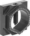
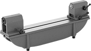
Sine Vises
With Flat Jaws
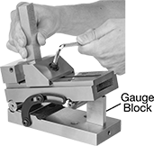 |  |
Shown with Gauge Block (Not Included) |
Jaw | Body | Mounting Holes | ||||||||||||||||||
|---|---|---|---|---|---|---|---|---|---|---|---|---|---|---|---|---|---|---|---|---|
Wd. | Ht. | Max. Opening | Material | Texture | Replaceable | Parallel Tolerance | Overall Ht. | Lg. | Material | Base/Bed Parallel Tolerance | Mount Type | Mounting Fasteners Included | No. of | Dia. | Ctr.-to-Ctr. | Features | Each | |||
Fixed Base | ||||||||||||||||||||
| 3" | 1 5/16" | 4 3/4" | Steel | Grooved | No | 0.0002" | 3 5/8" | 7 1/2" | Steel | 0.0002" | Bolt On | Yes | 4 | 5/16" | 3" | Fixed Dowel Locking Bar Movable Dowel | 6006N11 | 000000000 | ||
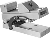
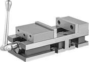
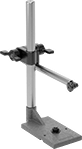
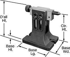
High-Precision Milling-Machine Vises
With Flat Jaws
 |  |
Jaws attached to the outside ends of jaw holders extend the opening |
Vises | Replacement Handles | Repair Kits | ||||||||||||||||||
|---|---|---|---|---|---|---|---|---|---|---|---|---|---|---|---|---|---|---|---|---|
Jaw | Body | |||||||||||||||||||
Wd. | Ht. | Max. Opening | Material | Texture | Replaceable | Max. Extended Opening | Overall Ht. | Lg. | Material | Base/Bed Parallel Tolerance | Mount Type | Mounting Fasteners Included | Each | Each | Each | |||||
Fixed Base | ||||||||||||||||||||
| 4" | 1 1/4" | 6" | Steel | Smooth | Yes | 12 1/4" | 3 5/8" | 12 5/8" | Iron | 0.0005" | Bolt On | No | 8474A18 | 000000000 | 8474A34 | 000000 | 2569N19 | 000000 | ||
| 6" | 1 3/4" | 6" | Steel | Smooth | Yes | 14 3/4" | 4 15/16" | 15 1/16" | Iron | 0.0005" | Bolt On | No | 8474A17 | 00000000 | 8474A35 | 00000 | 2569N13 | 00000 | ||
Precise-Control Pin Vises
With Collet Jaws
Jaw | Overall | ||||||||
|---|---|---|---|---|---|---|---|---|---|
Max. Opening | Material | Texture | Dia. | Lg. | Body Material | Each | |||
Round Jaws | |||||||||
| 0.125" | Steel | Serrated | 3/8" | 3 3/4" | Aluminum | 8455A31 | 000000 | ||
Stationary Clamping Jaw Fixtures
3 Reversible Jaws
 |
Fixtures with three jaws are best for gripping round workpieces.
For Workpiece | Base | Mounting Slots | |||||||||||
|---|---|---|---|---|---|---|---|---|---|---|---|---|---|
OD | ID | Ctr. Through-Hole Dia. | Dia. | Ht. | Dia. | Ht. | Material | No. of | Wd. | Includes | Each | ||
| 5/16" to 6 5/16" (8 to 160 mm) | 1 7/8" to 5 29/32" (48 to 150 mm) | 1 25/32" (45 mm) | 6 11/16" (170 mm) | 1 9/16" (40 mm) | 8 21/32" (220 mm) | 11/16" (18 mm) | Steel | 4 | 1/2" (13 mm) | One Set of Hardened Reversible Jaws, One Chuck Wrench | 7613N11 | 000000000 | |
| 7/16" to 7 7/8" (11 to 200 mm) | 2 7/16" to 7 1/2" (62 to 190 mm) | 2 3/8" (60 mm) | 8 1/4" (210 mm) | 1 25/32" (45 mm) | 10 5/8" (270 mm) | 25/32" (20 mm) | Steel | 4 | 1/2" (13 mm) | One Set of Hardened Reversible Jaws, One Chuck Wrench | 7613N12 | 00000000 | |
| 15/32" to 9 27/32" (12 to 250 mm) | 2 27/32" to 9 7/16" (72 to 240 mm) | 3 5/32" (80 mm) | 10 1/32" (255 mm) | 2 3/32" (53 mm) | 12 13/32" (315 mm) | 25/32" (20 mm) | Steel | 4 | 5/8" (16 mm) | One Set of Hardened Reversible Jaws, One Chuck Wrench | 7613N13 | 00000000 | |
| 19/32" to 11 13/16" (15 to 300 mm) | 3 3/8" to 11 13/32" (86 to 290 mm) | 4 1/8" (105 mm) | 12" (305 mm) | 2 9/32" (58 mm) | 14 9/16" (370 mm) | 7/8" (22 mm) | Steel | 4 | 11/16" (18 mm) | One Set of Hardened Reversible Jaws, One Chuck Wrench | 7613N14 | 00000000 | |
4 Reversible Jaws
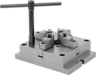 |
Fixtures with four jaws have more holding power than those with three jaws, so they’re often used on square or rectangular workpieces.
For Workpiece | Base | Mounting Slots | |||||||||||||
|---|---|---|---|---|---|---|---|---|---|---|---|---|---|---|---|
OD | ID | Ctr. Through-Hole Dia. | Lg. | Wd. | Ht. | Lg. | Wd. | Ht. | Material | No. of | Wd. | Includes | Each | ||
| 5/32" to 5 1/32" (4 to 128 mm) | 2 5/32" to 5 1/32" (55 to 128 mm) | 1 19/32" (40 mm) | 6 1/2" (165 mm) | 6 1/2" (165 mm) | 1 17/32" (39 mm) | 8 15/32" (215 mm) | 6 1/2" (165 mm) | 11/16" (18 mm) | Steel | 2 | 11/16" (18 mm) | One Set of Hardened Reversible Jaws, One Chuck Wrench | 7613N15 | 000000000 | |
| 3/16" to 6 3/8" (5 to 162 mm) | 2 7/16" to 6 3/8" (62 to 162 mm) | 2 5/32" (55 mm) | 7 7/8" (200 mm) | 7 7/8" (200 mm) | 1 25/32" (45 mm) | 9 27/32" (250 mm) | 7 7/8" (200 mm) | 25/32" (20 mm) | Steel | 2 | 11/16" (18 mm) | One Set of Hardened Reversible Jaws, One Chuck Wrench | 7613N16 | 00000000 | |
| 1/4" to 7 7/8" (6 to 200 mm) | 2 27/32" to 7 7/8" (72 to 200 mm) | 2 3/4" (70 mm) | 9 27/32" (250 mm) | 9 27/32" (250 mm) | 1 31/32" (50 mm) | 12 7/32" (310 mm) | 9 27/32" (250 mm) | 7/8" (22 mm) | Steel | 2 | 11/16" (18 mm) | One Set of Hardened Reversible Jaws, One Chuck Wrench | 7613N17 | 00000000 | |
| 13/32" to 10 7/16" (10 to 265 mm) | 3 9/16" to 10 7/16" (90 to 265 mm) | 3 15/16" (100 mm) | 12 7/32" (310 mm) | 12 7/32" (310 mm) | 2 3/8" (60 mm) | 14 31/32" (380 mm) | 12 7/32" (310 mm) | 1" (25 mm) | Steel | 2 | 7/8" (22 mm) | One Set of Hardened Reversible Jaws, One Chuck Wrench | 7613N18 | 00000000 | |
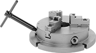
Rotary Angle Indexers
 |  |  |
Indexer with Workpiece Shown in Vise | Indexer with Workpiece |
Cushion-Grip Precise-Control Pin Vises
With Collet Jaws
 |
Jaw | Overall | ||||||||||
|---|---|---|---|---|---|---|---|---|---|---|---|
Max. Opening | Material | Texture | Dia. | Lg. | Body Material | Grip Material | Features | Each | |||
Round Jaws | |||||||||||
| 0.125" | Steel | Smooth | 7/8" | 4 1/4" | Plastic | Rubber | Drill and Tap Storage in Body | 7112A2 | 000000 | ||
Indexing Collet Fixtures
 |  |
1° Index Increments | 15° Index Increments |
Used with a 5C collet (sold separately), these fixtures rotate round, hex, or square workpieces up to 1 1/8" diameter in precise increments. Also known as spindexers or punch formers, they are commonly used to drill holes into cylindrical parts, grind punches into precision shapes, and sharpen drill bits and end mills. To ensure accurate rotation, spindles are precision ground. Mount fixtures to a machine table for horizontal orientation or an angle plate for vertical. A through-hole accommodates long workpieces.
1° Index Increments—Fixtures with 1° index increments have an indexing plate with 36 holes for rotating in 10° steps and 10 additional holes for 1° refinements.
15° Index Increments—Fixtures with 15° index increments have 24 locking positions.
Quarter-Turn Quick-Change Fixture Clamps
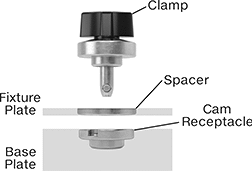 |
Install these clamps into fixture plates, machine subplates, and tombstones to quickly swap components in or out of your machining setup. They lock or unlock with the turn of a knob. Since they locate while they clamp, you can accurately position components with repeatability of ±0.1".
For accurate positioning, use at least two sets of clamps and cam receptacles. Install receptacles into a base plate and clamps into a fixture plate. Line up the two plates, insert the clamps into the receptacles, then turn the knobs to secure your fixture in place. If you need more holding capacity, use additional clamps and receptacles.
Clamps
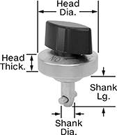 |
For Fixture Plate Thk. | Shank | Head | |||||||||||
|---|---|---|---|---|---|---|---|---|---|---|---|---|---|
Min. | Max. | Dia., mm | Lg. | Material | Dia. | Thk. | Material | Knob Material | Holding Cap., lb. | Each | |||
| 1/8" | 3/8" | 5 | 0.61" | Stainless Steel | 1" | 1/4" | Stainless Steel | Nylon | 10 | 9952N121 | 000000 | ||
| 1/8" | 1/2" | 8 | 0.67" | Stainless Steel | 1 3/8" | 7/16" | Stainless Steel | Nylon | 20 | 9952N126 | 00000 | ||
| 1/2" | 3/4" | 8 | 0.91" | Stainless Steel | 1 3/8" | 7/16" | Stainless Steel | Nylon | 20 | 9952N127 | 00000 | ||
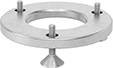
Cam Receptacles
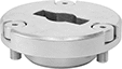 |  |
Fastener Mount | Thread In |
Fastener Mount—Fastener-mount receptacles have three recessed holes on the face so you can secure them to your base plate with the included screws.
Thread In—Thread-in receptacles have a threaded body for installation in a tapped hole. You hold them in place with the included nut, so they’re good for thin base plates.
For Fixture Plate Thk. | |||||||||||
|---|---|---|---|---|---|---|---|---|---|---|---|
Min. | Max. | For Clamp Shank Dia., mm | Dia. | Thk. | Thread Size | Material | Mounting Fasteners Included | Each | |||
Fastener Mount | |||||||||||
| 3/8" | Not Rated | 5 | 1" | 3/8" | — | Nickel-Plated Steel | Yes | 9952N122 | 000000 | ||
| 1/2" | Not Rated | 8 | 1 1/4" | 7/16" | — | Nickel-Plated Steel | Yes | 9952N124 | 00000 | ||
Thread In | |||||||||||
| 1/4" | 3/8" | 5 | 1" | 5/8" | M14 × 1.5 mm | Nickel-Plated Steel | — | 9952N123 | 00000 | ||
| 1/4" | 1/2" | 8 | 1 1/4" | 11/16" | M20 × 1.5 mm | Nickel-Plated Steel | — | 9952N125 | 00000 | ||
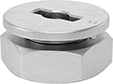
Ball-Lock Quick-Change Fixture Clamps
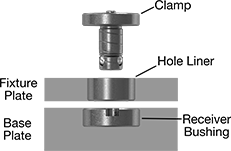 |
Build these components into fixture plates, machine subplates, and tombstones for quick changes. The system clamps and locates at the same time for accurate positioning with repeatability of ±0.0005". Components are compatible with Jergens Ball-Lock, Carr-Lane Carr Lock, and Kurt PinLock quick change systems.
For accurate positioning, at least two sets of clamps, liners, and receivers are required. Install the receivers in the base plate and the liners in the fixture plate. Then line up the two plates, insert the clamps, and tighten their screws to secure the fixture in place. If more holding capacity is needed, use additional clamps and receivers but omit liners to prevent the clamp from getting stuck in the fixture plate.
Clamps
 |
Shank | Head | |||||||||||
|---|---|---|---|---|---|---|---|---|---|---|---|---|
For Fixture Plate Thk. | Dia., mm | Lg. | Dia. | Thk. | Hex Key Size | For Fixture Plate Thk. Tolerance | Holding Cap., lb. | Material | Includes | Each | ||
| 1/2" | 13 | 1.08" | 7/8" | 1/4" | 3/32" | -0.005" to 0.005" | 625 | Black-Oxide Steel | Hex Key Set Screw | 1349N41 | 0000000 | |
| 1/2" | 16 | 1.15" | 1 1/2" | 5/16" | 1/8" | -0.005" to 0.005" | 800 | Black-Oxide Steel | Hex Key Set Screw | 1349N11 | 000000 | |
| 3/4" | 13 | 1.33" | 7/8" | 1/4" | 3/32" | -0.005" to 0.005" | 625 | Black-Oxide Steel | Hex Key Set Screw | 1349N42 | 000000 | |
| 3/4" | 16 | 1.40" | 1 1/2" | 5/16" | 1/8" | -0.005" to 0.005" | 800 | Black-Oxide Steel | Hex Key Set Screw | 1349N43 | 000000 | |
| 3/4" | 20 | 1.53" | 1 3/4" | 3/8" | 1/8" | -0.005" to 0.005" | 2,250 | Black-Oxide Steel | Hex Key Set Screw | 1349N12 | 000000 | |
| 3/4" | 25 | 1.70" | 2" | 3/8" | 5/32" | -0.005" to 0.005" | 5,440 | Black-Oxide Steel | Hex Key Set Screw | 1349N44 | 000000 | |
| 1" | 20 | 1.78" | 1 3/4" | 3/8" | 1/8" | -0.005" to 0.005" | 2,250 | Black-Oxide Steel | Hex Key Set Screw | 1349N45 | 000000 | |
| 1" | 25 | 1.95" | 2" | 3/8" | 5/32" | -0.005" to 0.005" | 5,400 | Black-Oxide Steel | Hex Key Set Screw | 1349N13 | 000000 | |
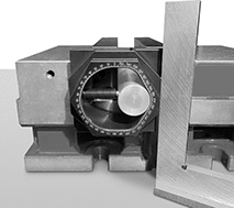
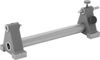
Bench Centers
 |  |
Steel Body Knob Locking | Cast Iron Body Knob Locking |
 | |
Cast Iron Body Lever Locking |
The most accurate bench centers you can find. Our centers help you inspect shafts and other cylindrical parts for the tiniest irregularities that could cause wobbles or vibrations. Machined in the U.S., the head and tailstock are precision ground in pairs for exact alignment between the two centers.
Inserting and removing shafts takes seconds. The tailstock slides and locks them in place with the twist of a handle. Unlike V-blocks, these centers hold shafts by their endpoints to check if they are perfectly centered and round with no runout. If you find wobbles that need more machining, you can pop shafts back into the center to take new measurements without realigning your setup.
Horizontal Orientation—Use horizontal-only centers to inspect heavy parts, such as large crankshafts and drive shafts. With a precision ground base, you don’t need to set them up on a surface plate. They have four adjustable leveling feet to compensate for uneven workbench surfaces.
Vertical Orientation—With accuracy unmatched for their size, these versatile centers check small parts, such as miniature crank shafts. When you need to inspect multiple dimensions, flip them on their end to take measurements in the vertical position.
For Max. Workpiece | Tolerance | Overall | Material | ||||||||||||
|---|---|---|---|---|---|---|---|---|---|---|---|---|---|---|---|
Lg. | Dia. | Orientation | Parallel | Squareness per 6" | Flatness | Lg. | Wd. | Ht. | Center | Body | Locking Style | Wt., lb. | Each | ||
| 8" | 3" | Horizontal, Vertical | -0.0002" to 0.0002" | -0.0003" to 0.0003" | — | 12 1/4" | 3 1/2" | 3 5/8" | Steel | Steel | Knob | 9 | 4338N11 | 000000000 | |
| 12" | 5" | Horizontal, Vertical | -0.0002" to 0.0002" | -0.0003" to 0.0003" | — | 17 5/8" | 5 1/2" | 6 7/8" | Steel | Cast Iron | Knob | 38 | 4338N12 | 00000000 | |
| 18" | 8" | Horizontal | — | — | 0.0005" | 31 1/4" | 5 1/2" | 11 1/2" | Steel | Cast Iron | Lever | 160 | 4338N13 | 00000000 | |
| 36" | 8" | Horizontal | — | — | 0.0010" | 49 1/4" | 5 1/2" | 12" | Steel | Cast Iron | Lever | 240 | 4338N14 | 00000000 | |
 |
Create a setup to inspect identical parts over and over again. These holders fit firmly in the T-slot of horizontal-only centers to keep your indicator in place. They slide and lock anywhere between the head and tailstock to check measurements at any point along your part.
For Max. Workpiece | Base | Upright Post | Arm | ||||||||||
|---|---|---|---|---|---|---|---|---|---|---|---|---|---|
Lg. | Dia. | For Mounting Lug Hole Dia. | Lg. | Wd. | Material | Ht. | Material | Lg. | Material | Each | |||
Lug Mount | |||||||||||||
| 18", 36" | 8" | 7/16" | 7 5/8" | 3 3/4" | Cast Iron | 14" | Steel | 9" | Steel | 4338N15 | 000000000 | ||
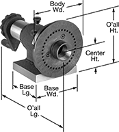
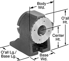
Indexing Jaw-Chuck Fixtures
3 Reversible Jaws
 |
Fixtures with three jaws are best for gripping round workpieces.
Tailstocks—Support long workpieces to improve stability during indexing and machining.
Jaw Fixtures | Tailstocks | |||||||||||||||||||||
|---|---|---|---|---|---|---|---|---|---|---|---|---|---|---|---|---|---|---|---|---|---|---|
For Workpiece | Overall | Base | Tolerance | Mounting Slots | ||||||||||||||||||
OD | ID | Index Increments | Lathe Chuck Dia. | Ctr. Through-Hole Dia. | Ctr. Ht. | Lg. | Wd. | Ht. | Lg. | Wd. | Ht. | Parallel | Squareness | Material | No. of | Wd. | Includes | Each | Each | |||
| 13/32" to 6 5/32" (10 to 155 mm) | 5/32" to 1 21/32" (4 to 42 mm) | 15°, 30°, 45°, 60°, 90°, 120°, 180° | 6" | 1 3/4" | 5" | 9 7/8" | 8 3/4" | 10 7/16" | 8 5/8" | 5 7/8" | 9 1/4" | 0.0002" | 0.0002" | Steel | 5 | 5/8" | One Chuck Wrench | 8565N11 | 000000000 | 8795N12 | 0000000 | |
| 13/32" to 7 3/32" (10 to 180 mm) | 5/32" to 2 7/16" (4 to 62 mm) | 15°, 30°, 45°, 60°, 90°, 120°, 180° | 8" | 2 1/2" | 6 1/4" | 12 1/4" | 9 9/16" | 11 5/8" | 8 7/8" | 6 1/4" | 11 1/4" | 0.0002" | 0.0002" | Steel | 5 | 5/8" | One Chuck Wrench | 8565N12 | 00000000 | 8795N13 | 000000 | |
Tailstocks
 |
Stabilize long workpieces for precise machining. These tailstocks hold your workpiece by its end to keep it straight and aligned. Adjust the center height to use them with a variety of rotary tables, indexing heads, and other fixture setups. Made of cast iron, they resist vibration and wear, so they’ll hold up to heavy duty machining tasks.
Base | Mounting Slot | |||||||||||
|---|---|---|---|---|---|---|---|---|---|---|---|---|
Ctr. Ht. | Lg. | Wd. | Ht. | Overall Ht. | No. of | Wd. | Mounting Fasteners Included | Material | Includes | Each | ||
| 3 1/8" to 4 1/4" | 5 3/8" | 3 3/4" | 3/4" | 5 1/4" | 2 | 5/8" | No | Cast Iron | Standard-Point Dead Center | 8795N11 | 0000000 | |
| 4 1/2" to 6" | 6 1/8" | 4 3/8" | 7/8" | 6 5/8" | 2 | 5/8" | No | Cast Iron | Standard-Point Dead Center | 8795N12 | 000000 | |
| 5 1/8" to 8 1/8" | 7 3/8" | 5 1/2" | 7/8" | 9 1/4" | 2 | 5/8" | No | Cast Iron | Standard-Point Dead Center | 8795N13 | 000000 | |
| 7 1/4" to 10 1/4" | 8 1/8" | 5 3/4" | 1" | 11 1/4" | 2 | 5/8" | No | Cast Iron | Standard-Point Dead Center | 8795N14 | 000000 | |
