


Clear All
Pipe Size Pipe Size | Show |
|---|
Display Type Display Type |
|---|
 | Dial |
Dial Type Dial Type |
|---|
 | Dry |
Connection Style Connection Style |
|---|
 |
| Threaded |
Maximum Pressure, psi Maximum Pressure, psi |
|---|
|
Connection Type Connection Type |
|---|
| Hose | |
For Use With For Use With |
|---|
|
Graduation Marks, kPa Graduation Marks, kPa |
|---|
|
Measures Measures |
|---|
|
Gender Gender |
|---|
|
Connection Location Connection Location |
|---|
| Top | |
Dial Diameter Dial Diameter |
|---|
|
Scale Type Scale Type |
|---|
 | Dual |
Mounting Orientation Mounting Orientation |
|---|
|
Case Material Case Material |
|---|
|
RoHS (Restriction of Hazardous Substances) RoHS (Restriction ofHazardous Substances) |
|---|
|
Environment Environment |
|---|
Connection Material Connection Material |
|---|
|
DFARS (Defense Acquisition Regulations Supplement) DFARS (Defense AcquisitionRegulations Supplement) |
|---|
Maximum Process Temperature Maximum ProcessTemperature |
|---|
|
REACH (Registration, Evaluation, Authorization and Restriction of Chemicals) REACH (Registration,Evaluation, Authorization and Restriction of Chemicals) |
|---|
|
Drinking Water Pressure Gauges
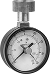
Top Connection
Top Connection
Check the pressure on your drinking water system with these gauges—they meet NSF/ANSI Standard 61 for safe use with potable water. The dry dial on these gauges is best for low-vibration applications, since the needle can bounce if the gauge is shaken. For more accurate readings under heavy vibration, use a liquid-filled gauge. Mount gauges with the dial face upright.
Painted Steel Case with Brass Top Connection—Dual Scale (psi, kPa)
- For Use With: Water
- Accuracy: ±2% Mid Scale (Grade B)
Available Pressure Ranges | |||||
|---|---|---|---|---|---|
Pressure Range | Graduation Marks | Numeric Increments | |||
| psi | kPa | psi | kPa | psi | kPa |
| 0 to 160 | 0 to 1,100 | 2 | 20 | 20 | 200 |
Top Connection | |||||||
|---|---|---|---|---|---|---|---|
| Dial Dia. | Pipe Size | Environment Temp. Range, °F | Process Temp. Range, °F | Environment | Mounting Orientation | Each | |
GHT Female | |||||||
| 2 1/2" | 3/4 | -40° to 150° | -40° to 150° | Food Industry | Upright | 0000000 | 000000 |
Pressure-Regulating Inline Hydraulic Valves
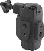
When input pressure varies, use these valves to maintain a consistent pressure. They are often placed after a directional-control valve and before an actuator, such as a cylinder. They have an indicator/gauge port for the inlet and one for the outlet so you can monitor that output pressure remains steady.
![]() For technical drawings and 3-D models, click on a part number.
For technical drawings and 3-D models, click on a part number.
Inlet/Outlet Connection | Relief Connection | O'all | |||||||
|---|---|---|---|---|---|---|---|---|---|
| Pipe Size | Dash Size | Pipe Size | Dash Size | Lg. | Wd. | Ht. | Choose a Set Pressure Range, psi | Each | |
NPT Female Inlet and Relief Port | |||||||||
Cast Iron Body | |||||||||
| 3/4 | 12 | 1/4 | 04 | 5 7/8" | 3 3/4" | 7 1/8" | 000000 | 0000000 | |