


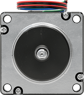
Stepper Motor
with Encoder, NEMA 23, 600.4 in.-oz. Maximum Holding Torque


Component | Motor/Encoders |
Body Shape | Square |
Motor Frame Size | NEMA 23 |
Maximum Holding Torque | 600.4 in·ozf |
Maximum Rotation Speed | 1,300 rpm |
Maximum Current per Phase | 6.5 amp |
Voltage | 5V DC |
Full Step Increment | 1.8° |
Stepper Motor Polarity | Bipolar |
Encoder Positioning Type | Incremental |
Number of Counts per Revolution | 1,000 |
Number of Wire Leads | 4 |
Overall | |
Length | 4.9" |
Width | 2.6" |
Height | 2.3" |
Shaft | |
Diameter | 1/4" |
Length | 3/4" |
Center to Base Length | 1.13" |
Type | D-Profile |
Number of Shafts | 2 |
Temperature Range | |
Minimum | 0° F |
Maximum | 120° F |
Bearing Type | Ball |
Direction of Operation | Clockwise, Counterclockwise |
Duty Cycle | Continuous |
Electrical Connection Type | Hardwire |
Electrical Phase | Two |
Enclosure Material | Aluminum, Steel |
Face Shape | Square |
Inductance per Phase | Not Rated |
Insulation | |
Class | B |
Maximum Temperature | 266° F |
Motor Type | Hybrid Stepper |
Mounting Location | Face |
Mounting Position | Any Angle, Horizontal, Vertical |
Power Source | Electric |
Radial Load Capacity | 15 lb. |
Resistance per Phase | 0.33 ohm |
Rotor Inertia | 3.32 oz·in² |
Thrust Load Capacity | 13 lbf |
Weight | 2.8 lb. |
Wire Connection | Wire Leads |
Wire Lead Color | Black, Blue, Green, Red |
Wire Lead Gauge (AWG) | 18 |
Wire Lead Length | 12" |
Country of Origin | United States |
DFARS Compliance | Specialty Metals COTS-Exempt |
Export Control Classification Number (ECCN) | EAR99 |
REACH Compliance | REACH (EC 1907/2006) (01/17/2023, 233 SVHC) Compliant |
RoHS Compliance | RoHS 3 (2015/863/EU) Compliant |
Schedule B Number | 850131.2000 |
U.S.–Mexico–Canada Agreement (USMCA) Qualifying | No |
Additional Specifications |
To improve positioning accuracy, these stepper motors have a built-in encoder that monitors the real-time speed and position of the shaft. It sends that data to a controller (not included), which adjusts or stops the shaft if it isn’t in the right place. This makes them useful when relative positioning is critical, such as when coordinating motion between two motors. Stepper motors are good for precise, repetitive movements. Similar to the hands of a clock, their shaft turns in small, equal increments for smooth motion. When the shaft stops, it holds its position even when a counteracting force is applied to the load. All are bipolar hybrid stepper motors, so the current can flow in both directions. This helps them deliver higher torque, precision, and efficiency than unipolar stepper motors.
All motors require a controller and drive (not included).
For the Manufacturer User Manual, click on a part number and select Product Detail.
2 Shafts—When relative positioning is critical, such as coordinating motion in a multi-axis system, choose a motor with two shafts and mount an encoder (not included) on one of them. The encoder monitors the position of the shaft and reports back to the controller.
Maximum Holding Torque—Holding torque is the force needed to move the shaft out of position when it is stationary. When the shaft is in motion, torque generally decreases as speed increases. Use a torque-speed curve to confirm which motor will work for your application. Click on a part number and select “Product Detail” to view the curve for a motor.
Full Step Increment—Full step increment is the rotation of the shaft from one position to the next. A smaller full step increment means the rotor has more teeth, producing smoother and more precise motion. 1.8° is considered standard.
The information in this 3-D model is provided for reference only.