


Filter by
Body Thread Size
Energy Capacity
Bumper Material
Thread Size
Body Diameter
Body Material
Extended Length
Return Force
Compressed Length
Rod Material
Maximum Cycles per Minute
Mount Type
Force Mechanism
Compression Force
DFARS Specialty Metals
Export Control Classification Number (ECCN)
Body Finish
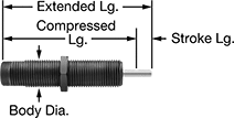
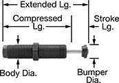
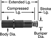
Self-Adjusting Shock Absorbers
Threaded-Body Mount
 |  |
No Bumper | Acetal Bumper |
 |  |
Aluminum Bumper | Urethane Rubber Bumper |
 |
Nylon Bumper |
 |
Steel Bumper |
Body | Rod | Bumper | ||||||||||||||
|---|---|---|---|---|---|---|---|---|---|---|---|---|---|---|---|---|
Energy Cap., in·lbf | Max. Cycles per min., cpm | Stroke Lg. | Extended Lg. | Compressed Lg. | Dia. | Thread Size | Material | Dia. | Material | Dia. | Material | Temp. Range, ° F | Each | |||
| 9 | 33 | 0.2" | 1.22" | 1.02" | 0.24" | M6 × 0.5 mm | Black-Oxide Steel | 0.08" | Stainless Steel | — | — | 32 to 150 | 3692K24 | 000000 | ||
| 11 | 53 | 0.2" | 1.52" | 1.32" | 0.31" | M8 × 0.75 mm | Black-Oxide Steel | 0.08" | Stainless Steel | 0.19" | Acetal | 32 to 150 | 3692K11 | 00000 | ||
| 11 | 53 | 0.2" | 1.52" | 1.32" | 0.31" | M8 × 1 mm | Black-Oxide Steel | 0.08" | Stainless Steel | 0.19" | Acetal | 32 to 150 | 3692K13 | 00000 | ||
| 17 | 70 | 0.24" | 1.97" | 1.73" | 0.31" | M8 × 1 mm | Black-Oxide Steel | 0.08" | Chrome-Plated Steel | 0.26" | Urethane Rubber | 14 to 176 | 6528K511 | 00000 | ||
| 20 | 167 | 0.26" | 2.27" | 2.01" | 0.375" | 3/8"-32 | Black-Oxide Steel | 0.13" | Stainless Steel | 0.3" | Steel | 32 to 150 | 3740K11 | 00000 | ||
| 20 | 167 | 0.26" | 2.27" | 2.01" | 0.39" | M10 × 1 mm | Black-Oxide Steel | 0.13" | Stainless Steel | 0.3" | Steel | 32 to 150 | 3692K15 | 00000 | ||
| 35 | 63 | 0.31" | 2.24" | 1.93" | 0.39" | M10 × 1 mm | Black-Oxide Steel | 0.1" | Chrome-Plated Steel | 0.34" | Urethane Rubber | 14 to 176 | 6528K512 | 00000 | ||
| 44 | 59 | 0.39" | 2.74" | 2.35" | 0.48" | M12 × 1 mm | Black-Oxide Steel | 0.12" | Chrome-Plated Steel | 0.41" | Urethane Rubber | 14 to 176 | 6528K513 | 00000 | ||
| 75 | 56 | 0.4" | 2.76" | 2.36" | 0.48" | M12 × 1 mm | Black-Oxide Steel | 0.13" | Stainless Steel | 0.3" | Steel | 32 to 150 | 3692K16 | 00000 | ||
| 75 | 56 | 0.4" | 2.76" | 2.36" | 0.5" | 1/2"-20 | Black-Oxide Steel | 0.13" | Stainless Steel | 0.3" | Steel | 32 to 150 | 3740K12 | 00000 | ||
| 100 | 10 | 0.25" | 2.75" | 2.5" | 0.55" | M14 × 1.5 mm | Black-Oxide Steel | 0.15" | Stainless Steel | 0.25" | Aluminum | -22 to 140 | 9530K66 | 000000 | ||
| 123 | 41 | 0.5" | 3.66" | 3.16" | 0.55" | M14 × 1 mm | Black-Oxide Steel | 0.19" | Stainless Steel | 0.47" | Nylon | 32 to 150 | 3692K27 | 000000 | ||
| 123 | 41 | 0.5" | 3.66" | 3.16" | 0.563" | 9/16"-18 | Black-Oxide Steel | 0.19" | Stainless Steel | 0.47" | Nylon | 32 to 150 | 3740K19 | 000000 | ||
| 142 | 31 | 0.39" | 3.62" | 3.22" | 0.48" | M12 × 1 mm | Black-Oxide Steel | 0.15" | Stainless Steel | — | — | 32 to 150 | 3740K421 | 000000 | ||
| 175 | 29 | 0.5" | 3.41" | 2.91" | 0.55" | M14 × 1.5 mm | Black-Oxide Steel | 0.19" | Stainless Steel | — | — | 32 to 150 | 3740K412 | 000000 | ||
| 175 | 34 | 0.5" | 3.41" | 2.91" | 0.55" | M14 × 1.5 mm | Black-Oxide Steel | 0.19" | Stainless Steel | — | — | 32 to 150 | 3740K411 | 000000 | ||
| 200 | 10 | 0.5" | 3.75" | 3.25" | 0.78" | M20 × 1.5 mm | Black-Oxide Steel | 0.15" | Stainless Steel | 0.25" | Aluminum | -22 to 140 | 9530K67 | 000000 | ||
| 225 | 22 | 0.63" | 4.5" | 3.87" | 0.55" | M14 × 1.5 mm | Black-Oxide Steel | 0.16" | Stainless Steel | 0.47" | Steel | 32 to 150 | 3692K19 | 00000 | ||
| 225 | 22 | 0.63" | 4.5" | 3.87" | 0.563" | 9/16"-18 | Black-Oxide Steel | 0.16" | Stainless Steel | 0.47" | Steel | 32 to 150 | 3740K15 | 000000 | ||
| 250 | 26 | 1" | 4.75" | 3.75" | 0.98" | M25 × 1.5 mm | Black-Oxide Steel | 0.19" | Stainless Steel | 0.38" | Aluminum | -22 to 140 | 9530K68 | 000000 | ||
| 274 | 27 | 0.47" | 3.7" | 3.22" | 0.55" | M14 × 1.5 mm | Black-Oxide Steel | 0.19" | Stainless Steel | — | — | 32 to 150 | 3740K415 | 000000 | ||
| 288 | 23 | 0.5" | 4.07" | 3.57" | 0.75" | 3/4"-16 | Black-Oxide Steel | 0.25" | Stainless Steel | 0.66" | Nylon | 32 to 150 | 3740K21 | 000000 | ||
| 288 | 23 | 0.5" | 4.07" | 3.57" | 0.78" | M20 × 1.5 mm | Black-Oxide Steel | 0.25" | Stainless Steel | 0.66" | Nylon | 32 to 150 | 3692K28 | 000000 | ||
| 300 | 22 | 0.75" | 4.62" | 3.87" | 0.75" | 3/4"-16 | Black-Oxide Steel | 0.19" | Stainless Steel | 0.66" | Steel | 32 to 150 | 3740K16 | 000000 | ||
| 300 | 22 | 0.75" | 4.62" | 3.87" | 0.78" | M20 × 1.5 mm | Black-Oxide Steel | 0.19" | Stainless Steel | 0.66" | Steel | 32 to 150 | 3692K21 | 00000 | ||
| 360 | 19 | 0.5" | 3.81" | 3.31" | 0.75" | 3/4"-16 | Black-Oxide Steel | 0.25" | Stainless Steel | — | — | 32 to 150 | 3740K413 | 000000 | ||
| 360 | 19 | 0.5" | 3.81" | 3.31" | 0.78" | M20 × 1.5 mm | Black-Oxide Steel | 0.25" | Stainless Steel | — | — | 32 to 150 | 3740K414 | 000000 | ||
| 600 | 17 | 1" | 5.76" | 4.76" | 0.98" | M25 × 1.5 mm | Black-Oxide Steel | 0.31" | Stainless Steel | 0.9" | Nylon | 32 to 150 | 3692K29 | 000000 | ||
| 600 | 17 | 1" | 5.76" | 4.76" | 1" | 1"-12 | Black-Oxide Steel | 0.31" | Stainless Steel | 0.9" | Nylon | 32 to 150 | 3740K22 | 000000 | ||
| 620 | 11 | 0.59" | 4.15" | 3.56" | 0.75" | 3/4"-16 | Black-Oxide Steel | 0.25" | Stainless Steel | 0.66" | Steel | 32 to 150 | 3740K1 | 000000 | ||
| 650 | 10 | 0.59" | 4.15" | 3.56" | 0.75" | 3/4"-16 | Black-Oxide Steel | 0.25" | Stainless Steel | 0.66" | Steel | 32 to 150 | 3740K418 | 000000 | ||
| 650 | 10 | 1" | 4.75" | 3.75" | 0.98" | M25 × 1.5 mm | Black-Oxide Steel | 0.19" | Stainless Steel | 0.38" | Aluminum | -22 to 140 | 9530K71 | 000000 | ||
| 650 | 15 | 1" | 5.62" | 4.62" | 0.98" | M25 × 1.5 mm | Black-Oxide Steel | 0.25" | Stainless Steel | 0.9" | Steel | 32 to 150 | 3692K23 | 000000 | ||
| 650 | 15 | 1" | 5.62" | 4.62" | 1" | 1"-12 | Black-Oxide Steel | 0.25" | Stainless Steel | 0.9" | Steel | 32 to 150 | 3740K18 | 000000 | ||
| 690 | 15 | 1" | 5.93" | 4.93" | 1.06" | M27 × 3 mm | Black-Oxide Steel | 0.31" | Chrome-Plated Steel | 0.89" | Urethane Rubber | 14 to 176 | 6528K514 | 000000 | ||
| 975 | 14 | 1.58" | 7.44" | 5.86" | 1" | 1"-12 | Black-Oxide Steel | 0.25" | Stainless Steel | 0.9" | Steel | 32 to 150 | 3740K3 | 000000 | ||
| 1,860 | 5 | 0.91" | 5.51" | 4.6" | 0.98" | M25 × 1.5 mm | Black-Oxide Steel | 0.38" | Stainless Steel | 0.9" | Steel | 32 to 150 | 3740K419 | 000000 | ||
| 1,860 | 5 | 0.91" | 5.51" | 4.6" | 1" | 1"-12 | Black-Oxide Steel | 0.38" | Stainless Steel | 0.9" | Steel | 32 to 150 | 3740K2 | 000000 | ||
| 2,000 | 10 | 1" | 5.25" | 4.25" | 1.3" | M33 × 1.5 mm | Black-Oxide Steel | 0.28" | Stainless Steel | 0.5" | Aluminum | -22 to 140 | 9530K72 | 000000 | ||
| 5,000 | 10 | 2" | 8.25" | 6.25" | 1.375" | 1 3/8"-12 | Black-Oxide Steel | 0.34" | Stainless Steel | 0.63" | Aluminum | -22 to 140 | 9530K54 | 000000 | ||
| 5,000 | 10 | 2" | 8.25" | 6.25" | 1.42" | M36 × 1.5 mm | Black-Oxide Steel | 0.34" | Stainless Steel | 0.63" | Aluminum | -22 to 140 | 9530K74 | 000000 | ||
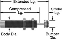
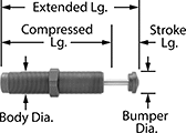
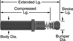
Adjustable Shock Absorbers
Threaded-Body Mount
 |
Threaded-body mount shock absorbers use Mounting Blocks for Shock Absorbers (not included) for mounting. They include mounting nuts.
Nylon Bumper—Nylon bumpers are nonmarring.
Urethane Rubber Bumper—Urethane rubber bumpers are nonmarring.
Body | Rod | Bumper | ||||||||||||||
|---|---|---|---|---|---|---|---|---|---|---|---|---|---|---|---|---|
Energy Cap., in·lbf | Max. Cycles per min., cpm | Stroke Lg. | Extended Lg. | Compressed Lg. | Dia. | Thread Size | Material | Dia. | Material | Dia. | Material | Temp. Range, ° F | Each | |||
Variable Adjustment | ||||||||||||||||
| 35 | 25 | 0.4" | 3.31" | 2.91" | 0.42" | M12 × 1 mm | Black-Oxide Steel | 0.13" | Stainless Steel | 0.3" | Steel | 32 to 150 | 3691K11 | 000000 | ||
| 35 | 25 | 0.4" | 3.31" | 2.91" | 0.5" | 1/2"-20 | Black-Oxide Steel | 0.13" | Stainless Steel | 0.3" | Steel | 32 to 150 | 3742K11 | 00000 | ||
| 200 | 25 | 0.5" | 3.67" | 3.17" | 0.46" | M14 × 1.5 mm | Black-Oxide Steel | 0.19" | Stainless Steel | 0.47" | Nylon | 32 to 150 | 3691K12 | 000000 | ||
| 200 | 25 | 0.5" | 3.67" | 3.17" | 0.563" | 9/16"-18 | Black-Oxide Steel | 0.19" | Stainless Steel | 0.47" | Nylon | 32 to 150 | 3742K12 | 000000 | ||
| 275 | 18 | 0.5" | 4.35" | 3.85" | 0.75" | 3/4"-16 | Anodized Aluminum | 0.19" | Nickel-Plated Steel | 0.5" | Urethane Rubber | 32 to 150 | 3742K27 | 000000 | ||
| 275 | 18 | 0.5" | 4.35" | 3.85" | 0.75" | M20 × 1.5 mm | Anodized Aluminum | 0.19" | Nickel-Plated Steel | 0.5" | Urethane Rubber | 32 to 150 | 3691K24 | 000000 | ||
| 300 | 22 | 0.75" | 4.67" | 3.92" | 0.75" | 3/4"-16 | Black-Oxide Steel | 0.19" | Stainless Steel | 0.66" | Steel | 32 to 150 | 3742K19 | 000000 | ||
| 300 | 22 | 0.75" | 4.67" | 3.92" | 0.75" | M20 × 1.5 mm | Black-Oxide Steel | 0.19" | Stainless Steel | 0.66" | Steel | 32 to 150 | 3691K21 | 000000 | ||
| 600 | 17 | 1" | 5.6" | 4.6" | 1" | 1"-12 | Black-Oxide Steel | 0.25" | Stainless Steel | 0.9" | Steel | 32 to 150 | 3742K21 | 000000 | ||
| 600 | 17 | 1" | 5.62" | 4.62" | 1" | M25 × 1.5 mm | Black-Oxide Steel | 0.25" | Stainless Steel | 0.9" | Steel | 32 to 150 | 3691K22 | 000000 | ||
| 715 | 15 | 1" | 5.62" | 4.62" | 1" | 1"-12 | Anodized Aluminum | 0.25" | Chrome-Plated Steel | 0.62" | Urethane Rubber | 32 to 150 | 3742K28 | 000000 | ||
| 715 | 15 | 1" | 5.62" | 4.62" | 1" | M27 × 3 mm | Anodized Aluminum | 0.25" | Chrome-Plated Steel | 0.62" | Urethane Rubber | 32 to 150 | 3691K25 | 000000 | ||
| 1,500 | 7 | 0.91" | 5.44" | 4.53" | 1.15" | M33 × 1.5 mm | Black-Oxide Steel | 0.375" | Chrome-Plated Steel | 1" | Steel | 32 to 150 | 3691K15 | 000000 | ||
| 1,500 | 7 | 0.91" | 5.44" | 4.53" | 1.25" | 1 1/4"-12 | Black-Oxide Steel | 0.375" | Chrome-Plated Steel | 1" | Steel | 32 to 150 | 3742K15 | 000000 | ||
| 3,450 | 5 | 0.91" | 5.69" | 4.78" | 1.65" | M45 × 1.5 mm | Black-Oxide Steel | 0.5" | Chrome-Plated Steel | 1.38" | Steel | 32 to 150 | 3691K16 | 000000 | ||
| 3,450 | 5 | 0.91" | 5.69" | 4.78" | 1.75" | 1 3/4"-12 | Black-Oxide Steel | 0.5" | Chrome-Plated Steel | 1.38" | Steel | 32 to 150 | 3742K16 | 000000 | ||
| 6,900 | 2 | 1.91" | 7.69" | 5.78" | 1.65" | M45 × 1.5 mm | Black-Oxide Steel | 0.5" | Chrome-Plated Steel | 1.38" | Steel | 32 to 150 | 3691K17 | 000000 | ||
| 6,900 | 2 | 1.91" | 7.69" | 5.78" | 1.75" | 1 3/4"-12 | Black-Oxide Steel | 0.5" | Chrome-Plated Steel | 1.38" | Steel | 32 to 150 | 3742K17 | 000000 | ||
| 10,350 | 2 | 2.91" | 9.69" | 6.78" | 1.75" | 1 3/4"-12 | Black-Oxide Steel | 0.5" | Chrome-Plated Steel | 1.38" | Steel | 32 to 150 | 3742K18 | 000000 | ||
| 11,506 | 2 | 2.91" | 9.69" | 6.78" | 1.75" | M45 × 1.5 mm | Black-Oxide Steel | 0.5" | Chrome-Plated Steel | 1.38" | Steel | 32 to 150 | 3691K23 | 000000 | ||
Flange Mount
 |
Flange-mount shock absorbers can be attached anywhere along the body. Secure them in place with the included locknut.
Urethane Rubber Bumper—Urethane rubber bumpers are nonmarring.
Body | Rod | Bumper | Flange | |||||||||||||||||
|---|---|---|---|---|---|---|---|---|---|---|---|---|---|---|---|---|---|---|---|---|
Energy Cap., in·lbf | Max. Cycles per min., cpm | Stroke Lg. | Extended Lg. | Compressed Lg. | Dia. | Material | Dia. | Material | Dia. | Material | Wd. | Ht. | Mounting Hole Ctr.-to-Ctr. | Mounting Hole Dia. | Thk. | Temp. Range, ° F | Each | |||
Variable Adjustment | ||||||||||||||||||||
| 3,800 | 3 | 1.91" | 7.44" | 5.53" | 1.25" | Steel | 1.25" | Chrome-Plated Steel | 1" | Urethane Rubber | 2" | 1 1/2" | 1.62" | 0.22" | 3/8" | 10 to 150 | 6518K83 | 0000000 | ||
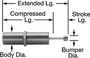
Corrosion-Resistant Self-Adjusting Shock Absorbers
Threaded-Body Mount
 |
Body | Rod | Bumper | ||||||||||||||
|---|---|---|---|---|---|---|---|---|---|---|---|---|---|---|---|---|
Energy Cap., in·lbf | Max. Cycles per min., cpm | Stroke Lg. | Extended Lg. | Compressed Lg. | Dia. | Thread Size | Material | Dia. | Material | Dia. | Material | Temp. Range, ° F | Each | |||
| 100 | 10 | 0.25" | 2.75" | 2.5" | 0.56" | 9/16"-18 | Stainless Steel | 0.15" | Stainless Steel | 0.25" | Stainless Steel | -20 to 140 | 9553K1 | 0000000 | ||
| 200 | 10 | 0.5" | 3.75" | 3.25" | 0.75" | 3/4"-16 | Stainless Steel | 0.15" | Stainless Steel | 0.25" | Stainless Steel | -20 to 140 | 9553K2 | 000000 | ||
| 250 | 27 | 1" | 4.75" | 3.75" | 1" | 1"-12 | Stainless Steel | 0.19" | Stainless Steel | 0.38" | Stainless Steel | -20 to 140 | 9553K3 | 000000 | ||
| 650 | 10 | 1" | 4.75" | 3.75" | 1" | 1"-12 | Stainless Steel | 0.19" | Stainless Steel | 0.38" | Stainless Steel | -20 to 140 | 9553K4 | 000000 | ||
| 2,000 | 10 | 1" | 5.25" | 4.25" | 1.25" | 1 1/4"-12 | Stainless Steel | 0.28" | Stainless Steel | 0.5" | Stainless Steel | -20 to 140 | 9553K5 | 000000 | ||
| 5,000 | 10 | 2" | 8.25" | 6.25" | 1.38" | 1 3/8"-12 | Stainless Steel | 0.34" | Stainless Steel | 0.63" | Stainless Steel | -20 to 140 | 9553K7 | 000000 | ||
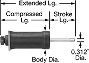
Light Duty Adjustable Shock Absorbers
Through-Wall Mount
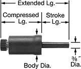 |
Through-wall shock absorbers have a stud and nut under the removable knob for mounting through a panel or bracket.
Body | Rod | Mounting Stud | |||||||||||||
|---|---|---|---|---|---|---|---|---|---|---|---|---|---|---|---|
Energy Cap., in·lbf | Max. Cycles per min., cpm | Stroke Lg. | Extended Lg. | Compressed Lg. | Dia. | Material | Dia. | Material | Thread Size | Lg. | Temp. Range, ° F | Each | |||
Variable Adjustment | |||||||||||||||
| 4 | 600 | 1.1" | 4.32" | 2.99" | 1.01" | Rubber-Coated Borosilicate Glass | 0.375" | Urethane Rubber | 3/8"-32 | 1/8" | -67 to 158 | 6430K31 | 000000 | ||
| 9 | 330 | 1.3" | 4.15" | 2.62" | 1.35" | Rubber-Coated Borosilicate Glass | 0.375" | Urethane Rubber | 3/8"-32 | 1/8" | -67 to 158 | 6430K32 | 00000 | ||
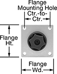
Flange Mount
 |  |
Body | Rod | Flange | ||||||||||||||||||
|---|---|---|---|---|---|---|---|---|---|---|---|---|---|---|---|---|---|---|---|---|
Energy Cap., in·lbf | Max. Cycles per min., cpm | Stroke Lg. | Extended Lg. | Compressed Lg. | Dia. | Material | Dia. | Material | Tip Material | Location | Wd. | Ht. | Mounting Hole Ctr.-to-Ctr. | Mounting Hole Dia. | Thk. | Temp. Range, ° F | Each | |||
Variable Adjustment | ||||||||||||||||||||
| 36 | 200 | 2.3" | 6.7" | 3.9" | 1.74" | Rubber-Coated Borosilicate Glass | 0.312" | Acetal | Urethane Rubber | Back | 1 3/4" | 1 3/4" | 1.38" | 0.171" | 1/8" | -67 to 158 | 6430K33 | 0000000 | ||
| 84 | 70 | 2.3" | 6.7" | 3.9" | 2.21" | Rubber-Coated Borosilicate Glass | 0.312" | Acetal | Urethane Rubber | Back | 2 1/8" | 2 1/8" | 1 3/4" | 0.171" | 1/8" | -67 to 158 | 6430K34 | 000000 | ||
Adjustable Air Springs
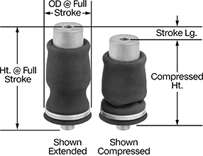
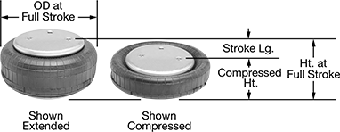
Miniature-Sleeve Air Spring
 |
Air Inlet | Mount. Hole | Mount. Stud | ||||||||||||||||
|---|---|---|---|---|---|---|---|---|---|---|---|---|---|---|---|---|---|---|
Ht. @ Full Stroke | Compressed Ht. | Stroke Lg. | Extended Ht. | Full Stroke Lifting Force @ Pressure | Beginning Stroke Lifting Force @ Pressure | OD @ Full Stroke | Temp. Range, ° F | Air Spring Material | Thread Type | Gender | Pipe Size | Thread Size | Dp. | Thread Size | Lg. | Each | ||
| 4.6" | 1.5" | 2.1" | 3.6" | 10 lbf @ 20 psi 40 lbf @ 60 psi 120 lbf @ 100 psi | 120 lbf @ 20 psi 360 lbf @ 60 psi 600 lbf @ 100 psi | 3.6" | -20 to 135 | Neoprene | NPTF | Female | 1/8 | 5/16"-18 | 7/16" | 5/8"-11 | 1" | 9538K21 | 000000 | |
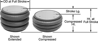
Sleeve Air Spring
 |
Air Inlet | Mount. Hole | Mount. Stud | ||||||||||||||||
|---|---|---|---|---|---|---|---|---|---|---|---|---|---|---|---|---|---|---|
Ht. @ Full Stroke | Compressed Ht. | Stroke Lg. | Extended Ht. | Full Stroke Lifting Force @ Pressure | Beginning Stroke Lifting Force @ Pressure | OD @ Full Stroke | Temp. Range, ° F | Air Spring Material | Thread Type | Gender | Pipe Size | Thread Size | Dp. | Thread Size | Lg. | Each | ||
| 6.88" | 2.2" | 4" | 6.25" | 140 lbf @ 20 psi 320 lbf @ 60 psi 560 lbf @ 100 psi | 250 lbf @ 20 psi 700 lbf @ 60 psi 1,250 lbf @ 100 psi | 5.6" | -20 to 135 | Neoprene | NPTF | Female | 1/8 | 3/8"-16 | 1/2" | 3/4"-16 | 0.63" | 9538K22 | 0000000 | |
| 7.73" | 2.2" | 4.9" | 7.1" | 80 lbf @ 20 psi 180 lbf @ 60 psi 310 lbf @ 100 psi | 340 lbf @ 20 psi 700 lbf @ 60 psi 1,100 lbf @ 100 psi | 4.6" | -20 to 135 | Neoprene | NPTF | Female | 1/8 | 3/8"-16 | 1/2" | 3/4"-16 | 0.63" | 9538K24 | 00000 | |
| 8.72" | 3.6" | 4.4" | 8" | 40 lbf @ 20 psi 60 lbf @ 60 psi 110 lbf @ 100 psi | 60 lbf @ 20 psi 200 lbf @ 60 psi 360 lbf @ 100 psi | 3.25" | -20 to 135 | Neoprene | NPTF | Female | 1/8 | 1/2"-13 | 5/8" | 3/4"-16 | 0.72" | 9538K23 | 00000 | |
| 10.21" | 4" | 5.5" | 9.5" | 160 lbf @ 20 psi 500 lbf @ 60 psi 800 lbf @ 100 psi | 190 lbf @ 20 psi 540 lbf @ 60 psi 950 lbf @ 100 psi | 5.7" | -20 to 135 | Neoprene | NPTF | Female | 1/8 | 1/2"-13 | 5/8" | 3/4"-16 | 0.71" | 9538K28 | 00000 | |
| 11.21" | 4" | 6.5" | 10.5" | 140 lbf @ 20 psi 340 lbf @ 60 psi 540 lbf @ 100 psi | 170 lbf @ 20 psi 520 lbf @ 60 psi 850 lbf @ 100 psi | 4.6" | -20 to 135 | Neoprene | NPTF | Female | 1/8 | 1/2"-13 | 5/8" | 3/4"-16 | 0.71" | 9538K25 | 00000 | |
| 11.21" | 4" | 6.5" | 10.5" | 180 lbf @ 20 psi 460 lbf @ 60 psi 750 lbf @ 100 psi | 230 lbf @ 20 psi 660 lbf @ 60 psi 1,100 lbf @ 100 psi | 5.6" | -20 to 135 | Neoprene | NPTF | Female | 1/8 | 1/2"-13 | 5/8" | 3/4"-16 | 0.71" | 9538K26 | 00000 | |
| 12" | 4.1" | 6.8" | 10.9" | 240 lbf @ 20 psi 700 lbf @ 60 psi 1,200 lbf @ 100 psi | 420 lbf @ 20 psi 1,100 lbf @ 60 psi 2,000 lbf @ 100 psi | 7" | -20 to 135 | Neoprene | NPTF | Female | 1/8 | — | — | — | — | 9538K27 | 000000 | |
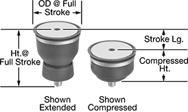
Single-Tire Air Spring
 |
Air Inlet | Mount. Hole | ||||||||||||||||
|---|---|---|---|---|---|---|---|---|---|---|---|---|---|---|---|---|---|
Ht. @ Full Stroke | Compressed Ht. | Stroke Lg. | Extended Ht. | Full Stroke Lifting Force @ Pressure | Beginning Stroke Lifting Force @ Pressure | OD @ Full Stroke | Temp. Range, ° F | Air Spring Material | Thread Type | Gender | Pipe Size | Ctr.-to-Ctr. | Thread Size | Dp. | Each | ||
| 3.8" | 1.8" | 2" | 3.8" | 60 lbf @ 20 psi 280 lbf @ 60 psi 560 lbf @ 100 psi | 280 lbf @ 20 psi 900 lbf @ 60 psi 1,500 lbf @ 100 psi | 5.7" | -20 to 135 | Neoprene | NPTF | Female | 1/4 | 1 3/4" | 3/8"-16 | 5/8" | 9539K41 | 000000 | |
| 4.8" | 1.8" | 3" | 4.8" | 30 lbf @ 20 psi 260 lbf @ 60 psi 520 lbf @ 100 psi | 320 lbf @ 20 psi 950 lbf @ 60 psi 1,600 lbf @ 100 psi | 6" | -20 to 135 | Neoprene | NPTF | Female | 1/4 | 1 3/4" | 3/8"-16 | 5/8" | 9539K43 | 000000 | |
| 4.8" | 2" | 2.8" | 4.8" | 60 lbf @ 20 psi 440 lbf @ 60 psi 850 lbf @ 100 psi | 420 lbf @ 20 psi 1,200 lbf @ 60 psi 2,000 lbf @ 100 psi | 6.5" | -20 to 135 | Neoprene | NPTF | Female | 1/4 | 1 3/4" | 3/8"-16 | 5/8" | 9539K44 | 000000 | |
| 5.2" | 2" | 3.2" | 5.2" | 100 lbf @ 20 psi 350 lbf @ 60 psi 850 lbf @ 100 psi | 500 lbf @ 20 psi 1,500 lbf @ 60 psi 2,600 lbf @ 100 psi | 7.7" | -20 to 135 | Neoprene | NPTF | Female | 1/4 | 1 3/4" | 3/8"-16 | 5/8" | 9539K46 | 000000 | |
| 5.2" | 3.2" | 2" | 5.9" | 280 lbf @ 20 psi 850 lbf @ 60 psi 1,500 lbf @ 100 psi | 900 lbf @ 20 psi 2,900 lbf @ 60 psi 4,900 lbf @ 100 psi | 11" | -56 to 135 | Natural Rubber | NPTF | Female | 1/4 | 3 1/2" | 3/8"-16 | 5/8" | 9539K42 | 000000 | |
| 5.3" | 2" | 3.3" | 5.3" | 100 lbf @ 20 psi 550 lbf @ 60 psi 1,100 lbf @ 100 psi | 660 lbf @ 20 psi 2,100 lbf @ 60 psi 3,600 lbf @ 100 psi | 8.7" | -20 to 135 | Neoprene | NPTF | Female | 1/4 | 2 3/4" | 3/8"-16 | 5/8" | 9539K47 | 000000 | |
| 5.3" | 2.3" | 3" | 5.9" | 280 lbf @ 20 psi 850 lbf @ 60 psi 1,500 lbf @ 100 psi | 1,100 lbf @ 20 psi 3,300 lbf @ 60 psi 5,600 lbf @ 100 psi | 11" | -56 to 135 | Natural Rubber | NPTF | Female | 1/4 | 3 1/2" | 3/8"-16 | 5/8" | 9539K55 | 000000 | |
| 5.4" | 2" | 3.4" | 7.1" | 10 lbf @ 20 psi 300 lbf @ 60 psi 750 lbf @ 100 psi | 750 lbf @ 20 psi 1,800 lbf @ 60 psi 3,000 lbf @ 100 psi | 7" | -20 to 135 | Neoprene | NPTF | Female | 1/4 | 1 3/4" | 3/8"-16 | 5/8" | 9539K49 | 000000 | |
| 5.6" | 2.6" | 3" | 7.2" | 440 lbf @ 20 psi 1,800 lbf @ 60 psi 3,600 lbf @ 100 psi | 1,700 lbf @ 20 psi 5,100 lbf @ 60 psi 8,800 lbf @ 100 psi | 13.2" | -56 to 135 | Natural Rubber | NPTF | Female | 1/4 | 6.2" | 3/8"-16 | 5/8" | 9539K48 | 000000 | |
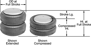
Double-Tire Air Spring
 |
Air Inlet | Mount. Hole | Mount. Stud | |||||||||||||||||
|---|---|---|---|---|---|---|---|---|---|---|---|---|---|---|---|---|---|---|---|
Ht. @ Full Stroke | Compressed Ht. | Stroke Lg. | Extended Ht. | Full Stroke Lifting Force @ Pressure | Beginning Stroke Lifting Force @ Pressure | OD @ Full Stroke | Temp. Range, ° F | Air Spring Material | Thread Type | Gender | Pipe Size | Ctr.-to-Ctr. | Thread Size | Dp. | Thread Size | Lg. | Each | ||
| 7.1" | 2.8" | 4.3" | 7.7" | 0 lbf @ 20 psi 220 lbf @ 60 psi 580 lbf @ 100 psi | 750 lbf @ 20 psi 1,700 lbf @ 60 psi 2,800 lbf @ 100 psi | 6.5" | -20 to 135 | Neoprene | NPTF | Female | 1/4 | 1 3/4" | 3/8"-16 | 5/8" | — | — | 9551K51 | 0000000 | |
| 9 1/2" | 2.9" | 6.6" | 10.1" | 30 lbf @ 20 psi 450 lbf @ 60 psi 1,000 lbf @ 100 psi | 1,200 lbf @ 20 psi 3,100 lbf @ 60 psi 5,000 lbf @ 100 psi | 8.8" | -20 to 135 | Neoprene | NPTF | Female | 1/4 | 2 3/4" | 3/8"-16 | 5/8" | — | — | 9551K54 | 000000 | |
| 9 1/2" | 3.2" | 6.3" | 10.8" | 20 lbf @ 20 psi 400 lbf @ 60 psi 1,100 lbf @ 100 psi | 1,000 lbf @ 20 psi 3,300 lbf @ 60 psi 5,700 lbf @ 100 psi | 10.3" | -56 to 135 | Natural Rubber | NPTF | Female | 1/4 | 3 1/2" | 3/8"-16 | 5/8" | — | — | 9551K52 | 000000 | |
| 9 1/2" | 3.4" | 6.1" | 11.1" | 240 lbf @ 20 psi 1,200 lbf @ 60 psi 2,700 lbf @ 100 psi | 1,600 lbf @ 20 psi 5,500 lbf @ 60 psi 9,400 lbf @ 100 psi | 13" | -56 to 135 | Natural Rubber | NPTF | Female | 1/4 | 6.2" | 3/8"-16 | 5/8" | — | — | 9551K53 | 000000 | |
| 10.7" | 3.5" | 7.2" | 12.2" | 120 lbf @ 20 psi 800 lbf @ 60 psi 1,500 lbf @ 100 psi | 1,250 lbf @ 20 psi 3,600 lbf @ 60 psi 6,000 lbf @ 100 psi | 10.3" | -56 to 135 | Natural Rubber | NPTF | Female | 1/4 | 3 1/2" | 3/8"-16 | 5/8" | 1/2"-13 | 1.2" | 9551K55 | 000000 | |
| 12.7" | 4.3" | 8.4" | 14.4" | 70 lbf @ 20 psi 1,150 lbf @ 60 psi 2,600 lbf @ 100 psi | 1,800 lbf @ 20 psi 5,800 lbf @ 60 psi 10,000 lbf @ 100 psi | 13.7" | -56 to 135 | Natural Rubber | NPTF | Female | 1/4 | 6.2" | 3/8"-16 | 5/8" | — | — | 9551K56 | 000000 | |
Triple-Tire Air Spring
 |
Air Inlet | Mount. Hole | ||||||||||||||||
|---|---|---|---|---|---|---|---|---|---|---|---|---|---|---|---|---|---|
Ht. @ Full Stroke | Compressed Ht. | Stroke Lg. | Extended Ht. | Full Stroke Lifting Force @ Pressure | Beginning Stroke Lifting Force @ Pressure | OD @ Full Stroke | Temp. Range, ° F | Air Spring Material | Thread Type | Gender | Pipe Size | Ctr.-to-Ctr. | Thread Size | Dp. | Each | ||
| 15.2" | 5" | 10.2" | 18" | 80 lbf @ 20 psi 1,900 lbf @ 60 psi 4,700 lbf @ 100 psi | 2,600 lbf @ 20 psi 8,100 lbf @ 60 psi 15,000 lbf @ 100 psi | 15.5" | -56 to 135 | Natural Rubber | NPTF | Female | 1/4 | 6 1/4" | 3/8"-16 | 5/8" | 9551K57 | 0000000 | |
