How to Identify and Measure Fittings
Pipe size is an industry designation, not the actual size. View information about how to measure threaded and unthreaded pipe and pipe fittings.
More
About On/Off Valves
More
High-Pressure Nipples for Compressed Gas
Commonly used in high-pressure welding applications, these nipples connect your tank to the inlet of a pressure regulator. One side has a threaded pipe end and the other side is designed to sit inside a threaded nut (sold separately) so you can make a threaded connection.
Brass nipples have good corrosion resistance and are softer than 316 stainless steel nipples, so they're easier to thread together. Chrome-plated brass nipples have better corrosion and wear resistance than unplated brass nipples and have a bright, shiny appearance.
Nipples that tighten by hand should be paired with a nut with a plastic grip.

- Maximum Pressure: See table
- Maximum Temperature: 120° F
Regulator Connection | ||||||
|---|---|---|---|---|---|---|
| For Number (Max. Pressure) | Pipe Size | Thread Type | Lg. | For Use With | Each | |
Brass—Tighten With Wrench | ||||||
| CGA 660 (3,000 psi @ 72° F) | 1/4 | NPT | 1 3/4" | Refrigerant Gases | 000000000 | 000000 |
Brass—Tighten By Hand | ||||||
| CGA 660 (3,000 psi @ 72° F) | 1/4 | NPT | 1 3/4" | Refrigerant Gases | 0000000 | 00000 |
Chrome-Plated Brass—Tighten With Wrench | ||||||
| CGA 660 (3,000 psi @ 72° F) | 1/4 | NPT | 1 3/4" | Refrigerant Gases | 0000000 | 00000 |

- Maximum Pressure: See table
- Maximum Temperature: 120° F
Refrigerant Hose Fittings

- Maximum Pressure: 500 psi @ 72° F
- Maximum Vacuum: 28 in. of Hg @ 72° F
- Temperature Range: -40° to 280° F
- Compatible With: Danfoss EZ Clip
- All Fittings Swivel Until Tightened
- Specifications Met: SAE J2064, SAE J3062
- Compatible Hose: Refrigerant Hose
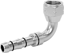
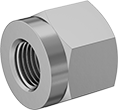
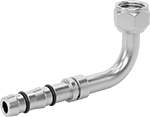
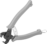
No need for expensive crimping tools—these fittings make air conditioning and refrigeration assemblies with clamps. Instead of a crimper, they use two clamps that you tighten against a cage on your fitting with pliers. Both fitting ends swivel until tightened, so you don't have to rotate the entire hose during installation. The cage and clamps stretch out after use, so they shouldn't be used again.
Straight adapter kits include everything you need to connect one end to aluminum tubing. Braze the fitting to your tube with one of the braze rings. To prevent leaks, slip an O-ring on after the brazed joint cools. To connect these fittings to a hose, you’ll need a cage, clamps, and hose clamp pliers.
Fittings with an O-ring pilot create a leak-tight seal, so they’re often used in commercial and vehicle air conditioning systems. When you screw the fitting onto your tube, the bead and the pilot squeeze the O-ring, which fills in any gaps. The pilot also helps guide your hose onto the fitting, making it easy to properly align and secure the connection.
Fittings with a 45° flared end are also known as SAE fittings.


Dash Size | ||||||||
|---|---|---|---|---|---|---|---|---|
| For Hose ID | For Hose | Fitting | Thread Size | Bead OD | Pilot Lg. | Includes | Each | |
Zinc-Plated Steel | ||||||||
| 5/16" | 06 | 06 | 5/8"-18 | 0.52" | 0.19" | 2 Clamps, Cage, O-Ring | 0000000 | 000000 |
| 13/32" | 08 | 06 | 5/8"-18 | 0.52" | 0.19" | 2 Clamps, Cage, O-Ring | 0000000 | 00000 |
| 13/32" | 08 | 08 | 3/4"-16 | 0.64" | 0.19" | 2 Clamps, Cage, O-Ring | 0000000 | 00000 |
| 1/2" | 10 | 08 | 3/4"-16 | 0.64" | 0.19" | 2 Clamps, Cage, O-Ring | 0000000 | 00000 |
| 1/2" | 10 | 10 | 7/8"-14 | 0.77" | 0.19" | 2 Clamps, Cage, O-Ring | 0000000 | 00000 |
| 5/8" | 12 | 10 | 7/8"-14 | 0.77" | 0.19" | 2 Clamps, Cage, O-Ring | 0000000 | 00000 |
| 5/8" | 12 | 12 | 1 1/16"-14 | 0.91" | 0.19" | 2 Clamps, Cage, O-Ring | 0000000 | 00000 |

Dash Size | ||||||
|---|---|---|---|---|---|---|
| For Hose ID | For Hose | Fitting | For Tube OD, mm | Includes | Each | |
Aluminum | ||||||
| 5/16" | 06 | 06 | 10 | 2 Straight Adapters, 3 Silver Braze Rings, 5 Nipple O-Rings | 0000000 | 000000 |
| 13/32" | 08 | 08 | 12 | 2 Straight Adapters, 3 Silver Braze Rings, 5 Nipple O-Rings | 0000000 | 00000 |
| 1/2" | 10 | 10 | 16 | 2 Straight Adapters, 3 Silver Braze Rings, 5 Nipple O-Rings | 0000000 | 00000 |
| 5/8" | 12 | 12 | 18 | 2 Straight Adapters, 3 Silver Braze Rings, 5 Nipple O-Rings | 0000000 | 00000 |


Jaw | |||||||
|---|---|---|---|---|---|---|---|
| Overall Lg. | Grip Style | Opening Style | Texture | Material | Tip Type | Each | |
Pinch Clamp Pliers—Straight Jaw | |||||||
| 6 7/8" | Cushion | Spring Assisted | Smooth | Steel | Fixed | 0000000 | 0000000 |


Band | |||||||
|---|---|---|---|---|---|---|---|
| For Hose ID | Dash Size | Wd. | Thick. | Reusable | Includes | Each | |
304 Stainless Steel Clamps with 301 Stainless Steel Cage | |||||||
Single Pinch | |||||||
| 5/16" | 06 | 5/16" | 0.024" | No | 2 Clamps, Cage | 0000000 | 00000 |
| 13/32" | 08 | 5/16" | 0.024" | No | 2 Clamps, Cage | 0000000 | 0000 |
| 1/2" | 10 | 5/16" | 0.024" | No | 2 Clamps, Cage | 0000000 | 0000 |
| 5/8" | 12 | 5/16" | 0.024" | No | 2 Clamps, Cage | 0000000 | 0000 |

Band | |||||||||
|---|---|---|---|---|---|---|---|---|---|
| For Hose ID Range | For OD | Dash Size | Wd. | Thick. | Reusable | Number of Pieces | Includes | Each | |
304 Stainless Steel Clamps with 301 Stainless Steel Cages | |||||||||
Single Pinch | |||||||||
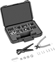
| 5/16" to 5/8" | 0.6" to 0.99" | 06, 08, 10, 12 | 5/16" | 0.024" | No | 122 | Cages with 5/16" band width for 5/16" hose ID (10 each) Clamps with 5/16" band width, .32" clamp ID (20 each) Cages with 5/16" band width for 13/32" hose ID (10 each) Clamps with 5/16" band width, .42" clamp ID (20 each) Cages with 5/16" band width for 1/2" hose ID (10 each) Clamps with 5/16" band width, .52" clamp ID (20 each) Cages with 5/16" band width for 5/8" hose ID (10 each) Clamps with 5/16" band width, .62" clamp ID (20 each) Pinch Clamp Pliers Hose Cutter | 0000000 | 0000000 |
Air Conditioning Hose


- Temperature Range: -20° to 180° F
- Material: Kevlar with Buna-N Rubber Cover
- Color: Black, Blue, Red, or Yellow
Use hose to charge and test your air conditioning units.
| Thread Size | ID | OD | Max. Pressure | Choose a Color | Each | |
3-ft. Lengths | ||||||
|---|---|---|---|---|---|---|
Brass Threaded UNF Female × Brass Threaded UNF Female | ||||||
| 5/8"-18 × 5/8"-18 | 5/16" | 5/8" | 600 psi @ 72° F | Black | 0000000 | 000000 |
Brass Threaded UNF Female × Brass 45° Flared UNF Female | ||||||
| 7/16"-20 × 7/16"-20 | 3/16" | 1/2" | 800 psi @ 72° F | 000000 | 00000 | |
5-ft. Lengths | ||||||
Brass Threaded UNF Female × Brass 45° Flared UNF Female | ||||||
| 7/16"-20 × 7/16"-20 | 3/16" | 1/2" | 800 psi @ 72° F | 000000 | 00000 | |
6-ft. Lengths | ||||||
Brass Threaded UNF Female × Brass Threaded UNF Female | ||||||
| 5/8"-18 × 5/8"-18 | 5/16" | 5/8" | 600 psi @ 72° F | Black | 0000000 | 00000 |
Brass Threaded UNF Female × Brass 45° Flared UNF Female | ||||||
| 7/16"-20 × 7/16"-20 | 3/16" | 1/2" | 800 psi @ 72° F | 000000 | 00000 | |
Brass Threaded UNF Female × Brass 45° Flared Ball Valve UNF Female | ||||||
| 7/16"-20 × 7/16"-20 | 3/16" | 1/2" | 800 psi @ 72° F | 0000000 | 00000 | |
Air Conditioning Hose Sets

- Temperature Range: -20° to 180° F
- Material: Kevlar with Buna-N Rubber Cover
- Color: Blue, Red, and Yellow
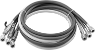
Each hose is a different color so you can differentiate your lines.
3-ft. Lengths | 5-ft. Lengths | 6-ft. Lengths | |||||||
|---|---|---|---|---|---|---|---|---|---|
| Thread Size | ID | OD | Max. Pressure | Each | Each | Each | |||
Brass Threaded UNF Female × Brass 45° Flared UNF Female | |||||||||
| 7/16"-20 × 7/16"-20 | 3/16" | 1/2" | 800 psi @ 72° F | 0000000 | 000000 | 0000000 | 000000 | 0000000 | 000000 |
Brass Threaded UNF Female × Brass 45° Flared Ball Valve UNF Female | |||||||||
| 7/16"-20 × 7/16"-20 | 3/16" | 1/2" | 800 psi @ 72° F | 000000 | 00 | 000000 | 00 | 0000000 | 000000 |
Threaded On/Off Valves for Refrigerant

- Valve Type: Ball
- For Use With: Refrigerant
- Seal Material: PTFE Plastic
- Specifications Met: NACE (National Association of Corrosion Engineers) MR0103, NACE (National Association of Corrosion Engineers) MR0175
Often used in HVAC or refrigeration systems, these valves are designed to control the flow of ammonia, nitrogen, and other harsh chemicals. To prevent accidental spills, a spring on the handle will automatically close the valve if you lose your grip. It’s also known as a deadman’s handle. The ball has a vent to relieve gas buildup when the valve is closed. Made from 316 stainless steel, these valves have excellent corrosion resistance.
Flow coefficient (Cv) is the amount of water (in gallons per minute) at 60° F that will flow through a fully open valve with a difference of 1 psi between the inlet and the outlet.
| Pipe Size | Flow Coefficient (Cv) | Max. Pressure | Temperature Range, °F | Vacuum Rating, in. of Hg | End-to-End Lg. | For Refrigerant Number | Features | Each | |
316 Stainless Steel Body | |||||||||
|---|---|---|---|---|---|---|---|---|---|
NPT Female × NPT Female | |||||||||
| 1/4 | 8.4 | 2,000 psi @ 100° F | -20° to 500° | 29 | 2 1/16" | R-134A, R-717, R-728, R-744 | Vented Ball | 0000000 | 0000000 |
| 3/8 | 7.2 | 2,000 psi @ 100° F | -20° to 500° | 29 | 2 1/16" | R-134A, R-717, R-728, R-744 | Vented Ball | 0000000 | 000000 |
| 1/2 | 15 | 2,000 psi @ 100° F | -20° to 500° | 29 | 2 1/4" | R-134A, R-717, R-728, R-744 | Vented Ball | 0000000 | 000000 |
| 3/4 | 30 | 2,000 psi @ 100° F | -20° to 500° | 29 | 3" | R-134A, R-717, R-728, R-744 | Vented Ball | 0000000 | 000000 |
| 1 | 43 | 2,000 psi @ 100° F | -20° to 500° | 29 | 3 3/8" | R-134A, R-717, R-728, R-744 | Vented Ball | 0000000 | 000000 |
On/Off Valves with Solder-Connect Fittings for Refrigerant
- Valve Type: Ball
- For Use With: Refrigerant
- Seal Material: PTFE Plastic
- Specifications Met: UL Listed, C-UL Listed, CE Marked
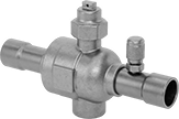
Install these valves in HVAC and refrigeration systems to control CO₂. They are operated with a wrench to give you the leverage needed to manage the flow of highly pressurized gases common in refrigeration systems. Because they require a wrench, these valves can’t be opened accidentally when bumped or snagged. Solder them to metal tubing for a permanent, leak-tight connection. To monitor pressure or fluid flow, attach a gauge to the port. The port can also be used to drain and divert liquid. These valves are full port, so they do not restrict flow.
Flow coefficient (Cv) is the amount of water (in gallons per minute) at 60° F that will flow through a fully open valve with a difference of 1 psi between the inlet and the outlet.
Gauge Ports | ||||||||||||||
|---|---|---|---|---|---|---|---|---|---|---|---|---|---|---|
| For Copper Tube Size | For Tube OD | No. of | Thread Size | Gender | Thread Type | Flow Coefficient (Cv) | Max. Pressure | Temperature Range, °F | End-to-End Lg. | Drive Style | Drive Size | For Refrigerant No. | Each | |
Wrench-Operated Brass Body | ||||||||||||||
Solder Connect × Solder Connect | ||||||||||||||
| 1/8 | 1/4" | 1 | 7/16"-20 | Male | UNF | 1 | 2,030 psi @ 300° F | -40° to 300° | 5" | External Hex | 13/16" | R-744 | 0000000 | 0000000 |
| 1/4 | 3/8" | 1 | 7/16"-20 | Male | UNF | 4.3 | 2,030 psi @ 300° F | -40° to 300° | 5 1/4" | External Hex | 13/16" | R-744 | 0000000 | 000000 |
| 3/8 | 1/2" | 1 | 7/16"-20 | Male | UNF | 6.2 | 2,030 psi @ 300° F | -40° to 300° | 5 1/2" | External Hex | 13/16" | R-744 | 0000000 | 000000 |
| 1/2 | 5/8" | 1 | 7/16"-20 | Male | UNF | 12.1 | 2,030 psi @ 300° F | -40° to 300° | 5 7/8" | External Hex | 13/16" | R-744 | 0000000 | 000000 |
| 5/8 | 3/4" | 1 | 7/16"-20 | Male | UNF | 19 | 2,030 psi @ 300° F | -40° to 300° | 5 7/8" | External Hex | 15/16" | R-744 | 0000000 | 000000 |
| 3/4 | 7/8" | 1 | 7/16"-20 | Male | UNF | 27.5 | 2,030 psi @ 300° F | -40° to 300° | 7 5/16" | External Hex | 15/16" | R-744 | 0000000 | 000000 |
| 1 | 1 1/8" | 1 | 7/16"-20 | Male | UNF | 48 | 2,030 psi @ 300° F | -40° to 300° | 7 5/16" | External Hex | 1 1/8" | R-744 | 0000000 | 000000 |
| 1 1/4 | 1 3/8" | 1 | 7/16"-20 | Male | UNF | 77 | 2,030 psi @ 300° F | -40° to 300° | 8 1/8" | External Hex | 1 1/8" | R-744 | 0000000 | 000000 |
| 1 1/2 | 1 5/8" | 1 | 7/16"-20 | Male | UNF | 96 | 2,030 psi @ 300° F | -40° to 300° | 9 1/2" | External Hex | 1 1/8" | R-744 | 0000000 | 000000 |
| 2 | 2 1/8" | 1 | 7/16"-20 | Male | UNF | 198 | 2,030 psi @ 300° F | -40° to 300° | 10 7/8" | External Hex | 1 5/8" | R-744 | 0000000 | 000000 |
Hot and Cold Tubes for Supplied-Air Respirators for Plant Air Lines

Adjust the temperature of the air flowing into your respirator. These tubes rapidly spin the air from your supply line to separate it into hot and cold streams. Turn a knob to control how much air from each stream flows into your respirator.
| OD | Lg. | Air Temp. Increase, °F | Air Temp. Reduction, °F | Material | Belt Material | Connection Type | Quick-Disconnect Shape | Coupling Size | Includes | Features | Each | |
For Cooling | ||||||||||||
|---|---|---|---|---|---|---|---|---|---|---|---|---|
| 1" | 8 1/4" | __ | 0° to 30° | Aluminum | Nylon Fabric | Quick Disconnect | Industrial | 1/4 | __ | Temperature Control Valve | 0000000 | 0000000 |
For Heating/Cooling | ||||||||||||
| 1" | 9" | 0° to 25° | 0° to 30° | Aluminum | Polypropylene Fabric | Quick Disconnect | Industrial | 1/4 | Cable Tie, Heat Shield | Temperature Control Valve | 00000000 | 000000 |


