


Select a cylinder, prolong its life by reducing wear, and trigger automated processes with sensors.
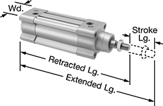
Clean Room Round Body Air Cylinders
Minimize the release of particles that can damage electronics or contaminate batches as you push and pull light loads. These air cylinders are designed with seals and caps that prevent particles from escaping. A rod seal wipes grease particles off the rod as it moves back and forth. The seal is polyurethane, which is slippery, so it wears more slowly than standard seals, releasing fewer particles. These cylinders also have tightly crimped end caps to stop air from leaking.
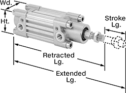
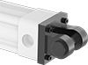
With no tie rods on the outside, these round-body cylinders fit in tight spaces. They have an ISO industry-standard footprint that fits common mounting patterns for easy interchangeability. As universal-mount cylinders, they have mounting threads on both ends, giving you more mounting options than nose-mount cylinders. You can also pivot mount them with the through-hole on the back. They’re double acting, meaning they push and pull loads with equal force.
The piston is magnetic, so you can use these cylinders with sensors (sold separately) to activate relays and controllers. When the piston moves past a sensor, the sensor activates. You can use multiple sensors—one for each action you want to trigger.
![]() For technical drawings and 3-D models, click on a part number.
For technical drawings and 3-D models, click on a part number.
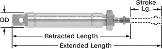
Lg., mm | Air Inlet | ||||||||||||
|---|---|---|---|---|---|---|---|---|---|---|---|---|---|
| Stroke | Retracted | Extended | Force @ 100 psi, lbs. | Environmental Rating | Air Cushion Type | Body Material | Rod Thread Size | Pipe Size | Thread Type | Gender | Specifications Met | Each | |
20mm Bore Size (21mm OD) | |||||||||||||
| 125 | 257 | 382 | 48 | Fed. Std. Class 1,000, ISO Class 6 | Self Adjusting | Aluminum | M8 × 1.25 mm | 1/8 | BSPP | Female | ISO 6432 | 0000000 | 000000 |
25mm Bore Size (27mm OD) | |||||||||||||
| 125 | 266.5 | 391.5 | 76 | Fed. Std. Class 1,000, ISO Class 6 | Self Adjusting | Aluminum | M10 × 1.25 mm | 1/8 | BSPP | Female | ISO 6432 | 0000000 | 000000 |
32mm Bore Size (42mm OD) | |||||||||||||
| 125 | 276.5 | 401.5 | 124 | Fed. Std. Class 1,000, ISO Class 6 | Self Adjusting | Aluminum | M10 × 1.25 mm | 1/8 | BSPP | Female | __ | 0000000 | 000000 |
40mm Bore Size (50mm OD) | |||||||||||||
| 125 | 302.6 | 427.6 | 194 | Fed. Std. Class 1,000, ISO Class 6 | Self Adjusting | Aluminum | M12 × 1.25 mm | 1/4 | BSPP | Female | __ | 0000000 | 000000 |
Instead of attaching your round body air cylinder directly to equipment, add a mount to best suit your application.
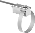
Foot brackets prevent cylinders from moving back and forth.
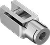
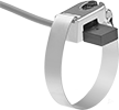
Pivot brackets for universal-mount air cylinders allow the rear portion of cylinders to pivot back and forth.
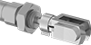
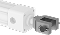
Rod clevises thread to cylinder shafts to allow swiveling.
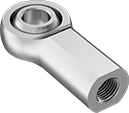
Rod ends are internally threaded. They have an eyelet and ball that swivel to support angular misalignment and allow for pivoting.
Rod end nuts are internally threaded. They have an eyelet to make pivoting and hinge movements.
Stainless steel mounts are more corrosion resistant than steel and aluminum for use in wet or damp environments.
| Shank Thread Size | ID, mm | Max. Ball Swivel | O'all Wd., mm | O'all Thick., mm | Shank Center Lg., mm | Shank Thread Lg., mm | Static Radial Load Cap., lbs. | Material | Shank Thread Direction | Each | |
| M8 × 1.25 mm | 8 | 18° | 22 | 12 | 36 | 17 | 7,450 | Zinc-Plated Chrome-Moly Steel | Right Hand | 00000000 | 000000 |
| M10 × 1.25 mm | 10 | 17° | 27 | 14 | 43 | 21 | 11,250 | Zinc-Plated Chrome-Moly Steel | Right Hand | 00000000 | 00000 |
| M12 × 1.25 mm | 12 | 17° | 30 | 16 | 50 | 24 | 10,000 | Zinc-Plated Chrome-Moly Steel | Right Hand | 00000000 | 00000 |
| Shank Thread Size | ID, mm | Jaw Opening Wd., mm | O'all Wd., mm | Shank Center Lg., mm | Shank Thread Lg., mm | Jaw Center Lg., mm | Tensile Strength, psi | Material | Includes | Shank Thread Direction | Specifications Met | Each | |
| M12 × 1.25 mm | 12 | 12 | 24 | 48 | 24 | 24 | 60,000 | Zinc-Plated Carbon Steel | Snap-On Spring Clevis Pin | Right Hand | DIN 71752 | 0000000 | 000000 |

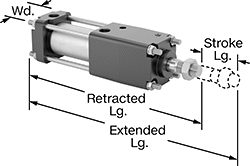
Enclosed-Body ISO Air Cylinders
An extruded-aluminum body means these cylinders have no open spaces for debris to collect. They have an ISO industry-standard footprint to match common mounting patterns for easy interchangeability. These cylinders are double-acting, so they exert force in both directions. To minimize wear and reduce noise, they cushion the impact of the piston with air. Adjust the amount of cushion with a screw at each port. All have a magnetic piston so, you can use them with sensors (sold separately) to activate relays and controllers. You can use multiple sensors—attach one for each action you want to trigger.
![]() For technical drawings and 3-D models, click on a part number.
For technical drawings and 3-D models, click on a part number.
Lg., mm | Air Inlet | ||||||||
|---|---|---|---|---|---|---|---|---|---|
| Stroke | Retracted | Extended | Force @ 100 psi, lbs. | Body Material | Pipe Size | Thread Type | Gender | Each | |
32 mm Bore Size (46.5 mm Wd.) | |||||||||
| 125 | 271 | 396 | 125 | Aluminum | 1/8 | BSPP | Female | 000000000 | 0000000 |
40 mm Bore Size (53 mm Wd.) | |||||||||
| 125 | 288 | 413 | 195 | Aluminum | 1/4 | BSPP | Female | 000000000 | 000000 |
63 mm Bore Size (75 mm Wd.) | |||||||||
| 125 | 319 | 444 | 483 | Aluminum | 3/8 | BSPP | Female | 000000000 | 000000 |
Connect these mounts to an air cylinder to create linear, pivot, or arc movements. These mounts are compatible with ISO tie rod air cylinders.
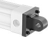
Front or rear flanges are for straightforward, back-and-forth movements, such as opening a sliding door. These flanges mount to either end of your cylinder.
Pivot brackets and clevis brackets work together to allow the rear portion of cylinders to pivot back and forth. Use either with a rod clevis to create arcing movements, such as opening a swinging door. Rod clevises allow the front portion of cylinders to pivot.
Stainless steel mounts are more corrosion resistant than steel and aluminum for use in wet or damp environments.
Connect these mounts to an air cylinder to create linear, pivot, or arc movements. These mounts are compatible with ISO tie rod air cylinders.
Front or rear flanges are for straightforward, back-and-forth movements, such as opening a sliding door. These flanges mount to either end of your cylinder.
Pivot brackets and clevis brackets work together to allow the rear portion of cylinders to pivot back and forth. Use either with a rod clevis to create arcing movements, such as opening a swinging door. Rod clevises allow the front portion of cylinders to pivot.
Stainless steel mounts are more corrosion resistant than steel and aluminum for use in wet or damp environments.
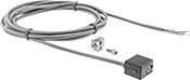
| For Bore Size | AC Voltage | DC Voltage | Electrical Connection | Temperature Range, °F | Each | |
Reed Switch | ||||||
|---|---|---|---|---|---|---|
| 32mm, 40mm, 63mm | 12V AC- 240V AC | 12V DC- 60V DC | Wire Leads | -4° to 176° | 00000000 | 0000000 |
Enclosed-Body Load Responsive Cushion Air Cylinders
Ensure the correct cushioning, even with changing loads. These cylinders have self-adjusting cushions that automatically compensate for changes in load and speed. They have an extruded-aluminum body so there's no open spaces for debris to collect. All have a magnetic piston so you can use them with sensors (sold separately) to activate relays and controllers.
![]() For technical drawings and 3-D models, click on a part number.
For technical drawings and 3-D models, click on a part number.
Lg., mm | Air Inlet | |||||||||
|---|---|---|---|---|---|---|---|---|---|---|
| Stroke | Retracted | Extended | Force @ 100 psi, lbs. | Body Material | Pipe Size | Thread Type | Gender | Specifications Met | Each | |
32 mm Bore Size (45 mm Wd.) | ||||||||||
| 125 | 270.1 | 395.1 | 114 | Aluminum | 1/8 | BSPP | Female | ISO 15552, ISO 6431 | 00000000 | 0000000 |
40 mm Bore Size (54 mm Wd.) | ||||||||||
| 125 | 286.9 | 411.9 | 178 | Aluminum | 1/4 | BSPP | Female | ISO 15552, ISO 6431 | 00000000 | 000000 |
63 mm Bore Size (75 mm Wd.) | ||||||||||
| 125 | 318.1 | 443.1 | 441 | Aluminum | 3/8 | BSPP | Female | ISO 15552, ISO 6431 | 00000000 | 000000 |

Mounting Holes | |||||||||||||
|---|---|---|---|---|---|---|---|---|---|---|---|---|---|
| For Bore Size, mm | Pin Hole Dia., mm | Wd., mm | Ht., mm | Dp., mm | Base Plate Thick., mm | No. of | Dia., mm | Ctr.-to-Ctr., mm | Mounting Hardware Included | Material | Includes | Each | |
| 32 | 10 | 45 | 45 | 37 | 5.5 | 4 | 6.6 | 32.5 | Yes | Aluminum | Four Bolts | 00000000 | 000000 |
| 40 | 12 | 54 | 54 | 42 | 5.5 | 4 | 6.6 | 38 | Yes | Aluminum | Four Bolts | 00000000 | 00000 |
| 63 | 16 | 75 | 75 | 55 | 6.5 | 4 | 9 | 56.5 | Yes | Aluminum | Four Bolts | 00000000 | 000000 |

Pin | Mounting Holes | |||||||||||||||
|---|---|---|---|---|---|---|---|---|---|---|---|---|---|---|---|---|
| For Bore Size, mm | Dia., mm | Lg., mm | Material | Wd., mm | Ht., mm | Dp., mm | Jaw Opening Wd., mm | Base Plate Thick., mm | No. of | Dia., mm | Ctr.-to-Ctr., mm | Mounting Hardware Included | Material | Includes | Each | |
| 32 | 10 | 41 | Steel | 45 | 45 | 32 | 14 | 5.5 | 4 | 6.6 | 32.5 | Yes | Aluminum | Four Bolts, Retaining Clip | 00000000 | 000000 |
| 40 | 12 | 48 | Steel | 54 | 54 | 37 | 16 | 5.5 | 4 | 6.6 | 38 | Yes | Aluminum | Four Bolts, Retaining Clip | 00000000 | 00000 |
| 63 | 16 | 60 | Steel | 75 | 75 | 48 | 21 | 6.5 | 4 | 9 | 56.5 | Yes | Aluminum | Four Bolts, Retaining Clip | 00000000 | 00000 |
Pin | Shank | Thread | ||||||||||||||||
|---|---|---|---|---|---|---|---|---|---|---|---|---|---|---|---|---|---|---|
| For Bore Size, mm | Dia., mm | Lg., mm | Material | Lg., mm | Ht., mm | Jaw Opening Wd., mm | Center Lg., mm | Gender | Size | Pitch, mm | Lg., mm | No. of Mounting Holes | Mounting Hardware Included | Material | Includes | Specifications Met | Each | |
| 32 | 10 | 26 | Steel | 52 | 20 | 10 | 40 | Female | M10 | 1.25 | 20 | 4 | Yes | Galvanized Steel | Nut | DIN 71752, ISO 8140 | 00000000 | 000000 |
| 40 | 12 | 31 | Steel | 62 | 24 | 12 | 48 | Female | M12 | 1.25 | 24 | 4 | Yes | Galvanized Steel | Nut | DIN 71752, ISO 8140 | 00000000 | 00000 |
| 63 | 16 | 39 | Steel | 83 | 32 | 16 | 64 | Female | M16 | 1.5 | 32 | 4 | Yes | Galvanized Steel | Nut | DIN 71752, ISO 8140 | 00000000 | 00000 |
Locking Tie Rod Air Cylinders
Halt actuation at a moment’s notice—these air cylinders have an end lock that acts as an emergency stop. If there's a sudden loss of air pressure, the end lock engages to safely hold the load. You can also set them to stop anywhere along the stroke length as a simpler alternative to electric actuators. Rods along the barrel secure the end caps and shield the barrel from impact. These air cylinders are double acting, meaning they extend and retract with nearly equal force. All have adjustable air cushions that absorb piston impact to minimize wear and noise.
The magnetic piston inside these cylinders can activate relays and controllers when used with a sensor (sold separately). When the piston moves past the sensor, the sensor activates. You can use multiple sensors—attach one for each action to trigger.
![]() For technical drawings and 3-D models, click on a part number.
For technical drawings and 3-D models, click on a part number.
Lg. | Air Inlet | ||||||||
|---|---|---|---|---|---|---|---|---|---|
| Stroke, mm | Retracted, mm | Extended, mm | Force @ 100 psi, lbs. | Body Material | Pipe Size | Thread Type | Gender | Each | |
40 mm Bore Size (60 mm Wd.) | |||||||||
| 125 | 340 | 465 | 176 | Aluminum | 1/4 | NPT | Female | 0000000 | 0000000 |
50 mm Bore Size (70 mm Wd.) | |||||||||
| 125 | 362 | 487 | 314 | Aluminum | 3/8 | NPT | Female | 0000000 | 000000 |
63 mm Bore Size (86 mm Wd.) | |||||||||
| 125 | 379 | 504 | 490 | Aluminum | 3/8 | NPT | Female | 0000000 | 000000 |
80 mm Bore Size (102 mm Wd.) | |||||||||
| 125 | 431 | 556 | 830 | Aluminum | 1/2 | NPT | Female | 0000000 | 000000 |

Inside Mounting Holes | Outside Mounting Holes | ||||||||||||||
|---|---|---|---|---|---|---|---|---|---|---|---|---|---|---|---|
| For Bore Size, mm | Wd., mm | Ht., mm | Thick., mm | No. of | Dia., mm | Ctr.-to-Ctr., mm | Mounting Hardware Included | No. of | Dia., mm | Ctr.-to-Ctr., mm | Mounting Hardware Included | Material | Includes | Each | |
| 40 | 100 | 71 | 12 | 4 | 10 | 44 | Yes | 4 | 9 | 80 | No | Aluminum | Four Mounting Nuts | 00000000 | 000000 |
| 50 | 110 | 81 | 12 | 4 | 10 | 52 | Yes | 4 | 9 | 90 | No | Aluminum | Four Mounting Nuts | 00000000 | 00000 |
| 63 | 130 | 101 | 15 | 4 | 12 | 64 | Yes | 4 | 11 | 108 | No | Aluminum | Four Mounting Nuts | 00000000 | 00000 |
| 80 | 160 | 119 | 18 | 4 | 14 | 78 | Yes | 4 | 13 | 130 | No | Aluminum | Four Mounting Nuts | 00000000 | 00000 |

Mounting Hole | ||||||||||||
|---|---|---|---|---|---|---|---|---|---|---|---|---|
| For Bore Size, mm | For Pin Dia., mm | Wd., mm | Ht., mm | Dp., mm | Base Plate Thick., mm | Dia., mm | Ctr.-to-Ctr., mm | Mounting Fasteners Included | Material | Includes | Each | |
| 40 | 10 | 60 | 60 | 40 | 14 | 10 | 44 | No | Aluminum | Four Mounting Nuts | 00000000 | 000000 |
| 50 | 12 | 70 | 70 | 47 | 16 | 10 | 52 | No | Aluminum | Four Mounting Nuts | 00000000 | 00000 |
| 63 | 16 | 85 | 85 | 56 | 17 | 12 | 64 | No | Aluminum | Four Mounting Nuts | 00000000 | 00000 |
| 80 | 20 | 102 | 102 | 68 | 20 | 14 | 78 | No | Aluminum | Four Mounting Nuts | 00000000 | 00000 |

Mounting Hole | |||||||||||
|---|---|---|---|---|---|---|---|---|---|---|---|
| For Bore Size, mm | Wd., mm | Ht., mm | Dp., mm | Base Plate Thick., mm | Dia., mm | Ctr.-to-Ctr., mm | Mounting Fasteners Included | Material | Includes | Each | |
| 40 | 60 | 60 | 40 | 14 | 9 | 44 | No | Aluminum | Clevis Pin, Two Cotter Pins | 00000000 | 000000 |
| 50 | 70 | 70 | 47 | 16 | 9 | 52 | No | Aluminum | Clevis Pin, Two Cotter Pins | 00000000 | 00000 |
| 63 | 86 | 86 | 56 | 17 | 10 | 64 | No | Aluminum | Clevis Pin, Two Cotter Pins | 00000000 | 00000 |
| 80 | 102 | 102 | 68 | 20 | 13 | 78 | No | Aluminum | Clevis Pin, Two Cotter Pins | 00000000 | 00000 |
| For Bore Size | AC Voltage | DC Voltage | Each | |
| 1 1/4", 1 3/4", 2", 2 1/2", 3", 3 1/2", 4 1/2", 32mm, 40mm, 50mm, 63mm, 80mm | 5V AC- 240V AC | 5V DC- 240V DC | 00000000 | 000000 |