


Filter by
Height
Material
Alignment Lock Type
DFARS Specialty Metals
Export Control Classification Number (ECCN)
Release Type

Alignment Locks
Top Alignment Locks
 |  |
Top locks install where the two halves of your mold meet, often called the parting line. Top locks require separately machined pockets on each half of your mold for installation. Because you’re machining both sides separately, you’ll need to take extra care to make sure the two pockets are aligned.
Overall | Male | Female | Mounting | ||||||||||
|---|---|---|---|---|---|---|---|---|---|---|---|---|---|
Wd. | Wd. Tolerance | Ht. | Dp. | Ht. | Material | Ht. | Material | No. of Holes | For Fastener Thread Size | Fasteners Included | Each | ||
| 1 1/4" | -0.0004" to 0" | 1 1/8" | 3/4" | 1/2" | Black-Oxide Steel | 5/8" | Titanium Nitride (TiN)-Coated Steel | 4 | 8-32 | No | 7237N55 | 0000000 | |
| 2" | -0.0004" to 0" | 1 1/2" | 1 1/8" | 5/8" | Black-Oxide Steel | 7/8" | Titanium Nitride (TiN)-Coated Steel | 4 | 1/4"-20 | No | 7237N56 | 000000 | |
| 3" | -0.0004" to 0" | 2 1/8" | 1 3/4" | 7/8" | Black-Oxide Steel | 1 1/4" | Titanium Nitride (TiN)-Coated Steel | 4 | 5/16"-18 | No | 7237N57 | 000000 | |
Side Alignment Locks
 |  |
Overall | Male | Female | Mounting | |||||||||||
|---|---|---|---|---|---|---|---|---|---|---|---|---|---|---|
Wd. | Wd. Tolerance | Ht. | Ht. Tolerance | Dp. | Ht. | Material | Ht. | Material | No. of Holes | For Fastener Thread Size | Fasteners Included | Each | ||
| 1" | -0.0004" to 0" | 2" | -0.005" to 0" | 3/8" | 7/8" | Black-Oxide Steel | 1 1/8" | Titanium Nitride (TiN)-Coated Steel | 4 | 10-32 | No | 7237N58 | 0000000 | |
| 1 1/4" | -0.0004" to 0" | 2" | -0.005" to 0" | 1/2" | 7/8" | Black-Oxide Steel | 1 1/8" | Titanium Nitride (TiN)-Coated Steel | 4 | 8-32 | No | 7237N59 | 000000 | |
| 1 1/2" | -0.0004" to 0" | 1 3/4" | -0.005" to 0" | 1/2" | 7/8" | Black-Oxide Steel | 7/8" | Titanium Nitride (TiN)-Coated Steel | 4 | 8-32 | No | 7237N61 | 000000 | |
| 2" | -0.0004" to 0" | 2 1/4" | -0.005" to 0" | 1/2" | 7/8" | Black-Oxide Steel | 1 3/8" | Titanium Nitride (TiN)-Coated Steel | 4 | 10-32 | No | 7237N62 | 000000 | |
| 3" | -0.0004" to 0" | 2 3/4" | -0.005" to 0" | 3/4" | 7/8" | Black-Oxide Steel | 1 7/8" | Titanium Nitride (TiN)-Coated Steel | 4 | 1/4"-20 | No | 7237N63 | 000000 | |
| 4" | -0.0004" to 0" | 3 3/4" | -0.005" to 0" | 1" | 1 3/8" | Black-Oxide Steel | 2 3/8" | Titanium Nitride (TiN)-Coated Steel | 4 | 3/8"-16 | No | 7237N64 | 000000 | |
| 5" | -0.0004" to 0" | 4 1/4" | -0.005" to 0" | 1 1/4" | 1 3/8" | Black-Oxide Steel | 2 7/8" | Titanium Nitride (TiN)-Coated Steel | 4 | 1/2"-13 | No | 7237N65 | 000000 | |
| 6" | -0.0004" to 0" | 4 1/4" | -0.005" to 0" | 1 1/2" | 1 3/8" | Black-Oxide Steel | 2 7/8" | Titanium Nitride (TiN)-Coated Steel | 4 | 1/2"-13 | No | 7237N66 | 000000 | |
Tapered Round Alignment Locks
 |  |
Male | Female |
 |
Male |
 |
Female |
Tapered round locks prevent sliding in all directions unlike top and side locks, which only prevent sliding in one direction. Install them where the two halves of the mold meet, often called the parting line. You’ll need to machine pockets in each half of your mold separately, so you’ll need to take extra care to make sure the two pockets are aligned. For a complete pair, you’ll need a male and female lock with matching ODs. The height does not need to match.
Mounting | Male | Female | ||||||||||
|---|---|---|---|---|---|---|---|---|---|---|---|---|
OD | OD Tolerance | ID | Material | No. of Holes | For Fastener Thread Size | Fasteners Included | Choose a Height | Each | Each | |||
| 1/2" | -0.0005" to 0" | 5/16" | Steel | 1 | 10-24 | No | 11/16", 7/8", 1 3/16", 1 3/8" | 7237N73 | 000000 | 7237N67 | 000000 | |
| 3/4" | -0.0005" to 0" | 1/2" | Steel | 1 | 1/4"-20 | No | 11/16", 7/8", 1 3/16", 1 3/8" | 7237N74 | 00000 | 7237N68 | 00000 | |
| 1" | -0.0005" to 0" | 5/8" | Steel | 1 | 1/4"-20 | No | 11/16", 7/8", 1 3/16", 1 3/8" | 7237N75 | 00000 | 7237N69 | 00000 | |
| 1 1/2" | -0.0005" to 0" | 1" | Steel | 1 | 5/16"-18 | No | 1 1/8", 1 3/8", 1 5/8" | 7237N76 | 00000 | 7237N71 | 00000 | |
| 2" | -0.0005" to 0" | 1 1/2" | Steel | 1 | 5/16"-18 | No | 1 1/8", 1 3/8", 1 5/8" | 7237N77 | 00000 | 7237N72 | 00000 | |
Guide Alignment Locks
 |  |
Overall | Male | Female | Mounting | |||||||||||
|---|---|---|---|---|---|---|---|---|---|---|---|---|---|---|
Wd. | Ht. | Ht. Tolerance | Dp. | Dp. Tolerance | Ht. | Material | Ht. | Material | No. of Holes | For Fastener Thread Size | Fasteners Included | Each | ||
| 1 1/2" | 0.85" | -0.01" to 0" | 1" | -0.01" to 0" | 0.85" | Black-Oxide Steel | 1/2" | Titanium Nitride (TiN)-Coated Steel | 6 | 10-32 | No | 7237N51 | 0000000 | |
| 2 1/2" | 1.35" | -0.01" to 0" | 1 1/2" | -0.01" to 0" | 1.35" | Black-Oxide Steel | 3/4" | Titanium Nitride (TiN)-Coated Steel | 6 | 1/4"-20 | No | 7237N52 | 000000 | |
| 3 1/2" | 1.73" | -0.01" to 0" | 2" | -0.01" to 0" | 1.73" | Black-Oxide Steel | 1" | Titanium Nitride (TiN)-Coated Steel | 6 | 3/8"-16 | No | 7237N53 | 000000 | |
| 4 1/2" | 2.1" | -0.01" to 0" | 2 1/2" | -0.01" to 0" | 2.1" | Black-Oxide Steel | 1 1/4" | Titanium Nitride (TiN)-Coated Steel | 6 | 1/2"-13 | No | 7237N54 | 000000 | |
Self-Aligning Remote-Release Rotary Latches with Safety Catch
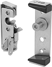 |  |
2 Latch Points | 1 Latch Point |
The slanted edges on these latches guide them into the strike bolt on your door, so the door will close even if it’s misaligned. They’re also known as dovetail latches and two-stage rotary latches. A safety catch stops your door from opening accidentally if it’s not pushed in all the way. You’ll know it’s not fully latched if the door rattles. Give the door an extra push to shut it completely. When closed, these latches grip the strike bolt on your door to hold it firmly shut. They require over 700 lbs. of pulling force to yank open, so they stay closed even in demanding applications. To open these latches remotely, you can connect them to a handle with a cable or rod (not included). This is especially useful when you want your latch hidden but your handle in an easy-to-reach spot.
2 Latch Points—Latches with two latch points let you open the latch using two handles.
FMVSS No. 206—FMVSS No. 206 rated latches have been designed and tested to meet rigorous Federal Motor Vehicle Safety Standard requirements.
Strike Plate | Strike Bolt | ||||||||||||||||||||||||||||||||||||||||||||||||||||||||||||||||||||||||||||||||||||||||||||||||||
|---|---|---|---|---|---|---|---|---|---|---|---|---|---|---|---|---|---|---|---|---|---|---|---|---|---|---|---|---|---|---|---|---|---|---|---|---|---|---|---|---|---|---|---|---|---|---|---|---|---|---|---|---|---|---|---|---|---|---|---|---|---|---|---|---|---|---|---|---|---|---|---|---|---|---|---|---|---|---|---|---|---|---|---|---|---|---|---|---|---|---|---|---|---|---|---|---|---|---|---|
Max. Pull Strength, lbf | No. of Latch Points | Lg. | Wd. | Dp. | Max. Latching Distance | Lg. | Wd. | Projection | Mounting Hole Dia. | Mounting Hole Ctr.-to-Ctr. | Dia. | Lg. | Projection | Thread Size | Latch Point Hole Dia. | Specs. Met | Each | ||||||||||||||||||||||||||||||||||||||||||||||||||||||||||||||||||||||||||||||||||
Zinc-Plated Steel (Dull) | |||||||||||||||||||||||||||||||||||||||||||||||||||||||||||||||||||||||||||||||||||||||||||||||||||
Left-Side Door Mount | |||||||||||||||||||||||||||||||||||||||||||||||||||||||||||||||||||||||||||||||||||||||||||||||||||
| 750 | 2 | 4 7/8" | 1 5/8" | 3/4" | 3/4" | 5 3/4" | 1 7/8" | 1 1/8" | 5/16" | 3 3/4" | 9/16" | 1 3/4" | 1" | 7/16"-14 | 1/4" | FMVSS No. 206 | 5226N14 | 000000 | |||||||||||||||||||||||||||||||||||||||||||||||||||||||||||||||||||||||||||||||||
| 1,500 | 1 | 4 7/8" | 1 5/8" | 3/4" | 3/4" | 5 3/4" | 1 7/8" | 1 1/8" | 5/16" | 3 3/4" | 9/16" | 1 3/4" | 1" | 7/16"-14 | 1/4" | — | 5226N12 | 00000 | |||||||||||||||||||||||||||||||||||||||||||||||||||||||||||||||||||||||||||||||||
Right-Side Door Mount | |||||||||||||||||||||||||||||||||||||||||||||||||||||||||||||||||||||||||||||||||||||||||||||||||||
| 750 | 2 | 4 7/8" | 1 5/8" | 3/4" | 3/4" | 5 3/4" | 1 7/8" | 1 1/8" | 5/16" | 3 3/4" | 9/16" | 1 3/4" | 1" | 7/16"-14 | 1/4" | FMVSS No. 206 | 5226N13 | 00000 | |||||||||||||||||||||||||||||||||||||||||||||||||||||||||||||||||||||||||||||||||
| 1,500 | 1 | 4 7/8" | 1 5/8" | 3/4" | 3/4" | 5 3/4" | 1 7/8" | 1 1/8" | 5/16" | 3 3/4" | 9/16" | 1 3/4" | 1" | 7/16"-14 | 1/4" | — | 5226N11 | 00000 | |||||||||||||||||||||||||||||||||||||||||||||||||||||||||||||||||||||||||||||||||
Remote-Release Rotary Latches with Cable and Handle
T-Handle Release
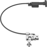 |
T-handle release latches open by pulling the handle.
300 Series Stainless Steel—300 series stainless steel latches won’t rust in damp or humid environments.
Maximum Cumulative Bend—Maximum cumulative bend is the combined total of individual bend angles the cable can withstand along its length.
Handle | Handle Plate | Strike Bolt | 3 ft. Long Cable | 5 ft. Long Cable | |||||||||||||||||||||||||||||||||||||||||||||||||||||||||||||||||||||||||||||||||||||||||||||||
|---|---|---|---|---|---|---|---|---|---|---|---|---|---|---|---|---|---|---|---|---|---|---|---|---|---|---|---|---|---|---|---|---|---|---|---|---|---|---|---|---|---|---|---|---|---|---|---|---|---|---|---|---|---|---|---|---|---|---|---|---|---|---|---|---|---|---|---|---|---|---|---|---|---|---|---|---|---|---|---|---|---|---|---|---|---|---|---|---|---|---|---|---|---|---|---|---|---|---|---|
Max. Pull Strength, lbf | Lg. | Wd. | Dp. | Cable Dia. | Max. Latching Distance | Lg. | Wd. | Lg. | Wd. | Mounting Hole Dia. | Mounting Hole Ctr.-to-Ctr. | Mounting Fasteners Included | Dia. | Lg. | Projection | Max. Cumulative Bend | Each | Each | |||||||||||||||||||||||||||||||||||||||||||||||||||||||||||||||||||||||||||||||||
300 Series Stainless Steel (Dull) | |||||||||||||||||||||||||||||||||||||||||||||||||||||||||||||||||||||||||||||||||||||||||||||||||||
Left-Side Door Mount | |||||||||||||||||||||||||||||||||||||||||||||||||||||||||||||||||||||||||||||||||||||||||||||||||||
| 900 | 2 11/16" | 1 7/8" | 3/4" | 1/4" | 5/8" | 2 3/8" | 7/8" | 2 3/16" | 1 3/4" | 3/16" | 1", 1 9/16" | No | 3/8" | 1 1/2" | 1" | 720° | 2069N13 | 000000 | 2069N14 | 0000000 | |||||||||||||||||||||||||||||||||||||||||||||||||||||||||||||||||||||||||||||||
Right-Side Door Mount | |||||||||||||||||||||||||||||||||||||||||||||||||||||||||||||||||||||||||||||||||||||||||||||||||||
| 900 | 2 11/16" | 1 7/8" | 3/4" | 1/4" | 5/8" | 2 3/8" | 7/8" | 2 3/16" | 1 3/4" | 3/16" | 1", 1 9/16" | No | 3/8" | 1 1/2" | 1" | 720° | 2069N11 | 00000 | 2069N12 | 000000 | |||||||||||||||||||||||||||||||||||||||||||||||||||||||||||||||||||||||||||||||
Push-Button Release
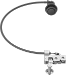 |
Push-button release latches open when you press the button.
300 Series Stainless Steel—300 series stainless steel latches won’t rust in damp or humid environments.
Maximum Cumulative Bend—Maximum cumulative bend is the combined total of individual bend angles the cable can withstand along its length.
Strike Bolt | 3 ft. Long Cable | 5 ft. Long Cable | |||||||||||||||||||||||||||||||||||||||||||||||||||||||||||||||||||||||||||||||||||||||||||||||||
|---|---|---|---|---|---|---|---|---|---|---|---|---|---|---|---|---|---|---|---|---|---|---|---|---|---|---|---|---|---|---|---|---|---|---|---|---|---|---|---|---|---|---|---|---|---|---|---|---|---|---|---|---|---|---|---|---|---|---|---|---|---|---|---|---|---|---|---|---|---|---|---|---|---|---|---|---|---|---|---|---|---|---|---|---|---|---|---|---|---|---|---|---|---|---|---|---|---|---|---|
Max. Pull Strength, lbf | Lg. | Wd. | Dp. | Cable Dia. | Max. Latching Distance | Button Dia. | Mounting Fasteners Included | Dia. | Lg. | Projection | Max. Cumulative Bend | Each | Each | ||||||||||||||||||||||||||||||||||||||||||||||||||||||||||||||||||||||||||||||||||||||
300 Series Stainless Steel (Dull) | |||||||||||||||||||||||||||||||||||||||||||||||||||||||||||||||||||||||||||||||||||||||||||||||||||
Left-Side Door Mount | |||||||||||||||||||||||||||||||||||||||||||||||||||||||||||||||||||||||||||||||||||||||||||||||||||
| 900 | 2 11/16" | 1 7/8" | 3/4" | 1/4" | 5/8" | 1 1/2" | No | 3/8" | 1 1/2" | 1" | 720° | 2069N17 | 000000 | 2069N18 | 0000000 | ||||||||||||||||||||||||||||||||||||||||||||||||||||||||||||||||||||||||||||||||||||
Right-Side Door Mount | |||||||||||||||||||||||||||||||||||||||||||||||||||||||||||||||||||||||||||||||||||||||||||||||||||
| 900 | 2 11/16" | 1 7/8" | 3/4" | 1/4" | 5/8" | 1 1/2" | No | 3/8" | 1 1/2" | 1" | 720° | 2069N15 | 00000 | 2069N16 | 000000 | ||||||||||||||||||||||||||||||||||||||||||||||||||||||||||||||||||||||||||||||||||||
