


Filter by
For Use With
Valve Function
Body Material
Seal Material


Inlet Connection
Outlet Gender
DFARS Specialty Metals
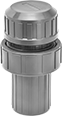
Plastic Panel-Mount Vacuum-Regulating Valves for Air and Inert Gas
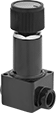 |
A lighter and more corrosion-resistant alternative to metal valves. All valves throttle a high vacuum source to maintain a lower vacuum level in your system. Adjust the outlet vacuum level within the range. Threads below the adjustment knob and an included panel-mount nut let you add these valves to your instrument panel. All are constant-bleed style, so they continually release small amounts of process gas to improve accuracy and repeatability.
Inlet | Outlet | |||||||||||||||
|---|---|---|---|---|---|---|---|---|---|---|---|---|---|---|---|---|
Pipe Size | Thread Size | Location | Pipe Size | Thread Size | Location | Vacuum Range, in. Hg | Vacuum Adjustment Method | End-to-End Lg. | Bleed Type | Panel Cutout Dia. | For Use With | Temp. Range, ° F | Each | |||
NPT Female | ||||||||||||||||
Polysulfone Body—Buna-N/EPDM Diaphragm and Polyurethane Rubber Seal | ||||||||||||||||
| 1/8 | — | Side | 1/8 | — | Side | 0 to 30 | Knob | 1 9/16" | Constant Bleed | 9/16" | Air, Inert Gas | 40 to 150 | 41585K43 | 000000 | ||
UNF Female | ||||||||||||||||
Polysulfone Body—Buna-N/EPDM Diaphragm and Polyurethane Rubber Seal | ||||||||||||||||
| — | 10-32 | Side | — | 10-32 | Side | 0 to 30 | Knob | 1 1/8" | Constant Bleed | 9/16" | Air, Inert Gas | 40 to 150 | 41585K41 | 00000 | ||
Extended-Life Vacuum-Regulating Valves for Air and Inert Gas
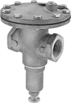 |
For a longer service life than brass vacuum-regulating valves, these are made of bronze for strength and durability. They throttle a high vacuum source to maintain a lower vacuum level in your system. Turning the adjustment screw will adjust the vacuum setting.
Inlet | Outlet | |||||||||||
|---|---|---|---|---|---|---|---|---|---|---|---|---|
Pipe Size | Location | Pipe Size | Location | Vacuum Range, in. Hg | Vacuum Adjustment Method | End-to-End Lg. | For Use With | Temp. Range, ° F | Each | |||
NPT Female | ||||||||||||
Bronze Body—Neoprene Diaphragm and Chrome-Plated Bronze Seal | ||||||||||||
| 1/2 | Side | 1/2 | Side | 2 to 30 | Screw | 2 7/8" | Air, Inert Gas | -20 to 180 | 4710K11 | 0000000 | ||
| 3/4 | Side | 3/4 | Side | 2 to 30 | Screw | 2 7/8" | Air, Inert Gas | -20 to 180 | 4710K13 | 000000 | ||
| 1 | Side | 1 | Side | 2 to 30 | Screw | 4 1/2" | Air, Inert Gas | -20 to 180 | 4710K15 | 00000000 | ||
| 1 1/4 | Side | 1 1/4 | Side | 2 to 30 | Screw | 4 1/2" | Air, Inert Gas | -20 to 180 | 4710K17 | 00000000 | ||
| 1 1/2 | Side | 1 1/2 | Side | 8 to 30 | Screw | 5 3/4" | Air, Inert Gas | -20 to 180 | 4710K18 | 00000000 | ||
| 2 | Side | 2 | Side | 8 to 30 | Screw | 5 3/4" | Air, Inert Gas | -20 to 180 | 4710K19 | 00000000 | ||
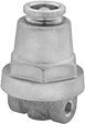
Adjustable Vacuum-Relief Valves for Air and Inert Gas
These valves begin opening at the set vacuum level and fully open at about 10% over the set point. They begin closing as the vacuum level drops and fully close when the system is restored below the set point. Adjust the set vacuum level within the range. Valves have a vented relief port to exhaust discharge directly.
Inlet | Vacuum Set Point | ||||||||||
|---|---|---|---|---|---|---|---|---|---|---|---|
Pipe Size | Location | Relief Port Location | Range, in. Hg | Adjustment Method | Overall Ht. | For Use With | Temp. Range, ° F | Each | |||
NPT Male Inlet and Vacuum Relief Vent | |||||||||||
Brass Body—440C Stainless Steel Seal | |||||||||||
| 1/4 | Bottom | Top | 0 to 27 | External Adjustment Screw | 1 3/4" | Air, Inert Gas | -15 to 250 | 48935K25 | 00000 | ||
Brass Body—Buna-N Seal | |||||||||||
| 3/8 | Bottom | Top | 0 to 27 | External Adjustment Screw | 2 1/16" | Air, Inert Gas | -15 to 250 | 48935K35 | 00000 | ||
| 3/4 | Bottom | Top | 0 to 27 | External Adjustment Screw | 2 5/8" | Air, Inert Gas | -15 to 250 | 48935K45 | 00000 | ||
Vacuum-Regulating Valves for Air and Inert Gas
 |
Throttle a high vacuum source to maintain a lower vacuum level in your system. Adjust the outlet vacuum level within the range. All valves have a gauge port.
Inlet | Outlet | ||||||||||||
|---|---|---|---|---|---|---|---|---|---|---|---|---|---|
Pipe Size | Location | Pipe Size | Location | Vacuum Range, in. Hg | Vacuum Adjustment Method | Vacuum Gauge Included | End-to-End Lg. | For Use With | Temp. Range, ° F | Each | |||
NPT Female | |||||||||||||
Brass Body—EPM Rubber Diaphragm and Buna-N Seal | |||||||||||||
| 1/4 | Bottom | 1/4 | Side | 0 to 15 | Screw | No | 1 3/4" | Air, Carbon Dioxide, Inert Gas, Nitrogen | -20 to 180 | 5021K14 | 0000000 | ||
| 1/4 | Bottom | 1/4 | Side | 10 to 30 | Screw | No | 1 3/4" | Air, Carbon Dioxide, Inert Gas, Nitrogen | -20 to 180 | 5021K24 | 000000 | ||
High-Accuracy Panel-Mount Vacuum-Regulating Valves for Air and Inert Gas
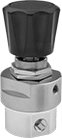 |
For precise control over your vacuum level, these valves have ±0.1% accuracy. They throttle a high vacuum source to maintain a lower vacuum level in your system. Adjust the outlet vacuum level within the range. Valves have threads below the adjustment knob and come with a panel-mount nut. All have a gauge port. They are constant-bleed style, so they continually release small amounts of process gas to improve accuracy and repeatability.
Inlet | Outlet | ||||||||||||||
|---|---|---|---|---|---|---|---|---|---|---|---|---|---|---|---|
Pipe Size | Location | Pipe Size | Location | Vacuum Range, in. Hg | Vacuum Adjustment Method | Vacuum Gauge Included | End-to-End Lg. | Bleed Type | Panel Cutout Dia. | For Use With | Temp. Range, ° F | Each | |||
NPT Female | |||||||||||||||
Brass Body—Buna-N Diaphragm and Buna-N Seal | |||||||||||||||
| 1/8 | Side | 1/8 | Side | 0 to 25 | Knob | No | 2 1/8" | Constant Bleed | 1 3/8" | Air, Argon, Nitrogen | -40 to 165 | 4640T71 | 0000000 | ||
| 1/4 | Side | 1/4 | Side | 0 to 25 | Knob | No | 2 1/8" | Constant Bleed | 1 3/8" | Air, Argon, Nitrogen | -40 to 165 | 4640T72 | 000000 | ||
Vacuum Breakers for Chemicals
Diaphragm Check Valve
 |
Material | CPVC Body | PVC Body | |||||||||||||||||
|---|---|---|---|---|---|---|---|---|---|---|---|---|---|---|---|---|---|---|---|
Inlet Pipe Size | Outlet Pipe SIze | For Pipe Schedule | Flow Coefficient (Cv) | Max. Pressure @ Temp. | Min. Opening Pressure, psi | End-to-End Lg. | Seal | DIaphragm | For Use With | Temp. Range, ° F | Color | Each | Temp. Range, ° F | Color | Each | ||||
NPT Female Inlet × NPT Female Outlet | |||||||||||||||||||
| 1/2 | 1/2 | 80 | Not Rated | 100 psi @ 75° F | 1 | 4 5/16" | Fluoroelastomer | Fluoroelastomer | Beverage, Food, Air, Ammonia, Argon, Carbon Dioxide, Chlorinated Water, Diesel Fuel, Drinking Water, Ethylene Glycol, Helium, Hydrochloric Acid, Kerosene, Krypton, Liquid Carbon Dioxide, Methanol (Methyl Alcohol), Methyl Ethyl Ketone (MEK), Mineral Spirits, Natural Gas, Neon, Nitric Acid, Nitrogen, Oil, Oxygen, Soap Solutions, Sodium Hydroxide (Caustic Soda), Sodium Hypochlorite (Bleach), Water, Xenon | 40 to 180 | Light Gray | 1868N13 | 0000000 | 40 to 140 | Gray | 1868N1 | 0000000 | ||
| 3/4 | 3/4 | 80 | Not Rated | 100 psi @ 75° F | 1 | 4 5/8" | Fluoroelastomer | Fluoroelastomer | Beverage, Food, Air, Ammonia, Argon, Carbon Dioxide, Chlorinated Water, Diesel Fuel, Drinking Water, Ethylene Glycol, Helium, Hydrochloric Acid, Kerosene, Krypton, Liquid Carbon Dioxide, Methanol (Methyl Alcohol), Methyl Ethyl Ketone (MEK), Mineral Spirits, Natural Gas, Neon, Nitric Acid, Nitrogen, Oil, Oxygen, Soap Solutions, Sodium Hydroxide (Caustic Soda), Sodium Hypochlorite (Bleach), Water, Xenon | 40 to 180 | Light Gray | 1868N14 | 000000 | 40 to 140 | Gray | 1868N11 | 000000 | ||
| 1 | 1 | 80 | Not Rated | 100 psi @ 75° F | 1 | 5 1/8" | Fluoroelastomer | Fluoroelastomer | Beverage, Food, Air, Ammonia, Argon, Carbon Dioxide, Chlorinated Water, Diesel Fuel, Drinking Water, Ethylene Glycol, Helium, Hydrochloric Acid, Kerosene, Krypton, Liquid Carbon Dioxide, Methanol (Methyl Alcohol), Methyl Ethyl Ketone (MEK), Mineral Spirits, Natural Gas, Neon, Nitric Acid, Nitrogen, Oil, Oxygen, Soap Solutions, Sodium Hydroxide (Caustic Soda), Sodium Hypochlorite (Bleach), Water, Xenon | 40 to 180 | Light Gray | 1868N15 | 000000 | 40 to 140 | Gray | 1868N12 | 000000 | ||
Spring-Loaded Piston Check Valve
|
Material | CPVC Body | PVC Body | ||||||||||||||||||
|---|---|---|---|---|---|---|---|---|---|---|---|---|---|---|---|---|---|---|---|---|
Inlet Pipe Size | Outlet Pipe SIze | For Pipe Schedule | Flow Coefficient (Cv) | Max. Pressure @ Temp. | Min. Opening Pressure, psi | End-to-End Lg. | Seal | Piston | Spring | For Use With | Temp. Range, ° F | Color | Each | Temp. Range, ° F | Color | Each | ||||
NPT Female Inlet × NPT Female Outlet | ||||||||||||||||||||
| 1 1/2 | 1 1/2 | 80 | Not Rated | 100 psi @ 75° F | 1 | 7 15/16" | Fluoroelastomer | CPVC | Polymer | Beverage, Food, Air, Ammonia, Argon, Carbon Dioxide, Chlorinated Water, Diesel Fuel, Drinking Water, Ethylene Glycol, Helium, Hydrochloric Acid, Kerosene, Krypton, Liquid Carbon Dioxide, Methanol (Methyl Alcohol), Methyl Ethyl Ketone (MEK), Mineral Spirits, Natural Gas, Neon, Nitric Acid, Nitrogen, Oil, Oxygen, Soap Solutions, Sodium Hydroxide (Caustic Soda), Sodium Hypochlorite (Bleach), Water, Xenon | 40 to 180 | Light Gray | 1868N18 | 0000000 | — | — | ——— | 0 | ||
| 2 | 2 | 80 | Not Rated | 100 psi @ 75° F | 1 | 8 1/2" | Fluoroelastomer | PVC | Polymer | Beverage, Food, Air, Ammonia, Argon, Carbon Dioxide, Chlorinated Water, Diesel Fuel, Drinking Water, Ethylene Glycol, Helium, Hydrochloric Acid, Kerosene, Krypton, Liquid Carbon Dioxide, Methanol (Methyl Alcohol), Methyl Ethyl Ketone (MEK), Mineral Spirits, Natural Gas, Neon, Nitric Acid, Nitrogen, Oil, Oxygen, Soap Solutions, Sodium Hydroxide (Caustic Soda), Sodium Hypochlorite (Bleach), Water, Xenon | — | — | ——— | 0 | 40 to 140 | Gray | 1868N17 | 0000000 | ||
Vacuum Breakers
Straight
 |
Straights are often used with steam coils, heat exchangers, and space heaters.
303 Stainless Steel Body—303 stainless steel valves have the best corrosion resistance.
Brass Body | 303 Stainless Steel Body | |||||||||||
|---|---|---|---|---|---|---|---|---|---|---|---|---|
Inlet Pipe Size | Outlet Pipe SIze | Max. Pressure @ Temp. | Temp. Range, ° F | End-to-End Lg. | Seal Material | For Use With | Each | Each | ||||
NPT Male Inlet × NPT Female Outlet | ||||||||||||
| 1/2 | 3/8 | 300 psi @ 70° F | -20 to 365 | 1 3/4" | EPM Rubber | Air, Argon, Helium, Krypton, Neon, Steam, Water, Xenon | 4817K14 | 0000000 | 4817K24 | 0000000 | ||
| 3/4 | 1/2 | 300 psi @ 70° F | -20 to 365 | 2 1/8" | EPM Rubber | Air, Argon, Helium, Krypton, Neon, Steam, Water, Xenon | 4817K15 | 000000 | 4817K25 | 000000 | ||
| 1 | 3/4 | 300 psi @ 70° F | -20 to 365 | 2 3/8" | EPM Rubber | Air, Argon, Helium, Krypton, Neon, Steam, Water, Xenon | 4817K16 | 000000 | 4817K26 | 000000 | ||
High-Pressure Vacuum Breakers
 |
Rated for 12 times the pressure of standard vacuum-breaking valves, these can handle up to 1,500 psi. Also known as vacuum-breaking valves, they have vents that open when pressure drops to relieve vacuum conditions and prevent backward suction from drawing liquid into upstream piping. Body is 316 stainless steel for excellent corrosion resistance.
Flow Coefficient (Cv)—Flow coefficient (Cv) is the amount of water (in gallons per minute) at 60° F that will flow through a fully open valve with a difference of 1 psi between the inlet and the outlet.
316 Stainless Steel Body | ||||||||||||
|---|---|---|---|---|---|---|---|---|---|---|---|---|
Inlet Pipe Size | Outlet Pipe SIze | Flow Coefficient (Cv) | Max. Pressure @ Temp. | End-to-End Lg. | Specs. Met | Seal Material | For Use With | Temp. Range, ° F | Each | |||
NPT Female Inlet × NPT Male Outlet | ||||||||||||
| 1/2 | 3/4 | 4.6 | 1,500 psi @ 70° F | 1 5/16" | ASME B1.20.1 | Fluoroelastomer | Air, Argon, Helium, Krypton, Neon, Oil, Water, Xenon | -10 to 400 | 8537T74 | 0000000 | ||
| 3/4 | 1 | 6.6 | 1,500 psi @ 70° F | 1 7/8" | ASME B1.20.1 | Fluoroelastomer | Air, Argon, Helium, Krypton, Neon, Oil, Water, Xenon | -10 to 400 | 8537T76 | 000000 | ||
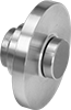
Compact Flange-Mount Check Valves
316 Stainless Steel Body—Spring-Loaded Piston
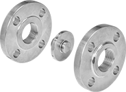 |  |
Shown with Flanges (Not Included) |
Flow Coefficient (Cv)—Flow coefficient (Cv) is the amount of water (in gallons per minute) at 60° F that will flow through a fully open valve with a difference of 1 psi between the inlet and the outlet.
Pipe Size | Flow Coefficient (Cv) | Max. Pressure @ Temp. | Min. Opening Pressure, psi | Temp. Range, ° F | End-to-End Lg. | Mounting Position | For Flange Class | For Use With | Piston Material | Spring Material | Seal Material | Each | |||
|---|---|---|---|---|---|---|---|---|---|---|---|---|---|---|---|
Flanged × Flanged | |||||||||||||||
| 1/2 | 2.4 | 720 psi @ 100° F | 0.5 | -10 to 400 | 1/4" | Any Angle, Horizontal, Vertical | 150, 300 | Air, Argon, Helium, Krypton, Neon, Water, Xenon | 316 Stainless Steel | 316 Stainless Steel | Viton® Fluoroelastomer | 1969N11 | 0000000 | ||
| 3/4 | 4.4 | 720 psi @ 100° F | 0.5 | -10 to 400 | 1/4" | Any Angle, Horizontal, Vertical | 150, 300 | Air, Argon, Helium, Krypton, Neon, Water, Xenon | 316 Stainless Steel | 316 Stainless Steel | Viton® Fluoroelastomer | 1969N12 | 000000 | ||
| 1 | 6.1 | 720 psi @ 100° F | 0.5 | -10 to 400 | 1/4" | Any Angle, Horizontal, Vertical | 150, 300 | Air, Argon, Helium, Krypton, Neon, Water, Xenon | 316 Stainless Steel | 316 Stainless Steel | Viton® Fluoroelastomer | 1969N13 | 000000 | ||
| 1 1/4 | 12.7 | 720 psi @ 100° F | 0.5 | -10 to 400 | 1/4" | Any Angle, Horizontal, Vertical | 150, 300 | Air, Argon, Helium, Krypton, Neon, Water, Xenon | 316 Stainless Steel | 316 Stainless Steel | Viton® Fluoroelastomer | 1969N14 | 000000 | ||
| 1 1/2 | 18.8 | 720 psi @ 100° F | 0.5 | -10 to 400 | 1/4" | Any Angle, Horizontal, Vertical | 150, 300 | Air, Argon, Helium, Krypton, Neon, Water, Xenon | 316 Stainless Steel | 316 Stainless Steel | Viton® Fluoroelastomer | 1969N15 | 000000 | ||
| 2 | 32 | 720 psi @ 100° F | 0.5 | -10 to 400 | 1/4" | Any Angle, Horizontal, Vertical | 150, 300 | Air, Argon, Helium, Krypton, Neon, Water, Xenon | 316 Stainless Steel | 316 Stainless Steel | Viton® Fluoroelastomer | 1969N16 | 000000 | ||
| 3 | 89 | 720 psi @ 100° F | 0.5 | -10 to 400 | 5/16" | Any Angle, Horizontal, Vertical | 150, 300 | Air, Argon, Helium, Krypton, Neon, Water, Xenon | 316 Stainless Steel | 316 Stainless Steel | Viton® Fluoroelastomer | 1969N18 | 000000 | ||
| 4 | 144 | 720 psi @ 100° F | 0.5 | -10 to 400 | 3/8" | Any Angle, Horizontal, Vertical | 150, 300 | Air, Argon, Helium, Krypton, Neon, Water, Xenon | 316 Stainless Steel | 316 Stainless Steel | Viton® Fluoroelastomer | 1969N19 | 000000 | ||
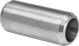
Butt-Weld Check Valves
316 Stainless Steel Body—Spring-Loaded Piston
 |
Flow Coefficient (Cv)—Flow coefficient (Cv) is the amount of water (in gallons per minute) at 60° F that will flow through a fully open valve with a difference of 1 psi between the inlet and the outlet.
Pipe Size | For Pipe Schedule | Flow Coefficient (Cv) | Max. Pressure @ Temp. | Min. Opening Pressure, psi | Temp. Range, ° F | End-to-End Lg. | Mounting Position | Specs. Met | For Use With | Piston Material | Spring Material | Seal Material | Each | |||
|---|---|---|---|---|---|---|---|---|---|---|---|---|---|---|---|---|
Butt Weld × Butt Weld | ||||||||||||||||
| 1/2 | 40 | 2.4 | 1,500 psi @ 100° F | 0.5 | -10 to 400 | 2 3/16" | Any Angle, Horizontal, Vertical | ASME B16.25 | Air, Argon, Helium, Krypton, Neon, Water, Xenon | 316 Stainless Steel | 316 Stainless Steel | Viton® Fluoroelastomer | 1971N11 | 0000000 | ||
| 3/4 | 40 | 4.4 | 1,500 psi @ 100° F | 0.5 | -10 to 400 | 2 11/16" | Any Angle, Horizontal, Vertical | ASME B16.25 | Air, Argon, Helium, Krypton, Neon, Water, Xenon | 316 Stainless Steel | 316 Stainless Steel | Viton® Fluoroelastomer | 1971N12 | 000000 | ||
| 1 | 40 | 6.1 | 1,500 psi @ 100° F | 0.5 | -10 to 400 | 2 15/16" | Any Angle, Horizontal, Vertical | ASME B16.25 | Air, Argon, Helium, Krypton, Neon, Water, Xenon | 316 Stainless Steel | 316 Stainless Steel | Viton® Fluoroelastomer | 1971N13 | 000000 | ||
| 1 1/2 | 40 | 18.8 | 1,500 psi @ 100° F | 0.5 | -10 to 400 | 3 15/16" | Any Angle, Horizontal, Vertical | ASME B16.25 | Air, Argon, Helium, Krypton, Neon, Water, Xenon | 316 Stainless Steel | 316 Stainless Steel | Viton® Fluoroelastomer | 1971N15 | 000000 | ||
| 2 | 40 | 32 | 1,500 psi @ 100° F | 0.5 | -10 to 400 | 4 3/8" | Any Angle, Horizontal, Vertical | ASME B16.25 | Air, Argon, Helium, Krypton, Neon, Water, Xenon | 316 Stainless Steel | 316 Stainless Steel | Viton® Fluoroelastomer | 1971N16 | 000000 | ||
