About Actuated On/Off Valves
More
Threaded Balancing Valves

- Valve Type: Ball
- For Use With: Water
- Seal Material: EPDM Rubber
- Specifications Met: CSA Certified
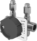
Thread these balancing valves onto pipe—they help you measure the pressure differential across the valve as well as change the flow rate to components in your system. Sometimes called circuit setters, they’re used in HVAC systems and other systems that require even flow distribution. To see what percentage they’re open, there’s an arrow on these valves that’s connected to their measuring plate. Readout ports on both sides let you attach flow measurement tools, such as pressure gauges and probes, which help you track how much the valves reduce flow. Open these valves to a saved percentage by using their memory shutoff function.
Flow coefficient (Cv) is the amount of water (in gallons per minute) at 60° F that will flow through a fully open valve with a difference of 1 psi between the inlet and the outlet.
| Pipe Size | Flow Coefficient (Cv) | Maximum Pressure | Temperature Range, °F | End-to-End Length | Each | |
Brass Body | ||||||
|---|---|---|---|---|---|---|
NPT Female × NPT Female | ||||||
| 1/2 | 1.52 | 400 psi @ 250° F | 0° to 250° | 3" | 0000000 | 0000000 |
| 3/4 | 2.75 | 400 psi @ 250° F | 0° to 250° | 3 1/16" | 0000000 | 000000 |
| 1 | 5.75 | 400 psi @ 250° F | 0° to 250° | 3 13/16" | 0000000 | 000000 |
| 1 1/4 | 12.5 | 400 psi @ 250° F | 0° to 250° | 4 7/16" | 0000000 | 000000 |
| 1 1/2 | 19.9 | 400 psi @ 250° F | 0° to 250° | 4 7/16" | 0000000 | 000000 |
| 2 | 40 | 400 psi @ 250° F | 0° to 250° | 5 3/16" | 0000000 | 000000 |
| 2 1/2 | 65 | 400 psi @ 250° F | 0° to 250° | 6" | 0000000 | 000000 |
| 3 | 112 | 400 psi @ 250° F | 0° to 250° | 6 1/2" | 0000000 | 00000000 |
Solder-Connect Balancing Valves

- Valve Type: Ball
- For Use With: Water
- Seal Material: EPDM Rubber
- Specifications Met: CSA Certified
Attach these balancing valves using solder—they help you measure the difference in pressure across the valve and adjust the flow rate to system components. Also known as circuit setters, they’re often used in systems that need an even distribution of flow, such as HVAC systems. To check what percentage they’re open, there’s an arrow on these valves that’s connected to their measuring plate. There are readout ports on both sides for connecting flow measurement tools, such as pressure gauges and probes, which help you track how much the valves reduce flow. Use the memory shutoff function to open them to a saved setting.
Flow coefficient (Cv) is the amount of water (in gallons per minute) at 60° F that will flow through a fully open valve with a difference of 1 psi between the inlet and the outlet.
| For Tube OD | Flow Coefficient (Cv) | Maximum Pressure | Temperature Range, °F | End-to-End Length | Stem Type | Each | |
Brass Body | |||||||
|---|---|---|---|---|---|---|---|
Solder Connect × Solder Connect | |||||||
| 1/2" | 1.75 | 200 psi @ 250° F, 250 psi @ 225° F, 300 psi @ 200° F | 0° to 250° | 2 15/16" | Nonrising | 0000000 | 0000000 |
| 3/4" | 3.4 | 200 psi @ 250° F, 250 psi @ 225° F, 300 psi @ 200° F | 0° to 250° | 3 9/16" | Nonrising | 0000000 | 000000 |
| 1" | 5.75 | 200 psi @ 250° F, 250 psi @ 225° F, 300 psi @ 200° F | 0° to 250° | 4 5/16" | Nonrising | 0000000 | 000000 |
Motor-Driven On/Off Valves with Solder-Connect Fittings

- Valve Type: Ball
- For Use With: Water, Steam
- Seal Material : Buna-N Rubber
- Specifications Met: C-UL Listed, UL Listed
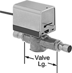
Slide copper pipe into the solder-connect fittings on these valves and weld for a strong, permanent connection. They’re often used for remote on/off control in heating and cooling systems. All operate on electricity to automatically start and stop flow. Valves do not require a minimum pressure drop between the inlet and the outlet for operation. They are normally closed unless actuated. All are standard port, so they slightly restrict flow.
The actuator is directly mounted to the valve body to minimize movement and reduce wear. The manual override allows you to operate the valve during power outages.
Flow coefficient (Cv) is the amount of water (in gallons per minute) at 60° F that will flow through a fully open valve with a difference of 1 psi between the inlet and the outlet.
Overall | ||||||||||||
|---|---|---|---|---|---|---|---|---|---|---|---|---|
| For Tube OD | For Copper Tube Size | Flow Coefficient (Cv) | Max. Pressure | Max. Steam Pressure | Pressure Drop | Actuation Time, sec. | Temp. Range, °F | Valve Lg. | Lg. | Ht. | Each | |
Brass Body with Wire Leads | ||||||||||||
24V AC | ||||||||||||
| 5/8" | 1/2 | 4 | 300 psi @ 250° F | 15 psi @ 250° F | Zero Pressure Drop | 9 | 35° to 250° | 3 1/2" | 3 11/16" | 4 1/4" | 00000000 | 0000000 |
| 7/8" | 3/4 | 4 | 300 psi @ 250° F | 15 psi @ 250° F | Zero Pressure Drop | 9 | 35° to 250° | 3 1/2" | 3 11/16" | 4 1/4" | 00000000 | 000000 |
| 1 1/8" | 1 | 4 | 300 psi @ 250° F | 15 psi @ 250° F | Zero Pressure Drop | 9 | 35° to 250° | 3 1/2" | 3 11/16" | 4 1/4" | 00000000 | 000000 |
120V AC | ||||||||||||
| 5/8" | 1/2 | 3 | 300 psi @ 250° F | 15 psi @ 250° F | Zero Pressure Drop | 9 | 35° to 250° | 3 1/2" | 3 11/16" | 4 1/4" | 00000000 | 000000 |
| 7/8" | 3/4 | 3 | 300 psi @ 250° F | 15 psi @ 250° F | Zero Pressure Drop | 9 | 35° to 250° | 3 1/2" | 3 11/16" | 4 1/4" | 00000000 | 000000 |
| 1 1/8" | 1 | 3 | 300 psi @ 250° F | 15 psi @ 250° F | Zero Pressure Drop | 9 | 35° to 250° | 3 1/2" | 3 11/16" | 4 1/4" | 00000000 | 000000 |
Air-Release Valves for Oil and Fuel

- Max. Pressure: 400 psi
- Temperature Range: -20° to 500° F
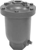
Use this valve to eliminate air pockets in systems for oil, diesel fuel, gasoline, and kerosene. Valve has a vented relief port to exhaust discharge directly. Body is 304 stainless steel for excellent corrosion resistance.
Inlet | Relief Port | |||||
|---|---|---|---|---|---|---|
| Pipe Size | Location | Pipe Size | Location | Overall Ht. | Each | |
NPT Female Inlet and Relief Port | ||||||
304 Stainless Steel Body | ||||||
| 3/4 | Bottom | 1/2 | Top | 7" | 0000000 | 0000000 |
Air-Release Valves for Water and Coolant


and Female
Outlet

These valves are often used to remove air pockets in cooling and heating systems to maintain consistent flow and prevent water surges that can damage equipment. All have a vented relief port to exhaust discharge directly.
Valves with female/male inlets have an inlet with both male and female threads, so they can be connected to both male and female adapters and equipment ports.
Inlet | Outlet | ||||||||
|---|---|---|---|---|---|---|---|---|---|
| Pipe Size | Location | Pipe Size | Location | Relief Port Location | Max. Pressure, psi | Temperature Range, °F | Overall Ht. | Each | |
Brass Body—Vertical Mount | |||||||||
| 1/8 | Bottom | 1/8 | Side | Top | 75 | 33° to 240° | 4 3/8" | 000000 | 000000 |
Inlet | ||||||||
|---|---|---|---|---|---|---|---|---|
| Female Pipe Size | Male Pipe Size | Location | Relief Port Location | Max. Pressure, psi | Temperature Range, °F | Overall Ht. | Each | |
Brass Body—Vertical Mount | ||||||||
| 1/2 | 3/4 | Bottom | Top | 150 | 33° to 240° | 4 3/4" | 000000 | 000000 |
Inlet | |||||||
|---|---|---|---|---|---|---|---|
| Pipe Size | Location | Relief Port Location | Max. Pressure, psi | Temperature Range, °F | Overall Ht. | Each | |
Brass Body—Vertical Mount | |||||||
| 1/8 | Bottom | Top | 50 | 33° to 240° | 2 5/8" | 0000000 | 000000 |
| 1/8 | Bottom | Top | 50 | 33° to 240° | 3 3/4" | 0000000 | 00000 |
| 1/8 | Bottom | Top | 75 | 33° to 240° | 4 3/8" | 000000 | 00000 |
| 1/4 | Bottom | Top | 50 | 33° to 240° | 4" | 0000000 | 00000 |
| 1/4 | Bottom | Top | 150 | 33° to 240° | 4 3/4" | 000000 | 00000 |
| 1/2 | Bottom | Top | 150 | 33° to 240° | 3 3/8" | 0000000 | 00000 |
| 3/4 | Bottom | Top | 150 | 33° to 240° | 3 3/8" | 0000000 | 00000 |
| 1 | Bottom | Top | 150 | 33° to 240° | 3 1/2" | 0000000 | 00000 |
Corrosion-Resistant Remote-Discharge Air-Release Valves for Water

For excellent corrosion resistance in wet conditions and harsh environments, these valves have no metal parts. They eliminate air pockets to maintain consistent flow and prevent water surges that can damage equipment. All have a threaded relief port that can be attached to a drain line for remote discharge.
Inlet | Relief Port | |||||||
|---|---|---|---|---|---|---|---|---|
| Pipe Size | Location | Pipe Size | Location | Max. Pressure, psi | Temperature Range, °F | Overall Ht. | Each | |
NPT Female Inlet and Relief Port | ||||||||
PVC Body | ||||||||
| 1/2 | Bottom | 1/2 | Top | 150 | 32° to 140° | 3" | 00000000 | 000000 |
| 3/4 | Bottom | 3/4 | Top | 150 | 32° to 140° | 3 1/2" | 00000000 | 00000 |
| 1 | Bottom | 1 | Top | 150 | 32° to 140° | 3 7/8" | 00000000 | 00000 |
| 1 1/4 | Bottom | 1 1/4 | Top | 150 | 32° to 140° | 4 1/2" | 00000000 | 00000 |
| 2 | Bottom | 2 | Top | 150 | 32° to 140° | 5 3/4" | 00000000 | 000000 |
Remote-Discharge Air-Release Valves for Water

- Max. Pressure: See table
- Temperature Range: 32° to 150° F
Unlike valves that release discharge directly, these have a threaded relief port to direct discharge away from your work environment. Often used to increase pump efficiency, they eliminate air pockets in your system to maintain consistent flow and prevent water surges that can damage equipment.
Inlet | Relief Port | ||||||
|---|---|---|---|---|---|---|---|
| Pipe Size | Location | Pipe Size | Location | Max. Pressure, psi | Overall Ht. | Each | |
NPT Female Inlet and Relief Port | |||||||
Cast Iron Body | |||||||
| 3/8 | Bottom | 3/8 | Top | 150 | 5 3/4" | 00000000 | 0000000 |
| 1/2 | Bottom | 3/8 | Top | 150 | 5 3/4" | 00000000 | 000000 |
| 3/4 | Bottom | 3/8 | Top | 150 | 5 3/4" | 00000000 | 000000 |
| 1 | Bottom | 3/8 | Top | 150 | 5 3/4" | 00000000 | 000000 |
Ductile Iron Body | |||||||
| 1/2 | Bottom | 1/2 | Top | 300 | 5 1/2" | 00000000 | 000000 |
| 3/4 | Bottom | 1/2 | Top | 300 | 5 1/2" | 00000000 | 000000 |
| 1 | Bottom | 1/2 | Top | 150 | 9" | 00000000 | 000000 |
| 1 | Bottom | 1/2 | Top | 300 | 5 1/2" | 00000000 | 000000 |
| 2 | Bottom | 1/2 | Top | 150 | 9" | 00000000 | 000000 |
| 2 | Bottom | 1/2 | Top | 150 | 10 1/2" | 00000000 | 000000 |
Corrosion-Resistant Air-Release Valves for Water and Coolant

- Max. Pressure: 90 psi
- Temperature Range: See table
These valves are made of corrosion-resistant materials for use in wet conditions and harsh environments. They eliminate air pockets to maintain consistent flow and prevent water surges that can damage equipment. All have a vented relief port to exhaust discharge directly.
Valve with a Buna-N seal is for use in heating and cooling systems.
Valve with an EPDM seal is for use in cooling systems only.
Inline Air-Release Valves for Water

- Max. Pressure: 125 psi
- Temperature Range: 40° to 240° F
Eliminate air pockets without stopping flow—these valves have an internal wire brush that traps air bubbles and discharges them through the top relief port while allowing inline flow from the inlet to the outlet. They are often used to increase efficiency in heating and cooling systems. The vented relief port exhausts discharge directly. Valves have a durable bronze body for a long service life.
Key-Operated Air-Release Valves for Water
- Max. Pressure: 150 psi
- Temperature Range: 33° to 200° F
Turn the key to manually release air from radiators, heaters, and other hot water equipment. These valves have a vented relief port that exhausts discharge directly. Body is nickel-plated brass for good corrosion resistance.
Air-Release Valves for Drinking Water

- Max. Pressure: 300 psi
- Temperature Range: 33° to 225° F
Eliminate air pockets in your drinking water system with these valves. They meet NSF/ANSI 61, which designates them as safe to use with drinking water. They have a vented relief port to exhaust discharge directly.
Air-Release Valves for Steam

Our only air-release valves for steam, these seal shut when steam enters the valve to prevent system contents from escaping through the relief port. They are commonly used to eliminate air pockets in steam mains and risers. They exhaust discharge directly through the vented relief port.
Inlet | |||||||
|---|---|---|---|---|---|---|---|
| Max. Steam Pressure, psi | Pipe Size | Location | Relief Port Location | Temperature Range, °F | Overall Ht. | Each | |
NPT Male Inlet and Relief Vent | |||||||
Brass Body | |||||||
| 15 | 3/4 | Bottom | Top | --° to 250° | 3 1/2" | 0000000 | 000000 |


