Selecting Compatible Lead Screws and Nuts
More
About Ball and Roller Bearings
More
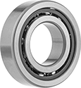
Angular-Contact Thrust Ball Bearings

Single-row bearings handle thrust loads on one side. For applications with thrust loads on both sides, mount them in pairs.
Open bearings dissipate heat more efficiently than shielded and sealed bearings.
Combined Load Cap., lbs. | |||||||||||||
|---|---|---|---|---|---|---|---|---|---|---|---|---|---|
| Bearing Trade Number | For Shaft Dia., mm | For Housing ID, mm | Wd., mm | Ring Material | Dynamic | Static | Max. Speed, rpm | Lubrication | Contact Angle | Temp. Range, °F | ABEC Rating | Each | |
Single Row | |||||||||||||
Open | |||||||||||||
| 7205 | 25 | 52 | 15 | Steel | 3,300 | 2,050 | 15,000 | Required | 40° | -40° to 300° | ABEC-3 | 0000000 | 000000 |
High-Speed Angular-Contact Thrust Ball Bearings

An ABEC-7 rating means these bearings are made to some of the tightest tolerances, so they operate at the highest speeds.
Open bearings dissipate heat more efficiently than sealed bearings.
Combined Load Cap., lbs. | |||||||||||||
|---|---|---|---|---|---|---|---|---|---|---|---|---|---|
| Bearing Trade Number | For Shaft Dia., mm | For Housing ID, mm | Wd., mm | Ring Material | Dynamic | Static | Max. Speed, rpm | Lubrication | Contact Angle | Temp. Range, °F | ABEC Rating | Each | |
Single Row | |||||||||||||
Open | |||||||||||||
| 7205 | 25 | 52 | 15 | Steel | 3,900 | 2,250 | 29,900 | Required | 15° | -40° to 245° | ABEC-7 | 0000000 | 0000000 |
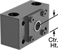
End Supports for Lead Screws and Ball Screws
A set of ball bearings reduces friction and secures the end of a ball or lead screw. Note: The end of your ball or lead screw must be machined before installing it into an end support.

End supports for combined radial and thrust loads handle radial loads (perpendicular to the lead screw) and thrust loads (parallel to the lead screw).
Combined Load Cap., lbs. | Face Mounting Holes | Top Mounting Holes | |||||||||||||
|---|---|---|---|---|---|---|---|---|---|---|---|---|---|---|---|
| ID | Ht. | Center Ht. | Wd. | Dp. | Static | Dynamic | No. of Mounting Holes | Dia. | Ctr.-to-Ctr. Wd. | Ctr.-to-Ctr. Ht. | Dia. | Ctr.-to-Ctr. Wd. | Temperature Range, °F | Each | |
Alloy Steel | |||||||||||||||
| 63/64" | 3 3/8" | 1 3/4" | 6" | 2 29/32" | 3,750 | 2,100 | 6 | 21/32" | 4 1/4" | 2" | 29/32" | 4 1/4" | -40° to 210° | 00000000 | 000000000 |


