


Filter by
System of Measurement
ID
Roller Bearing Type
For Load Direction

Shaft Mount Type


Bearing Construction
Bearing Seal Type

Material
Plain Bearing Type
Lubrication
Ball Material
DFARS Specialty Metals
Export Control Classification Number (ECCN)
Maximum Temperature
Minimum Temperature
Needle-Roller Bearings
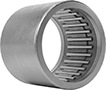 |
Also known as drawn-cup roller bearings, these are our thinnest roller bearings. The outer ring is drawn out to form a lip that holds the bearing together. Bearings take on the shape of their housing and may be oblong prior to installation.
Open Bearing—Open bearings dissipate heat more efficiently than sealed bearings.
Radial Load Cap., lb. | |||||||||||||
|---|---|---|---|---|---|---|---|---|---|---|---|---|---|
For Shaft Dia., mm | For Housing ID, mm | Wd., mm | Dynamic | Static | Max. Rotation Speed, rpm | Lubrication | For Shaft Surface Smoothness, Ra, μin | Temp. Range, ° F | Specs. Met | Each | |||
For Radial Load—Open with Steel Ring | |||||||||||||
| 13 | 19 | 12 | 1,500 | 1,750 | 18,700 | Required | 8 | -20 to 280 | DIN 618, ISO 3245 | 5905K531 | 000000 | ||
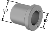
Dry-Running Sleeve Bearings
 |
Made of naturally slippery plastic so you’ll never have to add lubricant. They’re ideal for clean environments where you need to prevent oil drips or graphite flakes. Compared to metal bearings, they are lighter and will never rust.
With no moving parts, sleeve bearings are the simplest way to support the load of a rotating shaft while reducing friction. Also known as plain bearings.
Nylon—The most popular choice, nylon is wear resistant yet economical. Keep in mind, though, that it will swell and weaken when exposed to moisture.
Each | |||||||||||
|---|---|---|---|---|---|---|---|---|---|---|---|
For Shaft Dia., mm | For Housing ID, mm | Lg., mm | Dynamic Radial Load Cap. @ Speed | Color | Temp. Range, ° F | 1-24 | 25-99 | 100-Up | |||
Nylon | |||||||||||
| 13 | 16 | 16 | 100 lb. @ 60 rpm | Off-White | -10 to 220 | 6389K773 | 000000 | 000000 | 000000 | ||
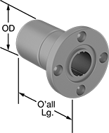
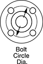
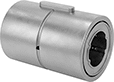
Mounted Linear Bearings for Ball Splines
 |
A flange with mounting holes makes it easy to attach a load to these bearings. Create a compact linear and rotary motion system for robots and other applications requiring complex, fast movements, by combining them with ball splines. These bearings move smoothly and precisely even at high speeds along ball splines while grooves on the ball spline transmit rotary power. Clip a retaining ring (not included) into the groove on these bearings to position them in your system.
Steel Bearings
 |  |  |
For 4 Splines |
Groove, mm | ||||||||||||||||||
|---|---|---|---|---|---|---|---|---|---|---|---|---|---|---|---|---|---|---|
For Spline Dia., mm | For No. of Splines | Overall Lg., mm | Flange OD, mm | Bolt Circle Dia., mm | OD, mm | Dynamic Load Cap., lb. | Static Load Cap., lb. | Max. Dynamic Torque, in·lbf | Max. Static Torque, in·lbf | Max. Temp., ° F | With Retaining Ring Grooves | Wd. | Dia. | No. of Mounting Holes | Each | |||
| 13 | 4 | 36 | 43 | 33 | 24 | 600 | 1,050 | 185 | 346 | 176 | Yes | 1.3 | 22.7 | 4 | 61145K111 | 000000 | ||
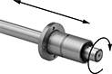
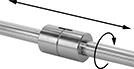
Quick-Disconnect (QD) Bushings
 |  |
Machinable Shaft Mount |
The screw connections on these bushings easily mate to compatible quick-disconnect sprockets and pulleys. Bushings fit quick-disconnect (QD) sprockets and pulleys of the same bushing trade number. As you tighten the included screws, the bushing grips the shaft and pulls it into the sprocket or pulley.
304 Stainless Steel—304 stainless steel bushings resist corrosion from washdowns and humidity, so they’re common in food-processing plants and other frequently-cleaned areas. You can machine the center of these bushings to fit the exact dimensions of your shaft.
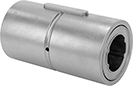
Linear Bearings for Ball Splines
 |
Combine these bearings with a ball spline to create a compact linear and rotary motion system for applications with fast, complex movements, such as robotics. These bearings move smoothly and precisely even at high speeds along ball splines while grooves on the ball spline transmit rotary power. Clip a retaining ring into the groove on these bearings to position them in your system. Use the keyway and included machine key for attaching your load.
Steel Bearings
 | |
For 4 Splines |
Groove, mm | Keyway, mm | ||||||||||||||||||
|---|---|---|---|---|---|---|---|---|---|---|---|---|---|---|---|---|---|---|---|
For Spline Dia., mm | For No. of Splines | Overall Lg., mm | OD, mm | Dynamic Load Cap., lb. | Static Load Cap., lb. | Max. Dynamic Torque, in·lbf | Max. Static Torque, in·lbf | Max. Temp., ° F | With Retaining Ring Grooves | Wd. | Dia. | Includes | Lg. | Wd. | Dp. | Each | |||
| 13 | 4 | 36 | 24 | 600 | 1,050 | 185 | 346 | 176 | Yes | 1.3 | 22.7 | Machine Key | 15 | 3 | 1.5 | 61145K12 | 000000 | ||
Stainless Steel Bearings
 | |
For 4 Splines |
Groove, mm | Keyway, mm | ||||||||||||||||||
|---|---|---|---|---|---|---|---|---|---|---|---|---|---|---|---|---|---|---|---|
For Spline Dia., mm | For No. of Splines | Overall Lg., mm | OD, mm | Dynamic Load Cap., lb. | Static Load Cap., lb. | Max. Dynamic Torque, in·lbf | Max. Static Torque, in·lbf | Max. Temp., ° F | With Retaining Ring Grooves | Wd. | Dia. | Includes | Lg. | Wd. | Dp. | Each | |||
| 13 | 4 | 36 | 24 | 600 | 1,050 | 185 | 346 | 176 | Yes | 1.3 | 22.7 | Machine Key | 15 | 3 | 1.5 | 61145K26 | 0000000 | ||
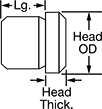
Metric Press-Fit Drill Bushings with Head
 |  |
 |  |
Shown in Countersunk Hole | Shown in Standard Hole |
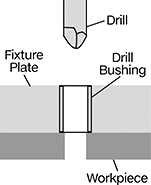
Even under extreme drilling pressure, these metric bushings won't press through your jig plate. They’re ANSI Type H bushings, also known as headed bushings. A flanged head acts as a stop, so these bushings won’t move as you push down your drill bit, reamer, or other cutting bit. Use them even in jigs made of thin or soft materials—the head adds support to protect your jig from damage caused by heavy use. Drill bushings ensure accurate, consistent cuts and drilled holes from one part to the next. They’re also used as spacers, shims, and machinery bushings. Made of hardened, ground steel, these bushings hold their shape and resist wear, so they last for many cycles without needing to be replaced.
These bushings meet DIN 172 dimensional standards. This standard is no longer active, but it’s often used as a reference point for making sure parts are compatible with other parts and tools.
To install, fit the bushing into a hole in your jig. In a standard hole, the head will sit above the jig plate; to mount flush, install in a countersunk hole. A chamfered edge on the bottom of the bushing helps center the bushing in the hole. Once it’s centered, press the bushing into the hole with a hydraulic or lever press.
Head, mm | Tolerance, mm | Each | ||||||||||||||||
|---|---|---|---|---|---|---|---|---|---|---|---|---|---|---|---|---|---|---|
OD, mm | Lg., mm | For Drill Bit Size, mm | For Drill Bit Size Decimal Equiv. | OD | Thk. | ID | OD | Lg. | Drill Bushing Type | Material | Hardness | Specs. Met | 1-5 | 6-11 | 12-Up | |||
13 mm ID | ||||||||||||||||||
| 22 | 12 | 13 | 0.5118" | 26 | 4 | 0.016 to 0.034 | 0.015 to 0.028 | -0.2 to 0.2 | H | Steel | Rockwell C61 | DIN 172 | 96977A450 | 000000 | 000000 | 000000 | ||
| 22 | 24 | 13 | 0.5118" | 26 | 4 | 0.016 to 0.034 | 0.015 to 0.028 | -0.2 to 0.2 | H | Steel | Rockwell C61 | DIN 172 | 96977A451 | 00000 | 00000 | 00000 | ||
| 22 | 32 | 13 | 0.5118" | 26 | 4 | 0.016 to 0.034 | 0.015 to 0.028 | -0.3 to 0.3 | H | Steel | Rockwell C61 | DIN 172 | 96977A452 | 00000 | 00000 | 00000 | ||
Metric Press-Fit Drill Bushings
 |
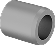 |
Also known as jig bushings, these metric drill bushings fit inside fixture plate holes to precisely guide drill bits, counterbores, reamers, and other cutting tools. They improve accuracy so that your drilled holes and cuts are consistent from part to part. Known for their versatility, drill bushings are also used as spacers, shims, and machinery bushings. These bushings are made of hardened, ground steel that holds its shape and resists wear, so they last for many cycles without needing to be replaced.
All bushings have a chamfer on the outside that centers the bushing as you place it into the hole. Press into place with a manual or hydraulic press. Since the bushing is sized slightly larger than the hole for an extremely tight fit, it’ll stay put permanently. These are ANSI Type PM bushings—also known as headless bushings—which means you don’t need to counterbore the hole to mount them flush.
They also have an internal chamfer that makes it easy to insert bits, pins, and punches without damaging the bushing or misaligning tools.
Don't see the size you need? Additional sizes are available.
Both Ends—Bushings with an internal chamfer on both ends allow you to insert tools no matter which end of the bushing is inserted into the jig. However, having an internal chamfer on the bottom of your bushing may cause shavings to get caught and bind as you remove the bit.
DIN 179—DIN 179 bushings meet dimensional and material standards that make sure they're compatible with other parts and tools. Although DIN 179 is no longer an active standard, it's still a common reference point for designers.
Tolerance, mm | |||||||||||||||
|---|---|---|---|---|---|---|---|---|---|---|---|---|---|---|---|
OD, mm | Lg., mm | Internal Chamfer | For Drill Bit Size, mm | For Drill Bit Size Decimal Equiv. | ID | OD | Lg. | Drill Bushing Type | Material | Hardness | Specs. Met | Each | |||
13 mm ID | |||||||||||||||
| 22 | 16 | One End | 13 | 0.5118" | 0.016 to 0.034 | 0.015 to 0.028 | -0.2 to 0.2 | PM | Steel | Rockwell C61 | DIN 179 | 96990A433 | 000000 | ||
| 22 | 16 | Both Ends | 13 | 0.5118" | 0.016 to 0.034 | 0.015 to 0.028 | -0.2 to 0.2 | PM | Steel | Rockwell C61 | — | 97060A401 | 00000 | ||
| 22 | 28 | One End | 13 | 0.5118" | 0.016 to 0.034 | 0.015 to 0.028 | -0.2 to 0.2 | PM | Steel | Rockwell C61 | DIN 179 | 8486A561 | 00000 | ||
| 22 | 28 | Both Ends | 13 | 0.5118" | 0.016 to 0.034 | 0.015 to 0.028 | -0.2 to 0.2 | PM | Steel | Rockwell C61 | — | 97060A402 | 00000 | ||
