


Filter by
System of Measurement
Shaft Diameter
ID

Bearing Seal Type

Ball Material
Ball Bearing Profile
For Load Direction


Plain Bearing Type

Lubrication
Thickness
Flange Thickness
DFARS Specialty Metals
Thrust Ball Bearings
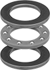 | |
For silky-smooth motion, the balls inside these bearings roll nearly friction-free. You'll often find them at the end of a shaft or between a stationary and rotating surface, such as on a propeller or rotary table.
These bearings come as three separate pieces—one cage and two washers. The cage holds the balls in place, while the washers create a surface for the balls to roll on. This design is easy to lubricate, but the oil will attract dust and grime since it's exposed.
Steel—Strong and wear resistant. However, these bearings are best for dry environments since moisture will cause them to rust.
For Shaft Dia., mm | OD, mm | Thk., mm | Cage Material | Dynamic Thrust Load Cap., lb. | Max. Rotation Speed, rpm | Temp. Range, ° F | Includes | Each | |||
|---|---|---|---|---|---|---|---|---|---|---|---|
Steel | |||||||||||
| 19 | 32 | 8.74 | Nylon | 290 | 5,000 | -40 to 220 | Two Washers | 6655K58 | 00000 | ||
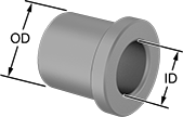
Dry-Running Flanged Sleeve Bearings
 |
Made of naturally slippery plastic so you’ll never have to add lubricant. They’re ideal for clean environments where you need to prevent oil drips or graphite flakes. Compared to metal bearings, they are lighter and will never rust.
Flanged sleeve bearings combine a sleeve and thrust bearing in one. The flange supports thrust loads and prevents the bearing from being pushed out of place. The sleeve is the simplest way to support the load of a rotating shaft while reducing friction. Also known as plain bearings.
Moisture-Resistant Ultra-Low-Friction Plastic Blend—These bearings won't warp or swell from humidity or direct contact with water. They glide effortlessly for applications with frequent starts and stops, such as conveyor systems.
For Shaft Dia., mm | For Housing ID, mm | Lg., mm | Flange OD, mm | Flange Thk., mm | Dynamic Radial Load Cap. @ Speed | Dynamic Thrust Load Cap. @ Speed | Color | Temp. Range, ° F | Each | |||
|---|---|---|---|---|---|---|---|---|---|---|---|---|
Moisture-Resistant Ultra-Low-Friction Plastic Blend | ||||||||||||
| 19 | 22 | 23 | 26 | 1 | 550 lb. @ 60 rpm | 230 lb. @ 60 rpm | Yellow | -50 to 190 | 2705T163 | 00000 | ||
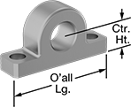
Ready-Mount Bearing Housings with Base Mount
Flanged Screw-Clamp Bushings
 |  |
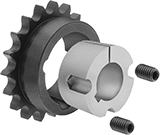
A mounting flange prevents movement during tightening. These bushings are good for shock loads. When you tighten the included screws, the bushing's inner sleeve contracts onto the shaft and the outer sleeve expands to hold your sprocket, pulley, or gear. They can be mounted on shafts with or without keyways.
For Shaft Dia., mm | OD, mm | Overall Wd., mm | Max. Torque, in·lbf | Fastener Tightening Torque, in·lbf | Includes | Each | |||
|---|---|---|---|---|---|---|---|---|---|
Steel | |||||||||
| 19 | 33 | 24 | 1,050 | 42 | Clamping Screws | 1058K73 | 000000 | ||
Corrosion-Resistant Flanged Screw-Clamp Bushings
 |  |
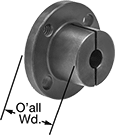
Made from stainless steel or plated with nickel, these bushings resist corrosion. A mounting flange prevents movement during tightening. As screw-clamp bushings, they're good for shock loads. When you tighten the clamping screws, the bushing's inner sleeve tightens onto the shaft and the outer sleeve expands to hold your sprocket, pulley, or gear.
Nickel-Plated Steel—Nickel-plated steel bushings have good corrosion resistance in wet environments. However, the plating may begin to flake with long-term use.
Stainless Steel—Stainless steel bushings have excellent corrosion resistance and can withstand prolonged exposure to moisture.
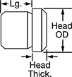
Metric Press-Fit Drill Bushings with Head
 |  |
 |  |
Shown in Countersunk Hole | Shown in Standard Hole |
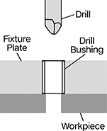
Even under extreme drilling pressure, these metric bushings won't press through your jig plate. They’re ANSI Type H bushings, also known as headed bushings. A flanged head acts as a stop, so these bushings won’t move as you push down your drill bit, reamer, or other cutting bit. Use them even in jigs made of thin or soft materials—the head adds support to protect your jig from damage caused by heavy use. Drill bushings ensure accurate, consistent cuts and drilled holes from one part to the next. They’re also used as spacers, shims, and machinery bushings. Made of hardened, ground steel, these bushings hold their shape and resist wear, so they last for many cycles without needing to be replaced.
These bushings meet DIN 172 dimensional standards. This standard is no longer active, but it’s often used as a reference point for making sure parts are compatible with other parts and tools.
To install, fit the bushing into a hole in your jig. In a standard hole, the head will sit above the jig plate; to mount flush, install in a countersunk hole. A chamfered edge on the bottom of the bushing helps center the bushing in the hole. Once it’s centered, press the bushing into the hole with a hydraulic or lever press.
Head, mm | Tolerance, mm | Each | ||||||||||||||||
|---|---|---|---|---|---|---|---|---|---|---|---|---|---|---|---|---|---|---|
OD, mm | Lg., mm | For Drill Bit Size, mm | For Drill Bit Size Decimal Equiv. | OD | Thk. | ID | OD | Lg. | Drill Bushing Type | Material | Hardness | Specs. Met | 1-5 | 6-11 | 12-Up | |||
19 mm ID | ||||||||||||||||||
| 30 | 15 | 19 | 0.748" | 34 | 5 | 0.02 to 0.041 | 0.015 to 0.028 | -0.2 to 0.2 | H | Steel | Rockwell C61 | DIN 172 | 96977A534 | 000000 | 000000 | 000000 | ||
| 30 | 31 | 19 | 0.748" | 34 | 5 | 0.02 to 0.041 | 0.015 to 0.028 | -0.3 to 0.3 | H | Steel | Rockwell C61 | DIN 172 | 96977A535 | 00000 | 00000 | 00000 | ||
| 30 | 40 | 19 | 0.748" | 34 | 5 | 0.02 to 0.041 | 0.015 to 0.028 | -0.3 to 0.3 | H | Steel | Rockwell C61 | DIN 172 | 96977A536 | 00000 | 00000 | 00000 | ||
Quick-Grip Screw-Clamp Bushings
 |
For Shaft Dia., mm | OD, mm | Overall Wd., mm | Max. Torque, in·lbf | Each | |||
|---|---|---|---|---|---|---|---|
Steel | |||||||
| 19 | 32 | 29 | 2,150 | 2298K66 | 0000000 | ||
Taper-Lock Bushings
 |
Mount these hubless bushings flush into your sprocket or pulley for a slim profile with no protruding screws. They are for use with taper-lock sprockets of the same bushing trade number. As you tighten the included set screws, the bushing grips the shaft and pulls it into your sprocket or pulley.
Split-Tapered Bushings
 |
Steel |
Keyway, mm | |||||||||
|---|---|---|---|---|---|---|---|---|---|
For Shaft Dia., mm | Overall Wd. | Wd. | Dp. | Taper | Fastener Tightening Torque, in·lbf | Each | |||
Steel | |||||||||
Bushing Trade Number H with Clamping Screws | |||||||||
| 19 | 1 1/4" | 6 | 3 | 3° | 95 | 9859T717 | 000000 | ||
Metric Press-Fit Drill Bushings
 |
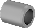 |
Also known as jig bushings, these metric drill bushings fit inside fixture plate holes to precisely guide drill bits, counterbores, reamers, and other cutting tools. They improve accuracy so that your drilled holes and cuts are consistent from part to part. Known for their versatility, drill bushings are also used as spacers, shims, and machinery bushings. These bushings are made of hardened, ground steel that holds its shape and resists wear, so they last for many cycles without needing to be replaced.
All bushings have a chamfer on the outside that centers the bushing as you place it into the hole. Press into place with a manual or hydraulic press. Since the bushing is sized slightly larger than the hole for an extremely tight fit, it’ll stay put permanently. These are ANSI Type PM bushings—also known as headless bushings—which means you don’t need to counterbore the hole to mount them flush.
They also have an internal chamfer that makes it easy to insert bits, pins, and punches without damaging the bushing or misaligning tools.
Don't see the size you need? Additional sizes are available.
Both Ends—Bushings with an internal chamfer on both ends allow you to insert tools no matter which end of the bushing is inserted into the jig. However, having an internal chamfer on the bottom of your bushing may cause shavings to get caught and bind as you remove the bit.
DIN 179—DIN 179 bushings meet dimensional and material standards that make sure they're compatible with other parts and tools. Although DIN 179 is no longer an active standard, it's still a common reference point for designers.
Tolerance, mm | Each | ||||||||||||||||
|---|---|---|---|---|---|---|---|---|---|---|---|---|---|---|---|---|---|
OD, mm | Lg., mm | Internal Chamfer | For Drill Bit Size, mm | For Drill Bit Size Decimal Equiv. | ID | OD | Lg. | Drill Bushing Type | Material | Hardness | Specs. Met | 1-5 | 6-11 | 12-Up | |||
19 mm ID | |||||||||||||||||
| 30 | 20 | One End | 19 | 0.748" | 0.02 to 0.041 | 0.015 to 0.028 | -0.2 to 0.2 | PM | Steel | Rockwell C61 | DIN 179 | 96990A512 | 000000 | 000000 | 000000 | ||
| 30 | 20 | Both Ends | 19 | 0.748" | 0.02 to 0.041 | 0.015 to 0.028 | -0.2 to 0.2 | PM | Steel | Rockwell C61 | — | 97060A494 | 00000 | 00000 | 00000 | ||
