About Gears
More
Low-Profile Right-Angle Speed Reducers
The input and output shafts are positioned at the same height, so these speed reducers take up less than half the vertical space as our standard right-angle speed reducers. Use them to transmit motion at a 90° angle while cutting shaft speed in half and doubling torque. All are permanently lubricated to save maintenance time and effort. Connect to a motor using a shaft coupling (not included).
Radial loads are loads that are perpendicular to the shaft. They’re commonly caused by components attached to shaft, such as pulleys and sprockets.
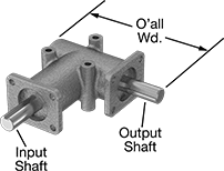
Max. Output | Max. Input | Input Shaft | Output Shaft | Overall | |||||||||||
|---|---|---|---|---|---|---|---|---|---|---|---|---|---|---|---|
| Speed Ratio | Torque | Speed, rpm | Speed, rpm | hp | Dia. | Lg. | Dia. | Lg. | Lg. | Wd. | Ht. | Radial Load Capacity, lbs. | Specifications Met | Each | |
| 2:1 | 8 in.-lbs. @ 1,750 rpm | 1,500 | 3,000 | 0.11 | 3/8" | 0.59" | 3/8" | 0.59" | 3 1/2" | 3" | 1 1/4" | 25 | MIL-I-45208 | 0000000 | 0000000 |
| 2:1 | 24 in.-lbs. @ 1,750 rpm | 1,500 | 3,000 | 0.33 | 5/8" | 1.5" | 5/8" | 1.5" | 6 1/4" | 5" | 2" | 50 | MIL-I-45208 | 0000000 | 000000 |
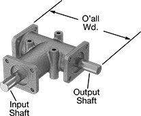
Max. Ouput | Max. Input | Input Shaft | Output Shaft | Overall | |||||||||||
|---|---|---|---|---|---|---|---|---|---|---|---|---|---|---|---|
| Speed Ratio | Torque | Speed, rpm | Speed, rpm | hp | Dia. | Lg. | Dia. | Lg. | Lg. | Wd. | Ht. | Radial Load Capacity, lbs. | Specifications Met | Each | |
| 2:1 | 43 in.-lbs. @ 1,750 rpm | 1,500 | 3,000 | 0.54 | 5/8" | 1.5" | 5/8" | 1.5" | 6" | 5 3/4" | 2" | 50 | MIL-I-45208 | 0000000 | 0000000 |
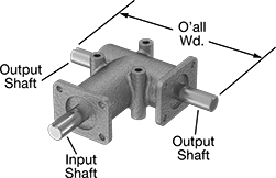
Max. Output | Max. Input | Input Shaft | Output Shaft | Overall | ||||||||||||
|---|---|---|---|---|---|---|---|---|---|---|---|---|---|---|---|---|
| Speed Ratio | Torque | Speed, rpm | Speed, rpm | hp | Dia. | Lg. | Dia. | Left Hand Lg. | Right Hand Lg. | Lg. | Wd. | Ht. | Radial Load Capacity, lbs. | Specifications Met | Each | |
| 2:1 | 24 in.-lbs. @ 1,750 rpm | 1,500 | 3,000 | 0.33 | 5/8" | 1.5" | 5/8" | 1.375" | 1.5" | 6 1/4" | 6 1/2" | 2" | 50 | MIL-I-45208 | 0000000 | 0000000 |
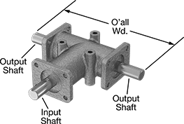
Max. Output | Max. Input | Input Shaft | Output Shaft | Overall | |||||||||||
|---|---|---|---|---|---|---|---|---|---|---|---|---|---|---|---|
| Speed Ratio | Torque | Speed, rpm | Speed, rpm | hp | Dia. | Lg. | Dia. | Lg. | Lg. | Wd. | Ht. | Radial Load Capacity, lbs. | Specifications Met | Each | |
| 2:1 | 43 in.-lbs. @ 1,750 rpm | 1,500 | 3,000 | 0.54 | 5/8" | 1.5" | 5/8" | 1.5" | 6" | 7 1/4" | 2" | 50 | MIL-I-45208 | 0000000 | 0000000 |
Right-Angle Gear Boxes
Transmit rotary motion at a right angle without changing speed or torque. Gear boxes are permanently lubricated to save maintenance time and effort. Connect to a motor using a shaft coupling (not included).
Radial loads are loads that are perpendicular to the shaft. They’re commonly caused by components attached to shaft, such as pulleys and sprockets.

Max. Output | Max. Input | Input Shaft | Output Shaft | Overall | |||||||||||
|---|---|---|---|---|---|---|---|---|---|---|---|---|---|---|---|
| Speed Ratio | Torque | Speed, rpm | Speed, rpm | hp | Dia. | Lg. | Dia. | Lg. | Lg. | Wd. | Ht. | Radial Load Capacity, lbs. | Specifications Met | Each | |
| 1:1 | 12 in.-lbs. @ 1,750 rpm | 3,000 | 3,000 | 0.57 | 3/8" | 0.59" | 3/8" | 0.59" | 3 1/2" | 3" | 1 1/4" | 25 | MIL-I-45208 | 0000000 | 0000000 |
| 1:1 | 43 in.-lbs. @ 1,750 rpm | 3,000 | 3,000 | 1.99 | 5/8" | 1.5" | 5/8" | 1.5" | 6" | 5" | 2" | 50 | MIL-I-45208 | 0000000 | 000000 |

Max. Output | Max. Input | Input Shaft | Output Shaft | Overall | |||||||||||
|---|---|---|---|---|---|---|---|---|---|---|---|---|---|---|---|
| Speed Ratio | Torque | Speed, rpm | Speed, rpm | hp | Dia. | Lg. | Dia. | Lg. | Lg. | Wd. | Ht. | Radial Load Capacity, lbs. | Specifications Met | Each | |
| 1:1 | 12 in.-lbs. @ 1,750 rpm | 3,000 | 3,000 | 0.57 | 3/8" | 0.59" | 3/8" | 0.59" | 3 1/2" | 3 1/4" | 1 1/4" | 25 | MIL-I-45208 | 0000000 | 0000000 |
| 1:1 | 43 in.-lbs. @ 1,750 rpm | 3,000 | 3,000 | 1.99 | 5/8" | 1.5" | 5/8" | 1.5" | 6 1/4" | 5 3/4" | 2" | 50 | MIL-I-45208 | 0000000 | 000000 |
| 1:1 | 185 in.-lbs. @ 1,750 rpm | 3,000 | 3,000 | 8.39 | 3/4" | 2" | 3/4" | 2" | 9" | 8" | 3" | 100 | MIL-I-45208 | 0000000 | 000000 |
| 1:1 | 254 in.-lbs. @ 1,750 rpm | 3,000 | 3,000 | 11.5 | 1" | 2.75" | 1" | 2.75" | 10 1/4" | 9 1/4" | 4" | 100 | MIL-I-45208 | 0000000 | 000000 |
| 1:1 | 485 in.-lbs. @ 1,750 rpm | 3,000 | 3,000 | 20.24 | 1" | 2.75" | 1" | 2.75" | 10 1/4" | 9 1/4" | 4" | 100 | MIL-I-45208 | 0000000 | 000000 |

Max. Output | Max. Input | Input Shaft | Output Shaft | Overall | |||||||||||||
|---|---|---|---|---|---|---|---|---|---|---|---|---|---|---|---|---|---|
| Speed Ratio | Torque | Speed, rpm | Speed, rpm | hp | Dia. | Lg. | Dia. | Lg. | Left Hand Lg. | Right Hand Lg. | Lg. | Wd. | Ht. | Radial Load Capacity, lbs. | Specifications Met | Each | |
| 1:1 | 12 in.-lbs. @ 1,750 rpm | 3,000 | 3,000 | 0.57 | 3/8" | 0.59" | 3/8" | 0.59" | __ | __ | 3 1/2" | 3 1/2" | 1 1/4" | 25 | MIL-I-45208 | 0000000 | 0000000 |
| 1:1 | 43 in.-lbs. @ 1,750 rpm | 3,000 | 3,000 | 1.99 | 5/8" | 1.5" | 5/8" | __ | 1.375" | 1.5" | 6" | 6 1/2" | 2" | 50 | MIL-I-45208 | 0000000 | 000000 |

Max. Output | Max. Input | Input Shaft | Output Shaft | Overall | |||||||||||
|---|---|---|---|---|---|---|---|---|---|---|---|---|---|---|---|
| Speed Ratio | Torque | Speed, rpm | Speed, rpm | hp | Dia. | Lg. | Dia. | Lg. | Lg. | Wd. | Ht. | Radial Load Capacity, lbs. | Specifications Met | Each | |
| 1:1 | 12 in.-lbs. @ 1,750 rpm | 3,000 | 3,000 | 0.57 | 3/8" | 0.59" | 3/8" | 0.59" | 3 1/2" | 4" | 1 1/4" | 25 | MIL-I-45208 | 0000000 | 0000000 |
| 1:1 | 43 in.-lbs. @ 1,750 rpm | 3,000 | 3,000 | 1.99 | 5/8" | 1.5" | 5/8" | 1.5" | 6" | 7 1/4" | 2" | 50 | MIL-I-45208 | 0000000 | 000000 |
| 1:1 | 185 in.-lbs. @ 1,750 rpm | 3,000 | 3,000 | 8.39 | 3/4" | 2" | 3/4" | 2" | 9" | 10" | 3" | 100 | MIL-I-45208 | 0000000 | 000000 |
| 1:1 | 254 in.-lbs. @ 1,750 rpm | 3,000 | 3,000 | 11.5 | 1" | 2.75" | 1" | 2.75" | 10 1/4" | 9 1/4" | 4" | 100 | MIL-I-45208 | 0000000 | 000000 |
| 1:1 | 485 in.-lbs. @ 1,750 rpm | 3,000 | 3,000 | 20.24 | 1" | 2.75" | 1" | 2.75" | 10 1/4" | 9 1/4" | 4" | 100 | MIL-I-45208 | 0000000 | 000000 |
Metric Right-Angle Gear Boxes
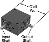
Transmit rotary motion at a right angle without changing speed or torque. Gear boxes are permanently lubricated to save maintenance time and effort. Connect to a motor using a shaft coupling (not included).
Max. Output | Max. Input | Input Shaft | Output Shaft | Overall | |||||||||
|---|---|---|---|---|---|---|---|---|---|---|---|---|---|
| Speed Ratio | Torque | Speed, rpm | Speed, rpm | hp | Dia., mm | Lg., mm | Dia., mm | Lg., mm | Lg., mm | Wd., mm | Ht., mm | Each | |
Gear Boxes | |||||||||||||
| 1:1 | 6 in.-lbs. @ 1,750 rpm | 3,000 | 3,000 | 0.19 | 5 | 16 | 5 | 16 | 56 | 56 | 25 | 0000000 | 0000000 |
| 1:1 | 18 in.-lbs. @ 1,750 rpm | 3,000 | 3,000 | 0.7 | 8 | 20 | 8 | 20 | 75 | 75 | 34 | 0000000 | 000000 |
| 1:1 | 40 in.-lbs. @ 1,750 rpm | 3,000 | 3,000 | 1.69 | 10 | 25 | 10 | 25 | 100 | 100 | 44 | 0000000 | 000000 |
| 1:1 | 124 in.-lbs. @ 1,750 rpm | 3,000 | 3,000 | 4.84 | 15 | 40 | 15 | 40 | 140 | 140 | 60 | 0000000 | 00000000 |
Gear Boxes with Two Flanges | |||||||||||||
| 1:1 | 19 in.-lbs. @ 1,750 rpm | 3,000 | 3,000 | 0.55 | 8 | 15 | 8 | 15 | 76 | 33 | 96 | 0000000 | 000000 |
| 1:1 | 70 in.-lbs. @ 1,750 rpm | 3,000 | 3,000 | 1.97 | 15 | 35 | 15 | 35 | 125 | 52 | 158 | 0000000 | 000000 |
Gear Boxes with Three Flanges | |||||||||||||
| 1:1 | 209 in.-lbs. @ 1,750 rpm | 3,000 | 3,000 | 5.82 | 20 | 50 | 20 | 50 | 200 | 76 | 239 | 0000000 | 000000 |
| 1:1 | 347 in.-lbs. @ 1,750 rpm | 3,000 | 3,000 | 9.66 | 25 | 70 | 25 | 70 | 230 | 100 | 281 | 0000000 | 000000 |
| 1:1 | 508 in.-lbs. @ 1,750 rpm | 3,000 | 3,000 | 14 | 35 | 70 | 35 | 70 | 230 | 100 | 281 | 0000000 | 000000 |
Compact Right-Angle Gear Boxes
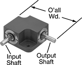
For small machinery and tight spots, these gear boxes transmit rotary motion at a right angle without changing speed or torque. All are permanently lubricated to save maintenance time and effort. Connect to a motor using a shaft coupling (not included).
Max. Output | Max. Input | Input Shaft | Output Shaft | Overall | |||||||||
|---|---|---|---|---|---|---|---|---|---|---|---|---|---|
| Speed Ratio | Torque | Speed, rpm | Speed, rpm | hp | Dia. | Lg. | Dia. | Lg. | Lg. | Wd. | Ht. | Each | |
| 1:1 | 0.44 in.-lbs. @ 1,750 rpm | 2,000 | 2,000 | 0.012 | 1/8" | 0.38" | 1/8" | 0.38" | 1 3/8" | 1 3/8" | 9/16" | 0000000 | 0000000 |
| 1:1 | 0.5 in.-lbs. @ 1,750 rpm | 3,000 | 3,000 | 0.014 | 3/16" | 0.5" | 3/16" | 0.5" | 1 7/8" | 1 7/8" | 3/4" | 0000000 | 000000 |
| 1:1 | 1.36 in.-lbs. @ 1,750 rpm | 3,000 | 3,000 | 0.038 | 1/4" | 0.75" | 1/4" | 0.75" | 2 1/2" | 2 1/2" | 1" | 0000000 | 000000 |
Metal Bevel Gears


A type of miter gear where one gear (sometimes called a pinion) is smaller than the other, bevel gears provide right-angle speed reduction at speed ratios ranging from 2:1 to 5:1. All are carbon steel for strength; they're compatible with plastic bevel gears. Teeth are not hardened so you can harden them to fit your application. Hardening a gear’s teeth increases its wear resistance.
A complete set consists of a gear and pinion (sold separately). For a gear and pinion to mesh correctly, they must have the same pressure angle, pitch/module, and face width. Shaft-mounted pinions come already securely fastened to a shaft.
Speed ratio is the ratio by which shaft speed is reduced when transferring motion from pinion to gear. To increase shaft speed, transfer motion from gear to pinion. Changing shaft speed also changes torque: as speed decreases, torque increases.
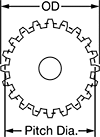

Hub | ||||||||||||||
|---|---|---|---|---|---|---|---|---|---|---|---|---|---|---|
| Face Wd. | Gear Pitch | Pressure Angle | Speed Ratio | Number of Teeth | Gear Pitch Dia. | OD | Overall Wd. | For Shaft Dia. | Mounting Distance (A) | Dia. | Wd. | Material | Each | |
Round Bore | ||||||||||||||
| 0.19" | 16 | 20° | 2:1 | 24 | 1 1/2" | 1.54" | 0.741" | 1/2" | 1" | 1" | 0.448" | 1144 Carbon Steel | 0000000 | 000000 |
| 0.35" | 16 | 20° | 2:1 | 32 | 2" | 2.03" | 0.871" | 1/2" | 1.188" | 1.125" | 0.5" | 1144 Carbon Steel | 0000000 | 00000 |
| 0.42" | 16 | 20° | 3:1 | 48 | 3" | 3.02" | 0.973" | 5/8" | 1.313" | 1.5" | 0.563" | 1144 Carbon Steel | 0000000 | 000000 |
| 0.48" | 16 | 20° | 4:1 | 64 | 4" | 4.02" | 1.019" | 5/8" | 1.375" | 2.25" | 0.563" | 1144 Carbon Steel | 0000000 | 000000 |
| 0.71" | 10 | 20° | 2:1 | 40 | 4" | 4.06" | 1.857" | 7/8" | 2.5" | 3" | 1.188" | 1144 Carbon Steel | 0000000 | 000000 |
| 0.78" | 10 | 20° | 3:1 | 60 | 6" | 6.04" | 2.04" | 1" | 2.75" | 3" | 1.375" | 1144 Carbon Steel | 0000000 | 000000 |


Hub | ||||||||||||||
|---|---|---|---|---|---|---|---|---|---|---|---|---|---|---|
| Face Wd., mm | Module | Pressure Angle | Speed Ratio | Number of Teeth | Gear Pitch Dia., mm | OD, mm | Overall Wd., mm | For Shaft Dia., mm | Mounting Distance (A), mm | Dia., mm | Wd., mm | Material | Each | |
Round Bore | ||||||||||||||
| 6 | 1 | 20° | 2:1 | 40 | 40 | 40.6 | 15 | 8 | 22 | 25 | 8 | Black-Oxide 1045 Carbon Steel | 00000000 | 000000 |
| 6 | 1 | 20° | 3:1 | 45 | 45 | 45.4 | 12 | 8 | 17 | 30 | 5 | Black-Oxide 1045 Carbon Steel | 00000000 | 00000 |
| 8 | 1.25 | 20° | 2:1 | 40 | 50 | 50.7 | 19 | 10 | 27 | 32 | 10 | Black-Oxide 1045 Carbon Steel | 00000000 | 00000 |
| 8 | 1.5 | 20° | 2:1 | 30 | 45 | 45.9 | 18 | 8 | 25 | 25 | 9 | Black-Oxide 1045 Carbon Steel | 00000000 | 00000 |
| 10 | 1.5 | 20° | 3:1 | 45 | 68 | 68.1 | 20 | 10 | 28 | 36 | 11 | Black-Oxide 1045 Carbon Steel | 00000000 | 00000 |
| 11 | 1.5 | 20° | 5:2 | 45 | 68 | 68.2 | 21 | 10 | 30 | 36 | 10 | Black-Oxide 1045 Carbon Steel | 00000000 | 00000 |
| 11 | 2 | 20° | 2:1 | 30 | 60 | 61.2 | 22 | 10 | 31 | 30 | 10 | Black-Oxide 1045 Carbon Steel | 00000000 | 00000 |
| 11 | 2 | 20° | 3:2 | 30 | 60 | 61.7 | 27 | 10 | 40 | 35 | 15 | Black-Oxide 1045 Carbon Steel | 00000000 | 00000 |
| 15 | 2 | 20° | 2:1 | 40 | 80 | 81.2 | 32 | 12 | 45 | 40 | 18 | Black-Oxide 1045 Carbon Steel | 00000000 | 00000 |
| 15 | 2.5 | 20° | 2:1 | 30 | 75 | 76.5 | 29 | 15 | 40 | 40 | 15 | Black-Oxide 1045 Carbon Steel | 00000000 | 00000 |
| 15 | 2.5 | 20° | 3:2 | 30 | 75 | 77.1 | 34 | 15 | 50 | 45 | 18 | Black-Oxide 1045 Carbon Steel | 00000000 | 00000 |
| 20 | 2.5 | 20° | 5:1 | 60 | 150 | 150.5 | 40 | 20 | 50 | 70 | 20 | Black-Oxide 1045 Carbon Steel | 00000000 | 000000 |


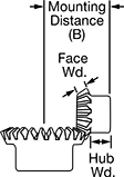
Hub | ||||||||||||||
|---|---|---|---|---|---|---|---|---|---|---|---|---|---|---|
| Face Wd. | Gear Pitch | Pressure Angle | Speed Ratio | Number of Teeth | Gear Pitch Dia. | OD | Overall Wd. | For Shaft Dia. | Mounting Distance (B) | Dia. | Wd. | Material | Each | |
Round Bore | ||||||||||||||
| 0.19" | 16 | 20° | 2:1 | 12 | 3/4" | 0.9" | 0.578" | 3/8" | 1.125" | 0.656" | 0.352" | 1144 Carbon Steel | 0000000 | 000000 |
| 0.35" | 16 | 20° | 2:1 | 16 | 1" | 1.15" | 0.837" | 3/8" | 1.5" | 0.813" | 0.453" | 1144 Carbon Steel | 0000000 | 00000 |
| 0.42" | 16 | 20° | 3:1 | 16 | 1" | 1.17" | 0.922" | 7/16" | 2" | 0.875" | 0.479" | 1144 Carbon Steel | 0000000 | 00000 |
| 0.48" | 16 | 20° | 4:1 | 16 | 1" | 1.17" | 0.984" | 1/2" | 2.5" | 0.813" | 0.476" | 1144 Carbon Steel | 0000000 | 00000 |
| 0.71" | 10 | 20° | 2:1 | 20 | 2" | 2.24" | 1.797" | 3/4" | 3.125" | 1.75" | 1.062" | 1144 Carbon Steel | 0000000 | 000000 |
| 0.79" | 10 | 20° | 3:1 | 20 | 2" | 2.27" | 2.156" | 7/8" | 4.375" | 1.75" | 1.333" | 1144 Carbon Steel | 0000000 | 000000 |


Hub | ||||||||||||||
|---|---|---|---|---|---|---|---|---|---|---|---|---|---|---|
| Face Wd., mm | Module | Pressure Angle | Speed Ratio | Number of Teeth | Gear Pitch Dia., mm | OD, mm | Overall Wd., mm | For Shaft Dia., mm | Mounting Distance (B), mm | Dia., mm | Wd., mm | Material | Each | |
Round Bore | ||||||||||||||
| 6 | 1 | 20° | 2:1 | 20 | 20 | 22.4 | 14 | 6 | 28 | 16 | 7 | Black-Oxide 1045 Carbon Steel | 00000000 | 000000 |
| 6 | 1 | 20° | 3:1 | 15 | 15 | 17.7 | 13 | 6 | 29 | 12 | 6 | Black-Oxide 1045 Carbon Steel | 00000000 | 00000 |
| 8 | 1.25 | 20° | 2:1 | 20 | 25 | 28 | 19 | 8 | 36 | 22 | 10 | Black-Oxide 1045 Carbon Steel | 00000000 | 00000 |
| 8 | 1.5 | 20° | 2:1 | 15 | 23 | 26.1 | 17 | 6 | 32 | 16 | 8 | Black-Oxide 1045 Carbon Steel | 00000000 | 00000 |
| 10 | 1.5 | 20° | 3:1 | 15 | 23 | 26.5 | 23 | 8 | 47 | 18 | 13 | Black-Oxide 1045 Carbon Steel | 00000000 | 00000 |
| 11 | 1.5 | 20° | 5:2 | 18 | 27 | 30.9 | 22 | 8 | 45 | 23 | 10 | Black-Oxide 1045 Carbon Steel | 00000000 | 00000 |
| 11 | 2 | 20° | 2:1 | 15 | 30 | 34.8 | 21 | 8 | 40 | 22 | 8 | Black-Oxide 1045 Carbon Steel | 00000000 | 00000 |
| 11 | 2 | 20° | 3:2 | 20 | 40 | 44.2 | 25 | 10 | 45 | 30 | 12 | Black-Oxide 1045 Carbon Steel | 00000000 | 00000 |
| 15 | 2 | 20° | 2:1 | 20 | 40 | 44.8 | 34 | 12 | 60 | 32 | 18 | Black-Oxide 1045 Carbon Steel | 00000000 | 00000 |
| 15 | 2.5 | 20° | 2:1 | 15 | 38 | 43.5 | 32 | 12 | 55 | 30 | 16 | Black-Oxide 1045 Carbon Steel | 00000000 | 00000 |
| 15 | 2.5 | 20° | 3:2 | 20 | 50 | 55.2 | 31 | 12 | 55 | 35 | 13 | Black-Oxide 1045 Carbon Steel | 00000000 | 00000 |


Shaft | Hub | ||||||||||||||
|---|---|---|---|---|---|---|---|---|---|---|---|---|---|---|---|
| Face Wd., mm | Module | Pressure Angle | Speed Ratio | Number of Teeth | Gear Pitch Dia., mm | OD, mm | Overall Wd., mm | Dia., mm | Lg., mm | Mounting Distance (B), mm | Dia., mm | Wd., mm | Material | Each | |
| 20 | 2.5 | 20° | 5:1 | 12 | 30 | 37.1 | 143 | 20.2 | 115 | 83 | 25 | 8 | Black-Oxide 1045 Carbon Steel | 00000000 | 000000 |
High-Power Metal Bevel Gears
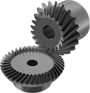
Made from carbon steel with spiral teeth, these gears handle heavier loads at higher speeds than bevel gears with straight teeth because their teeth stay in contact longer. Their teeth engage gradually, which reduces vibration and noise, and they’re hardened for extra wear resistance. Use these gears to transmit motion at a right angle while changing shaft speed and torque. They reduce speeds at ratios of 2:1, 3:1, or 4:1. Customize their machinable bore to fit them on a variety of shafts. They’re also known as spiral bevel gears.
A complete set consists of a gear and pinion (sold separately). The gear is larger than the pinion, but for them to mesh correctly, they must have the same pressure angle, module, and face width.
Speed ratio is the ratio by which shaft speed is reduced when transferring motion from pinion to gear. To increase shaft speed, transfer motion from gear to pinion. Changing shaft speed also changes torque: as speed decreases, torque increases.

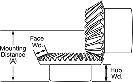
Hub | |||||||||||||
|---|---|---|---|---|---|---|---|---|---|---|---|---|---|
| Face Width, mm | Pressure Angle | Speed Ratio | Number of Teeth | Gear Pitch Dia., mm | OD, mm | Overall Width, mm | For Shaft Diameter, mm | Mounting Distance (A), mm | Material | Diameter, mm | Width, mm | Each | |
Machinable Round Bore | |||||||||||||
| 6 | 20° | 2:1 | 40 | 40 | 40.52 | 15 | 8-18 | 22 | Black-Oxide 1045 Carbon Steel | 25 | 8 | 0000000 | 000000 |
| 10 | 20° | 2:1 | 40 | 60 | 60.75 | 24.9 | 10-25 | 35 | Black-Oxide 1045 Carbon Steel | 38 | 15 | 0000000 | 00000 |
| 12 | 20° | 4:1 | 60 | 90 | 90.36 | 24.1 | 12-45 | 32 | Black-Oxide 1045 Carbon Steel | 60 | 12 | 0000000 | 000000 |
| 15 | 20° | 3:1 | 45 | 90 | 90.67 | 30.3 | 12-30 | 40 | Black-Oxide 1045 Carbon Steel | 40 | 17 | 0000000 | 000000 |


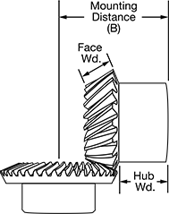
Hub | |||||||||||||
|---|---|---|---|---|---|---|---|---|---|---|---|---|---|
| Face Width, mm | Pressure Angle | Speed Ratio | Number of Teeth | Gear Pitch Dia., mm | OD, mm | Overall Width, mm | For Shaft Diameter, mm | Mounting Distance (B), mm | Material | Diameter, mm | Width, mm | Each | |
Machinable Round Bore | |||||||||||||
| 6 | 20° | 2:1 | 20 | 20 | 22.08 | 13.7 | 6-9 | 28 | Black-Oxide 1045 Carbon Steel | 16 | 7 | 0000000 | 000000 |
| 10 | 20° | 2:1 | 20 | 30 | 33.08 | 25.5 | 8-15 | 46 | Black-Oxide 1045 Carbon Steel | 25 | 15 | 0000000 | 00000 |
| 12 | 20° | 4:1 | 15 | 23 | 26.09 | 23 | 8-10 | 56 | Black-Oxide 1045 Carbon Steel | 18 | 10 | 0000000 | 00000 |
| 15 | 20° | 3:1 | 15 | 30 | 34.78 | 29.7 | 10-14 | 60 | Black-Oxide 1045 Carbon Steel | 24 | 14 | 0000000 | 00000 |
Plastic Bevel Gears
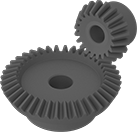
Reduce speeds where noise, corrosion, and frequent lubrication are a concern. Compared to metal gears, these nylon gears run more quietly, won't rust, and don't need to be lubricated. Because they’re self-lubricating, these bevel gears are commonly used in food machinery. They should not, however, come in direct contact with food or chemicals that will come in contact with food.
A complete set consists of a gear and pinion (sold separately). For a gear and pinion to mesh correctly, they must have the same pressure angle, module, and face width. Plastic pinions can also be mated with metal gears, and plastic gears with metal pinions.
Speed ratio is the ratio by which shaft speed is reduced when transferring motion from pinion to gear. To increase shaft speed, transfer motion from gear to pinion. Changing shaft speed also changes torque: as speed decreases, torque increases.
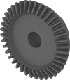


Hub | ||||||||||||||||
|---|---|---|---|---|---|---|---|---|---|---|---|---|---|---|---|---|
| Face Width, mm | Module | Pressure Angle | Speed Ratio | Number of Teeth | Gear Pitch Dia., mm | OD, mm | Overall Width, mm | For Shaft Diameter, mm | Mounting Distance (A), mm | Material | Fabrication | Color | Diameter, mm | Width, mm | Each | |
Round Bore | ||||||||||||||||
| 6 | 1 | 20° | 2:1 | 40 | 40 | 40.6 | 15 | 8 | 22 | Nylon Plastic | Molded | Blue | 25 | 8 | 00000000 | 000000 |
| 8 | 1.25 | 20° | 2:1 | 40 | 50 | 50.7 | 19 | 10 | 27 | Nylon Plastic | Molded | Blue | 32 | 10 | 00000000 | 00000 |

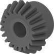


Hub | ||||||||||||||||
|---|---|---|---|---|---|---|---|---|---|---|---|---|---|---|---|---|
| Face Width, mm | Module | Pressure Angle | Speed Ratio | Number of Teeth | Gear Pitch Dia., mm | OD, mm | Overall Width, mm | For Shaft Diameter, mm | Mounting Distance (B), mm | Material | Fabrication | Color | Diameter, mm | Width, mm | Each | |
Round Bore | ||||||||||||||||
| 6 | 1 | 20° | 2:1 | 20 | 20 | 22.4 | 14 | 6 | 28 | Nylon Plastic | Molded | Blue | 16 | 7 | 00000000 | 000000 |
| 8 | 1.25 | 20° | 2:1 | 20 | 25 | 28 | 19 | 8 | 36 | Nylon Plastic | Molded | Blue | 22 | 10 | 00000000 | 00000 |


