


Filter by
Mount Type


Height

For Suspending
DFARS Specialty Metals
Export Control Classification Number (ECCN)
Easy-Position Beam Clamps for Pipe, Tube, and Conduit
 |
Press Fit |
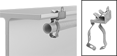
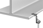
Suspend material at any angle from the beam. Clamps have a fixed jaw that secures to the beam and a hanger that swivels 360° to position material and accommodate for misalignment.
Press Fit—Install press-fit clamps by lightly hammering them onto the beam.
For OD | For Beam Thk. | ||||||||||||||||
|---|---|---|---|---|---|---|---|---|---|---|---|---|---|---|---|---|---|
Mount Type | For Beam Shape | Inch | Metric, mm | For Pipe Size | Min. | Max. | Wt. Cap., lb. | Range of Motion | Throat Dp. | Surface to Pipe Center | Lg. | Wd. | Ht. | Each | |||
Bottom and Top Beam Mount | |||||||||||||||||
Zinc-Plated Steel | |||||||||||||||||
| Press Fit | Flat, Taper | 3/4" to 1" | 19 to 25 | 1/2 | 1/8" | 1/4" | 75 | 360° | 1" | 3/4" | 1 3/8" | 1 3/4" | 3" | 3007T211 | 00000 | ||
| Press Fit | Flat, Taper | 3/4" to 1" | 19 to 25 | 1/2 | 5/16" | 1/2" | 75 | 360° | 1" | 3/4" | 1 3/8" | 1 3/4" | 3 1/4" | 3007T11 | 0000 | ||
| Press Fit | Flat, Taper | 3/4" to 1" | 19 to 25 | 1/2 | 9/16" | 3/4" | 75 | 360° | 1" | 3/4" | 1 1/2" | 1 3/4" | 3 1/2" | 3007T212 | 0000 | ||
| Press Fit | Flat, Taper | 3/4" to 1" | 19 to 25 | 1/2 | 13/16" | 1 1/8" | 75 | 360° | 1" | 3/4" | 1 1/2" | 1 3/4" | 3 3/4" | 3007T213 | 0000 | ||
| Press Fit | Flat, Taper | 1 3/16" to 1 5/16" | 30 to 33 | 1 | 1/8" | 1/4" | 75 | 360° | 1" | 1" | 1 3/8" | 1 3/4" | 3 1/2" | 3007T214 | 0000 | ||
| Press Fit | Flat, Taper | 1 3/16" to 1 5/16" | 30 to 33 | 1 | 5/16" | 1/2" | 75 | 360° | 1" | 1" | 1 3/8" | 1 3/4" | 3 3/4" | 3007T12 | 0000 | ||
| Press Fit | Flat, Taper | 1 3/16" to 1 5/16" | 30 to 33 | 1 | 9/16" | 3/4" | 75 | 360° | 1" | 1" | 1 1/2" | 1 3/4" | 4" | 3007T215 | 0000 | ||
| Press Fit | Flat, Taper | 1 5/16" to 1 5/8" | 33 to 41 | 1 1/4 | 1/8" | 1/4" | 75 | 360° | 1" | 1" | 1 3/8" | 1 3/4" | 3 3/4" | 3007T216 | 0000 | ||
| Press Fit | Flat, Taper | 1 5/16" to 1 5/8" | 33 to 41 | 1 1/4 | 5/16" | 1/2" | 75 | 360° | 1" | 1" | 1 3/8" | 1 3/4" | 4" | 3007T13 | 0000 | ||
| Press Fit | Flat, Taper | 1 3/4" to 1 7/8" | 44 to 48 | 1 1/2 | 5/16" | 1/2" | 75 | 360° | 1" | 1 1/4" | 1 3/8" | 1 3/4" | 4 1/4" | 3007T14 | 0000 | ||
| Press Fit | Flat, Taper | 1 7/8" to 2 3/8" | 48 to 60 | 2 | 5/16" | 1/2" | 75 | 360° | 1" | 1 1/2" | 1 3/8" | 1 3/4" | 5" | 3007T15 | 0000 | ||
| Press Fit | Flat, Taper | 1 7/8" to 2 3/8" | 48 to 60 | 2 | 9/16" | 3/4" | 75 | 360° | 1" | 1 1/2" | 1 1/2" | 1 3/4" | 5 1/4" | 3007T221 | 0000 | ||
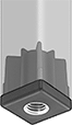
Press-Fit Leveling Mount Inserts
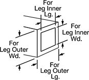
For Square Legs
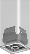 |  |
Square inserts have flexible spring steel walls that grip the inside of the legs.
For Leg | Thread | ||||||||||||
|---|---|---|---|---|---|---|---|---|---|---|---|---|---|
Outer Lg. | Outer Wd. | Inner Lg. | Inner Wd. | Cap. per Mount | Overall Ht. | Size | Type | Dp. | Pkg. Qty. | Pkg. | |||
Zinc-Plated Steel | |||||||||||||
| 1" | 1" | 15/16" | 15/16" | Not Rated | 1 1/16" | 1/4"-20 | UNC | 1/4" | 4 | 2417T27 | 00000 | ||
| 1" | 1" | 15/16" | 15/16" | Not Rated | 1 1/16" | 5/16"-18 | UNC | 1/4" | 4 | 2417T28 | 0000 | ||
| 1" | 1" | 15/16" | 15/16" | Not Rated | 1 1/16" | 3/8"-16 | UNC | 1/4" | 4 | 2417T11 | 00000 | ||
| 1 1/4" | 1 1/4" | 1 3/16" | 1 3/16" | Not Rated | 1 1/16" | 1/4"-20 | UNC | 1/4" | 4 | 2417T61 | 00000 | ||
| 1 1/4" | 1 1/4" | 1 3/16" | 1 3/16" | Not Rated | 1 1/16" | 5/16"-18 | UNC | 1/4" | 4 | 2417T62 | 00000 | ||
| 1 1/4" | 1 1/4" | 1 3/16" | 1 3/16" | Not Rated | 1 1/16" | 3/8"-16 | UNC | 1/4" | 4 | 2417T12 | 00000 | ||
| 1 1/2" | 1 1/2" | 1 7/16" | 1 7/16" | Not Rated | 1 1/16" | 3/8"-16 | UNC | 1/4" | 4 | 2417T63 | 00000 | ||
| 1 1/2" | 1 1/2" | 1 7/16" | 1 7/16" | Not Rated | 2 1/8" | 1/2"-13 | UNC | 1/2" | 1 | 2417T13 | 00000 | ||
| 1 3/4" | 1 3/4" | 1 11/16" | 1 11/16" | Not Rated | 2 1/16" | 1/2"-13 | UNC | 1/2" | 1 | 2417T14 | 00000 | ||
| 2" | 2" | 1 15/16" | 1 15/16" | Not Rated | 2 1/16" | 1/2"-13 | UNC | 1/2" | 1 | 2417T15 | 00000 | ||
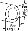
For Round Legs
 |
 |
For Leg | Thread | ||||||||||
|---|---|---|---|---|---|---|---|---|---|---|---|
ID | OD | Cap. per Mount | Overall Ht. | Size | Type | Dp. | Pkg. Qty. | Pkg. | |||
Zinc-Plated Steel | |||||||||||
| 11/16" | 3/4" | Not Rated | 5/8" | 1/4"-20 | UNC | 3/8" | 4 | 2417T26 | 000000 | ||
| 11/16" | 3/4" | Not Rated | 5/8" | 5/16"-18 | UNC | 3/8" | 4 | 2417T29 | 00000 | ||
| 15/16" | 1" | Not Rated | 9/16" | 3/8"-16 | UNC | 3/8" | 4 | 2417T18 | 00000 | ||
| 15/16" | 1" | Not Rated | 5/8" | 1/4"-20 | UNC | 3/8" | 4 | 2417T16 | 00000 | ||
| 15/16" | 1" | Not Rated | 5/8" | 5/16"-18 | UNC | 3/8" | 4 | 2417T17 | 00000 | ||
| 1 3/16" | 1 1/4" | Not Rated | 5/8" | 1/4"-20 | UNC | 3/8" | 4 | 2417T19 | 00000 | ||
| 1 3/16" | 1 1/4" | Not Rated | 5/8" | 5/16"-18 | UNC | 3/8" | 4 | 2417T21 | 00000 | ||
| 1 3/16" | 1 1/4" | Not Rated | 5/8" | 3/8"-16 | UNC | 3/8" | 4 | 2417T22 | 00000 | ||
| 1 7/16" | 1 1/2" | Not Rated | 5/8" | 1/4"-20 | UNC | 3/8" | 4 | 2417T23 | 00000 | ||
| 1 7/16" | 1 1/2" | Not Rated | 5/8" | 5/16"-18 | UNC | 3/8" | 4 | 2417T24 | 00000 | ||
| 1 7/16" | 1 1/2" | Not Rated | 5/8" | 3/8"-16 | UNC | 3/8" | 4 | 2417T25 | 00000 | ||
| 1 15/16" | 2" | Not Rated | 3/8" | 3/8"-16 | UNC | 3/8" | 4 | 2417T32 | 00000 | ||
| 1 15/16" | 2" | Not Rated | 5/8" | 1/4"-20 | UNC | 3/8" | 4 | 2417T31 | 00000 | ||
| 2 7/16" | 2 1/2" | Not Rated | 5/8" | 3/8"-16 | UNC | 3/8" | 4 | 2417T33 | 00000 | ||
Press-Fit Beam Clamps for Threaded Rods
 |
A toothed clip secures these clamps to the beam—no fasteners required. Lightly tap with a hammer to install.
For Beam Thk. | |||||||||||||
|---|---|---|---|---|---|---|---|---|---|---|---|---|---|
For Beam Shape | For Thread Size | Min. | Max. | Wt. Cap., lb. | Mount Type | Lg. | Wd. | Ht. | Threaded Rod Included | Each | |||
Bottom and Top Beam Mount | |||||||||||||
Steel | |||||||||||||
| Flat, Taper | 1/4"-20 | 1/8" | 1/4" | 150 | Press Fit | 7/8" | 1 3/8" | 1 7/8" | No | 11715T81 | 00000 | ||
| Flat, Taper | 1/4"-20 | 5/16" | 1/2" | 150 | Press Fit | 7/8" | 1 3/8" | 2 1/4" | No | 11715T82 | 0000 | ||
| Flat, Taper | 1/4"-20 | 9/16" | 3/4" | 150 | Press Fit | 7/8" | 1 3/8" | 2 3/8" | No | 11715T83 | 0000 | ||
| Flat, Taper | 3/8"-16 | 1/8" | 1/4" | 150 | Press Fit | 7/8" | 1 3/8" | 1 7/8" | No | 11715T84 | 0000 | ||
| Flat, Taper | 3/8"-16 | 5/16" | 1/2" | 150 | Press Fit | 7/8" | 1 3/8" | 2 1/4" | No | 11715T85 | 0000 | ||
| Flat, Taper | 3/8"-16 | 9/16" | 3/4" | 150 | Press Fit | 7/8" | 1 3/8" | 2 3/8" | No | 11715T86 | 0000 | ||
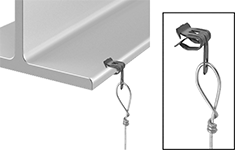
Beam Clamps with Tie Wire Hangers
High-Capacity Press-Fit Leveling Mount Inserts
For Square Legs
 |
Shown with Brass Insert Installed |
Plastic—The economical choice. These inserts can handle more weight than inserts with brass threads, but may wear out more quickly if frequently adjusted.
Plastic with Brass Insert—Move equipment around your workspace and make frequent adjustments without worrying about stripping the brass threads.
For Leg | Thread | |||||||||||||
|---|---|---|---|---|---|---|---|---|---|---|---|---|---|---|
Outer Lg. | Outer Wd. | Inner Lg. | Inner Wd. | Cap. per Mount, lb. | Overall Ht. | , mm | Size | Type | Dp. | Temp., ° F | Each | |||
Plastic | ||||||||||||||
| ||||||||||||||
| 1 1/2" | 1 1/2" | 1 1/4" | 1 1/4" | 3,500 | 1 3/4" | — | 3/8"-16 | UNC | 1 1/4" | -20 to 170 | 6675N32 | 00000 | ||
| 1 1/2" | 1 1/2" | 1 1/4" | 1 1/4" | 3,500 | 1 3/4" | — | 1/2"-13 | UNC | 1 1/4" | -20 to 170 | 6675N42 | 0000 | ||
| 1 1/2" | 1 1/2" | 1 1/4" | 1 1/4" | 3,500 | 1 3/4" | — | 5/8"-11 | UNC | 1 1/4" | -20 to 170 | 6675N52 | 0000 | ||
| 1 1/2" | 1 1/2" | 1 1/4" | 1 1/4" | 3,500 | 1 3/4" | — | 3/4"-10 | UNC | 1 1/4" | -20 to 170 | 6675N62 | 0000 | ||
| 1 1/2" | 1 1/2" | 1 3/8" | 1 3/8" | 3,500 | 1 3/4" | — | 3/8"-16 | UNC | 1 1/4" | -20 to 170 | 6675N31 | 0000 | ||
| 1 1/2" | 1 1/2" | 1 3/8" | 1 3/8" | 3,500 | 1 3/4" | — | 1/2"-13 | UNC | 1 1/4" | -20 to 170 | 6675N41 | 0000 | ||
| 1 1/2" | 1 1/2" | 1 3/8" | 1 3/8" | 3,500 | 1 3/4" | — | 5/8"-11 | UNC | 1 1/4" | -20 to 170 | 6675N51 | 0000 | ||
| 1 1/2" | 1 1/2" | 1 3/8" | 1 3/8" | 3,500 | 1 3/4" | — | 3/4"-10 | UNC | 1 1/4" | -20 to 170 | 6675N61 | 0000 | ||
| 2" | 2" | 1 3/4" | 1 3/4" | 3,500 | 2" | — | 3/8"-16 | UNC | 1" | -20 to 170 | 6675N35 | 0000 | ||
| 2" | 2" | 1 3/4" | 1 3/4" | 3,500 | 2" | — | 1/2"-13 | UNC | 1" | -20 to 170 | 6675N45 | 0000 | ||
| 2" | 2" | 1 3/4" | 1 3/4" | 3,500 | 2" | — | 5/8"-11 | UNC | 1" | -20 to 170 | 6675N55 | 0000 | ||
| 2" | 2" | 1 3/4" | 1 3/4" | 3,500 | 2" | — | 3/4"-10 | UNC | 1" | -20 to 170 | 6675N65 | 0000 | ||
| 2" | 2" | 1 7/8" | 1 7/8" | 3,500 | 2" | — | 3/8"-16 | UNC | 1" | -20 to 170 | 6675N34 | 0000 | ||
| 2" | 2" | 1 7/8" | 1 7/8" | 3,500 | 2" | — | 1/2"-13 | UNC | 1" | -20 to 170 | 6675N44 | 0000 | ||
| 2" | 2" | 1 7/8" | 1 7/8" | 3,500 | 2" | — | 5/8"-11 | UNC | 1" | -20 to 170 | 6675N54 | 0000 | ||
| 2" | 2" | 1 7/8" | 1 7/8" | 3,500 | 2" | — | 3/4"-10 | UNC | 1" | -20 to 170 | 6675N64 | 0000 | ||
Plastic with Brass Insert | ||||||||||||||
| ||||||||||||||
| 1" | 1" | 7/8" | 7/8" | 1,100 | 1 3/16" | — | 3/8"-16 | UNC | 7/8" | 30 to 195 | 60945K56 | 0000 | ||
| 1" | 1" | 7/8" | 7/8" | 1,100 | 1 3/16" | — | 1/2"-13 | UNC | 7/8" | 30 to 195 | 60945K57 | 0000 | ||
| 1 3/16" | 1 3/16" | 1 1/16" | 1 1/16" | 1,200 | 1 5/16" | — | 3/8"-16 | UNC | 7/8" | 30 to 195 | 60945K58 | 00000 | ||
| 1 1/2" | 1 1/2" | 1 1/4" | 1 1/4" | 1,000 | 1 11/16" | — | 3/8"-16 | UNC | 3/4" | 30 to 195 | 60945K25 | 00000 | ||
| 1 1/2" | 1 1/2" | 1 1/4" | 1 1/4" | 1,000 | 1 11/16" | — | 1/2"-13 | UNC | 3/4" | 30 to 195 | 60945K26 | 00000 | ||
| 1 1/2" | 1 1/2" | 1 1/4" | 1 1/4" | 1,000 | 1 11/16" | — | 5/8"-11 | UNC | 15/16" | 30 to 195 | 60945K27 | 00000 | ||
| 1 1/2" | 1 1/2" | 1 1/4" | 1 1/4" | 1,000 | 1 11/16" | — | 3/4"-10 | UNC | 1 1/8" | 30 to 195 | 60945K28 | 00000 | ||
| 1 1/2" | 1 1/2" | 1 1/4" | 1 1/4" | 1,500 | 1 3/4" | — | 3/8"-12 | Acme | 1 1/4" | -20 to 180 | 60945K36 | 0000 | ||
| 1 1/2" | 1 1/2" | 1 1/4" | 1 1/4" | 1,500 | 1 3/4" | — | 1/2"-10 | Acme | 1 1/4" | -20 to 180 | 60945K37 | 0000 | ||
| 1 1/2" | 1 1/2" | 1 5/16" | 1 5/16" | 1,500 | 1 11/16" | 1.5 | M10 | Metric | 1" | -20 to 180 | 60945K75 | 0000 | ||
| 1 1/2" | 1 1/2" | 1 5/16" | 1 5/16" | 1,500 | 1 11/16" | 1.75 | M12 | Metric | 1" | -20 to 180 | 60945K76 | 0000 | ||
| 1 1/2" | 1 1/2" | 1 5/16" | 1 5/16" | 1,500 | 1 11/16" | 2 | M16 | Metric | 1" | -20 to 180 | 60945K77 | 0000 | ||
| 1 1/2" | 1 1/2" | 1 5/16" | 1 5/16" | 1,500 | 1 11/16" | 2.5 | M20 | Metric | 1" | -20 to 180 | 60945K78 | 0000 | ||
| 1 1/2" | 1 1/2" | 1 3/8" | 1 3/8" | 1,000 | 1 11/16" | — | 3/8"-16 | UNC | 3/4" | 30 to 195 | 60945K21 | 00000 | ||
| 1 1/2" | 1 1/2" | 1 3/8" | 1 3/8" | 1,000 | 1 11/16" | — | 1/2"-13 | UNC | 3/4" | 30 to 195 | 60945K22 | 00000 | ||
| 1 1/2" | 1 1/2" | 1 3/8" | 1 3/8" | 1,000 | 1 11/16" | — | 5/8"-11 | UNC | 15/16" | 30 to 195 | 60945K23 | 00000 | ||
| 1 1/2" | 1 1/2" | 1 3/8" | 1 3/8" | 1,000 | 1 11/16" | — | 3/4"-10 | UNC | 1 1/8" | 30 to 195 | 60945K24 | 00000 | ||
| 2" | 2" | 1 3/4" | 1 3/4" | 1,000 | 1 15/16" | — | 3/8"-16 | UNC | 3/4" | 30 to 195 | 60945K29 | 00000 | ||
| 2" | 2" | 1 3/4" | 1 3/4" | 1,000 | 1 15/16" | — | 1/2"-13 | UNC | 3/4" | 30 to 195 | 60945K31 | 00000 | ||
| 2" | 2" | 1 3/4" | 1 3/4" | 1,000 | 1 15/16" | — | 5/8"-11 | UNC | 15/16" | 30 to 195 | 60945K32 | 00000 | ||
| 2" | 2" | 1 3/4" | 1 3/4" | 1,760 | 1 15/16" | — | 3/4"-10 | UNC | 1 1/8" | 30 to 195 | 60945K33 | 00000 | ||
| 2" | 2" | 1 3/4" | 1 3/4" | 2,000 | 2" | — | 3/8"-12 | Acme | 1" | -20 to 180 | 60945K38 | 0000 | ||
| 2" | 2" | 1 3/4" | 1 3/4" | 2,000 | 2" | — | 1/2"-10 | Acme | 1" | -20 to 180 | 60945K39 | 0000 | ||
| 2" | 2" | 1 3/4" | 1 3/4" | 2,000 | 2" | 1.5 | M10 | Metric | 1" | -20 to 180 | 60945K79 | 0000 | ||
| 2" | 2" | 1 3/4" | 1 3/4" | 2,000 | 2" | 1.75 | M12 | Metric | 1" | -20 to 180 | 60945K81 | 0000 | ||
| 2" | 2" | 1 3/4" | 1 3/4" | 2,000 | 2" | 2 | M16 | Metric | 1" | -20 to 180 | 60945K82 | 0000 | ||
| 2" | 2" | 1 3/4" | 1 3/4" | 2,000 | 2" | 2.5 | M20 | Metric | 1" | -20 to 180 | 60945K83 | 0000 | ||
| 2" | 2" | 1 7/8" | 1 7/8" | 1,000 | 1 15/16" | — | 3/8"-16 | UNC | 3/4" | 30 to 195 | 60945K52 | 00000 | ||
| 2" | 2" | 1 7/8" | 1 7/8" | 1,000 | 1 15/16" | — | 1/2"-13 | UNC | 3/4" | 30 to 195 | 60945K53 | 00000 | ||
| 2" | 2" | 1 7/8" | 1 7/8" | 1,000 | 1 15/16" | — | 5/8"-11 | UNC | 15/16" | 30 to 195 | 60945K54 | 00000 | ||
| 2" | 2" | 1 7/8" | 1 7/8" | 1,760 | 1 15/16" | — | 3/4"-10 | UNC | 1 1/8" | 30 to 195 | 60945K55 | 00000 | ||
For Rectangular Legs

For Round Legs
| |
Shown with Brass Insert Installed |
Plastic with Brass Insert—Move equipment around your workspace and make frequent adjustments without worrying about stripping the brass threads.
For Leg | Thread | |||||||||||
|---|---|---|---|---|---|---|---|---|---|---|---|---|
ID | OD | Cap. per Mount, lb. | Overall Ht. | , mm | Size | Type | Dp. | Temp., ° F | Each | |||
Plastic with Brass Insert | ||||||||||||
| 1 5/16" | 1 1/2" | 1,500 | 1 11/16" | 1.5 | M10 | Metric | 1" | -20 to 180 | 60945K91 | 00000 | ||
| 1 5/16" | 1 1/2" | 1,500 | 1 11/16" | 1.75 | M12 | Metric | 1" | -20 to 180 | 60945K92 | 0000 | ||
| 1 5/16" | 1 1/2" | 1,500 | 1 11/16" | 2 | M16 | Metric | 1" | -20 to 180 | 60945K93 | 0000 | ||
| 1 3/8" | 1 1/2" | 1,000 | 1 11/16" | — | 3/8"-16 | UNC | 3/4" | 30 to 195 | 60945K13 | 00000 | ||
| 1 3/8" | 1 1/2" | 1,000 | 1 11/16" | — | 1/2"-13 | UNC | 3/4" | 30 to 195 | 60945K14 | 00000 | ||
| 1 3/8" | 1 1/2" | 1,000 | 1 11/16" | — | 5/8"-11 | UNC | 15/16" | 30 to 195 | 60945K15 | 00000 | ||
| 1 3/8" | 1 1/2" | 1,000 | 1 11/16" | — | 3/4"-10 | UNC | 1 1/8" | 30 to 195 | 60945K42 | 00000 | ||
| 1 9/16" | 1 11/16" | 1,000 | 1 11/16" | — | 3/8"-16 | UNC | 7/8" | 30 to 195 | 60945K84 | 00000 | ||
| 1 9/16" | 1 11/16" | 1,000 | 1 11/16" | — | 1/2"-13 | UNC | 7/8" | 30 to 195 | 60945K85 | 00000 | ||
| 1 9/16" | 1 11/16" | 1,000 | 1 11/16" | — | 5/8"-11 | UNC | 7/8" | 30 to 195 | 60945K86 | 00000 | ||
| 1 11/16" | 1 15/16" | 1,000 | 1 15/16" | — | 3/8"-16 | UNC | 3/4" | 30 to 195 | 60945K65 | 00000 | ||
| 1 11/16" | 1 15/16" | 1,000 | 1 15/16" | — | 1/2"-13 | UNC | 3/4" | 30 to 195 | 60945K66 | 00000 | ||
| 1 11/16" | 1 15/16" | 1,000 | 1 15/16" | — | 5/8"-11 | UNC | 15/16" | 30 to 195 | 60945K67 | 00000 | ||
| 1 11/16" | 1 15/16" | 1,760 | 1 15/16" | — | 3/4"-10 | UNC | 1 1/8" | 30 to 195 | 60945K68 | 00000 | ||
| 1 11/16" | 2" | 2,000 | 1 15/16" | — | 3/8"-16 | UNC | 1" | 30 to 195 | 60945K411 | 0000 | ||
| 1 11/16" | 2" | 2,000 | 1 15/16" | — | 1/2"-13 | UNC | 1" | 30 to 195 | 60945K412 | 0000 | ||
| 1 13/16" | 2" | 2,000 | 1 15/16" | 1.5 | M10 | Metric | 1" | -20 to 180 | 60945K95 | 0000 | ||
| 1 13/16" | 2" | 2,000 | 1 15/16" | 1.75 | M12 | Metric | 1" | -20 to 180 | 60945K96 | 0000 | ||
| 1 13/16" | 2" | 2,000 | 1 15/16" | 2 | M16 | Metric | 1" | -20 to 180 | 60945K97 | 0000 | ||
| 1 13/16" | 2" | 2,000 | 1 15/16" | 2.5 | M20 | Metric | 1" | -20 to 180 | 60945K98 | 0000 | ||
| 1 7/8" | 2" | 2,000 | 1 15/16" | — | 3/8"-16 | UNC | 1" | 30 to 195 | 60945K413 | 0000 | ||
| 1 7/8" | 2" | 2,000 | 1 15/16" | — | 1/2"-13 | UNC | 1" | 30 to 195 | 60945K414 | 0000 | ||
| 1 7/8" | 2" | 2,000 | 1 15/16" | — | 5/8"-11 | UNC | 1" | 30 to 195 | 60945K415 | 0000 | ||
| 1 15/16" | 2" | 1,000 | 1 15/16" | — | 3/8"-16 | UNC | 3/4" | 30 to 195 | 60945K16 | 00000 | ||
| 1 15/16" | 2" | 1,000 | 1 15/16" | — | 1/2"-13 | UNC | 3/4" | 30 to 195 | 60945K17 | 00000 | ||
| 1 15/16" | 2" | 1,000 | 1 15/16" | — | 5/8"-11 | UNC | 15/16" | 30 to 195 | 60945K46 | 00000 | ||
| 1 15/16" | 2" | 1,760 | 1 15/16" | — | 3/4"-10 | UNC | 1 1/8" | 30 to 195 | 60945K48 | 00000 | ||
| 2 1/4" | 2 3/8" | 1,700 | 1 15/16" | — | 5/8"-11 | UNC | 1 1/2" | 30 to 195 | 60945K88 | 00000 | ||
Routing Rings
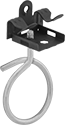 |
Press Fit |
Also known as bridle rings, routing rings have an open-eye design that allows you to quickly install wire and cable.
Press Fit—Press fit routing rings mount onto beams and other flat surfaces. A hole on the back of the jaw allows you to orient the ring horizontally. Lightly hammer to install.
