


Filter by
Mounting Location
Adjustment Movement
System of Measurement
Overall Height
Base Mount Type


Load Capacity
Base Width
For Monitor Size
Finish
Projection
Export Control Classification Number (ECCN)
DFARS Specialty Metals
Component
Display Height
Tool Support Arms
 |
Bench Top |
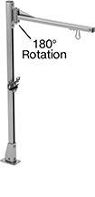
Suspend tools to keep them out of the way but still within reach. Attaching brackets slide along the length of the arm.
Base | |||||||||||||||
|---|---|---|---|---|---|---|---|---|---|---|---|---|---|---|---|
Max. Range of Motion | Max. Projection | Overall Ht. | Max. Load Cap., lb. | Material | Lg. | Wd. | Mount Type | No. of Mounting Holes | Mounting Hole Dia. | Mounting Fasteners Included | Attaching End Mount Type | Each | |||
In and Out, Rotate, Side to Side | |||||||||||||||
Bench Top | |||||||||||||||
| 180° | 24" | 48" | 30 | Steel | 5 1/2" | 3 1/2" | Screw On | 4 | 0.422" | Yes | Eyebolt | 6139T241 | 0000000 | ||
Benchtop Monitor Mounts
Adjustable Height
 |
Screw On |
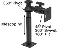
Adjust your monitor to eye level for comfortable viewing. Tilt the mounting plate to reduce glare.
Swivel Plate—Quickly rotate your monitor between portrait and landscape mode.
Base | ||||||||||||||
|---|---|---|---|---|---|---|---|---|---|---|---|---|---|---|
For Monitor Size | Max. Load Cap., lb. | Display Ht. | Max. Projection | Material | Lg. | Wd. | Monitor Mounting Pattern Compatibility | Mounting Fasteners Included | Adjustment Movement | Features | Each | |||
Screw-On Base | ||||||||||||||
| 10" to 32" | 10 | 8" to 21 1/4" | 7 1/4" | Black Powder-Coated Aluminum | 3 1/2" | 3 1/2" | VESA 75 × 75 | No | Pivot, Tilt, Up and Down | Swivel Plate | 5031T133 | 0000000 | ||
Full Motion
 |  |
Clamp On | Threaded Hole |
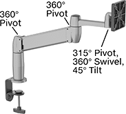
Set your monitor at nearly any angle. These mounts move up, down, and all around—just like your own arm. They’re easy to raise to eye level or swing around to share with a coworker. Tilt the mounting plate to reduce glare.
Gas Spring Balance—Fully offset your monitor’s weight for smooth, effortless adjustment in any direction.
Swivel Plate—Quickly rotate your monitor between portrait and landscape mode.
Load Cap., lb. | Projection | ||||||||||||||||
|---|---|---|---|---|---|---|---|---|---|---|---|---|---|---|---|---|---|
For Monitor Size | Min. | Max. | Display Ht. | Balance Mechanism | Min. | Max. | Material | For Max. Mounting Surface Thk. | Base Dia. | Monitor Mounting Pattern Compatibility | Mounting Fasteners Included | Adjustment Movement | Features | Each | |||
Clamp-On Base | |||||||||||||||||
| 10" to 24" | 7 | 20 | 7" to 14" | Gas Spring | 4" | 22" | Aluminum | 3 5/8" | 4" | VESA 75 × 75, VESA 100 × 100 | — | Extend, Pivot, Swivel, Tilt, Up and Down | Swivel Plate | 1993A5 | 0000000 | ||
Threaded-Hole Base | |||||||||||||||||
| 10" to 24" | 7 | 20 | 7" to 14" | Gas Spring | 4" | 22" | Aluminum | 2 1/4" | 4" | VESA 75 × 75, VESA 100 × 100 | Yes | Extend, Pivot, Swivel, Tilt, Up and Down | Swivel Plate | 1993A3 | 000000 | ||
Benchtop Monitor and Keyboard Mounts
Full Motion
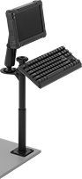 |  |
Screw-On Bench-Top Mount Shown Installed |
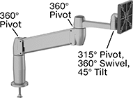
Set your monitor at nearly any angle. These mounts move up, down, and all around—just like your own arm. They’re easy to raise to eye level or swing around to share with a coworker. Tilt the mounting plate to reduce glare.
Swivel Plate—Quickly rotate your monitor between portrait and landscape mode.
Projection | Base | Mounting Pattern Compatibility | |||||||||||||
|---|---|---|---|---|---|---|---|---|---|---|---|---|---|---|---|
Max. Load Capacity | Display Ht. | Min. | Max. | Material | Lg. | Wd. | Monitor | Keyboard | Mounting Fasteners Included | Adjustment Movement | Features | Each | |||
Screw-On Base | |||||||||||||||
| 3 lb. | 9 3/4" to 28 1/4" | 6 5/8" | 19 3/4" | Black Powder-Coated Aluminum | 3 1/2" | 3 1/2" | VESA 75 × 75 | AMPS | Yes | Extend, Pivot, Swivel, Tilt, Up and Down | Swivel Plate | 6495N12 | 0000000 | ||
 |
Lg. | Wd. | Material | Attaching End Mounting Pattern Compatibility | Each | ||
|---|---|---|---|---|---|---|
| 3 1/2" | 3 1/2" | Powder-Coated Steel | AMPS, VESA 75 × 75 | 2005N15 | 000000 |
Suspension Positioning Arms for Enclosures
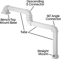 | 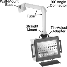 |
Example Configuration | All Components Sold Separately |
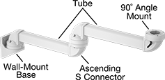 | |
Example Configuration |
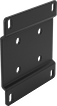
Bases
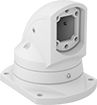 |
Bench Top |
Bases mount your arm to a surface.
Bench Top—Bench-top bases mount to horizontal surfaces, such as the top of a machine.
For Tube | Mounting Plate | ||||||||||||||
|---|---|---|---|---|---|---|---|---|---|---|---|---|---|---|---|
Adjustment Movement | Max. Range of Motion | Ht. | Wd. | Ht. | Lg. | Wd. | Hole Dia. | Material | Color | Mounting Fasteners Included | Features | Each | |||
Bench Top | |||||||||||||||
| Rotate | 310° | 3 1/2" | 2 1/2" | 7 1/4" | 7 3/4" | 5 3/4" | 0.433" | Powder-Coated Aluminum | White | Yes | Brake, Cable Routing Hole, Locking Pins, Swivels | 7255N11 | 0000000 | ||
