


Filter by
Body Material
Fitting Connection
For Use With
Fitting Material
Height
Drive Style
Filter Material
Maximum Flow Rate @ Pressure
Body Finish
Maximum Pressure
DFARS Specialty Metals
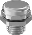
Breather Vents
 |  |
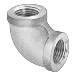
Style A | Style H |
Protect against excess vacuum and pressure in cylinders, gear boxes, enclosures, manifolds, and tanks. You can also use these breather vents to block debris from entering equipment.
Style H—Style H has a Buna-N O-ring for extra protection against leaks.
Style | Pipe Size | Thread Size | Max. Flow Rate @ Pressure | Max. Pressure, psi | Max. Temp., ° F | Ht. | For Use With | Removes Particle Size Down To, μm | Each | ||||||||||||||||||||||||||||||||||||||||||||||||||||||||||||||||||||||||||||||||||||||||||
|---|---|---|---|---|---|---|---|---|---|---|---|---|---|---|---|---|---|---|---|---|---|---|---|---|---|---|---|---|---|---|---|---|---|---|---|---|---|---|---|---|---|---|---|---|---|---|---|---|---|---|---|---|---|---|---|---|---|---|---|---|---|---|---|---|---|---|---|---|---|---|---|---|---|---|---|---|---|---|---|---|---|---|---|---|---|---|---|---|---|---|---|---|---|---|---|---|---|---|---|
NPT Male | |||||||||||||||||||||||||||||||||||||||||||||||||||||||||||||||||||||||||||||||||||||||||||||||||||
Zinc-Plated Steel Body and Fitting | |||||||||||||||||||||||||||||||||||||||||||||||||||||||||||||||||||||||||||||||||||||||||||||||||||
| A | 2 | — | 1,095 scfm @ 100 psi | 150 | 300 | 1 5/8" | Air, Inert Gas | 90 | 9833K16 | 000000 | |||||||||||||||||||||||||||||||||||||||||||||||||||||||||||||||||||||||||||||||||||||||||
Nickel-Plated Steel Body and Fitting | |||||||||||||||||||||||||||||||||||||||||||||||||||||||||||||||||||||||||||||||||||||||||||||||||||
| A | 1/8 | — | 2 scfm @ 100 psi | 150 | 300 | 7/16" | Air, Inert Gas | 40 | 9833K21 | 0000 | |||||||||||||||||||||||||||||||||||||||||||||||||||||||||||||||||||||||||||||||||||||||||
| A | 1/4 | — | 3 scfm @ 100 psi | 150 | 300 | 5/8" | Air, Inert Gas | 40 | 9833K22 | 0000 | |||||||||||||||||||||||||||||||||||||||||||||||||||||||||||||||||||||||||||||||||||||||||
| A | 3/8 | — | 7 scfm @ 100 psi | 150 | 300 | 3/4" | Air, Inert Gas | 40 | 9833K23 | 0000 | |||||||||||||||||||||||||||||||||||||||||||||||||||||||||||||||||||||||||||||||||||||||||
| A | 1/2 | — | 17 scfm @ 100 psi | 150 | 300 | 7/8" | Air, Inert Gas | 40 | 9833K11 | 0000 | |||||||||||||||||||||||||||||||||||||||||||||||||||||||||||||||||||||||||||||||||||||||||
| A | 3/4 | — | 20 scfm @ 100 psi | 150 | 300 | 1" | Air, Inert Gas | 40 | 9833K12 | 0000 | |||||||||||||||||||||||||||||||||||||||||||||||||||||||||||||||||||||||||||||||||||||||||
| A | 1 | — | 28 scfm @ 100 psi | 150 | 300 | 1 5/16" | Air, Inert Gas | 40 | 9833K13 | 0000 | |||||||||||||||||||||||||||||||||||||||||||||||||||||||||||||||||||||||||||||||||||||||||
| A | 1 1/4 | — | 50 scfm @ 100 psi | 150 | 300 | 1 7/16" | Air, Inert Gas | 40 | 9833K14 | 00000 | |||||||||||||||||||||||||||||||||||||||||||||||||||||||||||||||||||||||||||||||||||||||||
| A | 1 1/2 | — | 73 scfm @ 100 psi | 150 | 300 | 1 1/2" | Air, Inert Gas | 40 | 9833K15 | 00000 | |||||||||||||||||||||||||||||||||||||||||||||||||||||||||||||||||||||||||||||||||||||||||
Brass Body and Fitting | |||||||||||||||||||||||||||||||||||||||||||||||||||||||||||||||||||||||||||||||||||||||||||||||||||
| A | 1/16 | — | 13 scfm @ 100 psi | 150 | 300 | 1/2" | Air, Inert Gas | 90 | 9833K19 | 0000 | |||||||||||||||||||||||||||||||||||||||||||||||||||||||||||||||||||||||||||||||||||||||||
UNF Male | |||||||||||||||||||||||||||||||||||||||||||||||||||||||||||||||||||||||||||||||||||||||||||||||||||
Brass Body and Fitting | |||||||||||||||||||||||||||||||||||||||||||||||||||||||||||||||||||||||||||||||||||||||||||||||||||
| A | — | 10-32 | 6 scfm @ 100 psi | 150 | 300 | 3/8" | Air, Inert Gas | 90 | 9833K18 | 0000 | |||||||||||||||||||||||||||||||||||||||||||||||||||||||||||||||||||||||||||||||||||||||||
| H | — | 10-32 | 1 scfm @ 100 psi | 125 | 200 | 7/16" | Air, Inert Gas | 40 | 8556T24 | 0000 | |||||||||||||||||||||||||||||||||||||||||||||||||||||||||||||||||||||||||||||||||||||||||
BSPT Male | |||||||||||||||||||||||||||||||||||||||||||||||||||||||||||||||||||||||||||||||||||||||||||||||||||
Zinc-Plated Steel Body and Fitting | |||||||||||||||||||||||||||||||||||||||||||||||||||||||||||||||||||||||||||||||||||||||||||||||||||
| A | 1/8 | — | 26 scfm @ 100 psi | 150 | 300 | 7/16" | Air, Inert Gas | 90 | 9847K11 | 0000 | |||||||||||||||||||||||||||||||||||||||||||||||||||||||||||||||||||||||||||||||||||||||||
| A | 1/4 | — | 35 scfm @ 100 psi | 150 | 300 | 11/16" | Air, Inert Gas | 90 | 9847K12 | 0000 | |||||||||||||||||||||||||||||||||||||||||||||||||||||||||||||||||||||||||||||||||||||||||
| A | 3/8 | — | 87 scfm @ 100 psi | 150 | 300 | 13/16" | Air, Inert Gas | 90 | 9847K13 | 0000 | |||||||||||||||||||||||||||||||||||||||||||||||||||||||||||||||||||||||||||||||||||||||||
| A | 1/2 | — | 131 scfm @ 100 psi | 150 | 300 | 1" | Air, Inert Gas | 90 | 9847K14 | 0000 | |||||||||||||||||||||||||||||||||||||||||||||||||||||||||||||||||||||||||||||||||||||||||
| A | 3/4 | — | 219 scfm @ 100 psi | 150 | 300 | 1 1/16" | Air, Inert Gas | 90 | 9847K15 | 0000 | |||||||||||||||||||||||||||||||||||||||||||||||||||||||||||||||||||||||||||||||||||||||||
NPSM Female | |||||||||||||||||||||||||||||||||||||||||||||||||||||||||||||||||||||||||||||||||||||||||||||||||||
Zinc-Plated Steel Body and Fitting | |||||||||||||||||||||||||||||||||||||||||||||||||||||||||||||||||||||||||||||||||||||||||||||||||||
| F | 1/8 | — | 26 scfm @ 100 psi | 150 | 300 | 5/8" | Air, Inert Gas | 90 | 9833K24 | 0000 | |||||||||||||||||||||||||||||||||||||||||||||||||||||||||||||||||||||||||||||||||||||||||
| F | 1/4 | — | 35 scfm @ 100 psi | 150 | 300 | 3/4" | Air, Inert Gas | 90 | 9833K25 | 0000 | |||||||||||||||||||||||||||||||||||||||||||||||||||||||||||||||||||||||||||||||||||||||||
| F | 3/8 | — | 87 scfm @ 100 psi | 150 | 300 | 15/16" | Air, Inert Gas | 90 | 9833K26 | 0000 | |||||||||||||||||||||||||||||||||||||||||||||||||||||||||||||||||||||||||||||||||||||||||
| F | 1/2 | — | 131 scfm @ 100 psi | 150 | 300 | 1" | Air, Inert Gas | 90 | 9833K27 | 0000 | |||||||||||||||||||||||||||||||||||||||||||||||||||||||||||||||||||||||||||||||||||||||||
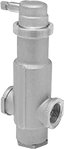
Self-Draining Breather Vents
Threaded NPT Male
 |
316 Stainless Steel Body and Fitting—316 stainless steel breather vents have excellent corrosion resistance.
Brass Body and Fitting—Brass breather vents have good corrosion resistance.
Pipe Size | Max. Flow Rate @ Pressure | Max. Pressure | Max. Temp., ° F | Ht. | Dia. | For Use With | Environment | Hazardous Location Protection Type | Enclosure Rating | Hazardous Location Rating | O-Ring Material | Certification | Features | Each | |||||||||||||||||||||||||||||||||||||||||||||||||||||||||||||||||||||||||||||||||||||
|---|---|---|---|---|---|---|---|---|---|---|---|---|---|---|---|---|---|---|---|---|---|---|---|---|---|---|---|---|---|---|---|---|---|---|---|---|---|---|---|---|---|---|---|---|---|---|---|---|---|---|---|---|---|---|---|---|---|---|---|---|---|---|---|---|---|---|---|---|---|---|---|---|---|---|---|---|---|---|---|---|---|---|---|---|---|---|---|---|---|---|---|---|---|---|---|---|---|---|---|
316 Stainless Steel Body and Fitting | |||||||||||||||||||||||||||||||||||||||||||||||||||||||||||||||||||||||||||||||||||||||||||||||||||
| 1/4 | Not Rated | Not Rated | 320 | 1 1/16" | 11/16" | Air | Corrosive, Dusty, Outdoor, Washdown, Wet | — | IP66, NEMA 4X | — | Silicone Rubber | — | Drain | 8602T31 | 000000 | ||||||||||||||||||||||||||||||||||||||||||||||||||||||||||||||||||||||||||||||||||||
| 1/2 | Not Rated | Not Rated | 320 | 1 1/8" | 1" | Air | Corrosive, Dusty, Hazardous, Outdoor, Washdown, Wet | Increased Safety, Protection by Enclosure | IP66, NEMA 4X | ATEX I M2 Ex E I Mb; ATEX II 2 GD Ex E IIC Gb Ex Tb IIIC Db; IEC Zone 1 Groups IIC, IIB, IIA; IEC Zone 21 Groups IIIC, IIIB, IIIA; IECEx Ex E I/IIC Mb/Gb; IECEx Ex IIIC Tb Db | Silicone Rubber | CE Marked | Drain | 8602T32 | 00000 | ||||||||||||||||||||||||||||||||||||||||||||||||||||||||||||||||||||||||||||||||||||
Brass Body and Fitting | |||||||||||||||||||||||||||||||||||||||||||||||||||||||||||||||||||||||||||||||||||||||||||||||||||
| 1/4 | Not Rated | Not Rated | 320 | 1 1/16" | 11/16" | Air | Corrosive, Dusty, Outdoor, Washdown, Wet | — | IP66, NEMA 4X | — | Silicone Rubber | — | Drain | 8602T11 | 00000 | ||||||||||||||||||||||||||||||||||||||||||||||||||||||||||||||||||||||||||||||||||||
| 1/2 | Not Rated | Not Rated | 320 | 1 1/8" | 1" | Air | Corrosive, Dusty, Hazardous, Outdoor, Washdown, Wet | Increased Safety, Protection by Enclosure | IP66, NEMA 4X | ATEX I M2 Ex E I Mb; ATEX II 2 GD Ex E IIC Gb Ex Tb IIIC Db; IEC Zone 1 Groups IIC, IIB, IIA; IEC Zone 21 Groups IIIC, IIIB, IIIA; IECEx Ex E I/IIC Mb/Gb; IECEx Ex IIIC Tb Db | Silicone Rubber | CE Marked | Drain | 8602T12 | 00000 | ||||||||||||||||||||||||||||||||||||||||||||||||||||||||||||||||||||||||||||||||||||
Submersible Threaded Breather Vents
Metric
 |
Nickel-Plated Brass |
Nickel-Plated Brass—Nickel-plated brass vents stand up to corrosive environments better than nylon and polycarbonate vents. They’re also durable, which means you won’t have to replace them as often.
Thread Size | Thread Pitch, mm | For Hole Dia. | Head Dia. | Environment | Enclosure Rating | Features | Each | ||||||||||||||||||||||||||||||||||||||||||||||||||||||||||||||||||||||||||||||||||||||||||||
|---|---|---|---|---|---|---|---|---|---|---|---|---|---|---|---|---|---|---|---|---|---|---|---|---|---|---|---|---|---|---|---|---|---|---|---|---|---|---|---|---|---|---|---|---|---|---|---|---|---|---|---|---|---|---|---|---|---|---|---|---|---|---|---|---|---|---|---|---|---|---|---|---|---|---|---|---|---|---|---|---|---|---|---|---|---|---|---|---|---|---|---|---|---|---|---|---|---|---|---|
Nickel-Plated Brass | |||||||||||||||||||||||||||||||||||||||||||||||||||||||||||||||||||||||||||||||||||||||||||||||||||
| M12 | 1.5 | 1/2" | 3/4" | Dusty, Submersible, Washdown, Wet | IP66, IP68 | Gasket | 4375N11 | 000000 | |||||||||||||||||||||||||||||||||||||||||||||||||||||||||||||||||||||||||||||||||||||||||||
| M16 | 1.5 | 5/8" | 3/4" | Dusty, Submersible, Washdown, Wet | IP66, IP68 | Gasket | 4375N12 | 00000 | |||||||||||||||||||||||||||||||||||||||||||||||||||||||||||||||||||||||||||||||||||||||||||
| M20 | 1.5 | 13/16" | 15/16" | Dusty, Submersible, Washdown, Wet | IP66, IP68 | Gasket | 4375N13 | 00000 | |||||||||||||||||||||||||||||||||||||||||||||||||||||||||||||||||||||||||||||||||||||||||||
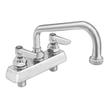
Air-Release Valves for Water and Coolant
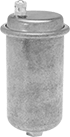
NPT Female Inlet, NPT Female Outlet and Relief Vent
 |
Inlet | Outlet | ||||||||||||||||||||||||||||||||||||||||||||||||||||||||||||||||||||||||||||||||||||||||||||||||||
|---|---|---|---|---|---|---|---|---|---|---|---|---|---|---|---|---|---|---|---|---|---|---|---|---|---|---|---|---|---|---|---|---|---|---|---|---|---|---|---|---|---|---|---|---|---|---|---|---|---|---|---|---|---|---|---|---|---|---|---|---|---|---|---|---|---|---|---|---|---|---|---|---|---|---|---|---|---|---|---|---|---|---|---|---|---|---|---|---|---|---|---|---|---|---|---|---|---|---|---|
Pipe Size | Location | Pipe Size | Location | Relief Port Location | Max. Pressure, psi | Temp. Range, ° F | Overall Ht. | Each | |||||||||||||||||||||||||||||||||||||||||||||||||||||||||||||||||||||||||||||||||||||||||||
Brass Body—Vertical Mount | |||||||||||||||||||||||||||||||||||||||||||||||||||||||||||||||||||||||||||||||||||||||||||||||||||
| 1/8 | Bottom | 1/8 | Side | Top | 75 | 33 to 240 | 4 3/8" | 4928K2 | 000000 | ||||||||||||||||||||||||||||||||||||||||||||||||||||||||||||||||||||||||||||||||||||||||||
NPT Female/Male Inlet and Relief Vent
 |
Inlet | |||||||||||||||||||||||||||||||||||||||||||||||||||||||||||||||||||||||||||||||||||||||||||||||||||
|---|---|---|---|---|---|---|---|---|---|---|---|---|---|---|---|---|---|---|---|---|---|---|---|---|---|---|---|---|---|---|---|---|---|---|---|---|---|---|---|---|---|---|---|---|---|---|---|---|---|---|---|---|---|---|---|---|---|---|---|---|---|---|---|---|---|---|---|---|---|---|---|---|---|---|---|---|---|---|---|---|---|---|---|---|---|---|---|---|---|---|---|---|---|---|---|---|---|---|---|
Female Pipe Size | Male Pipe Size | Location | Relief Port Location | Max. Pressure, psi | Temp. Range, ° F | Overall Ht. | Each | ||||||||||||||||||||||||||||||||||||||||||||||||||||||||||||||||||||||||||||||||||||||||||||
Brass Body—Vertical Mount | |||||||||||||||||||||||||||||||||||||||||||||||||||||||||||||||||||||||||||||||||||||||||||||||||||
| 1/2 | 3/4 | Bottom | Top | 150 | 33 to 240 | 4 3/4" | 4928K4 | 000000 | |||||||||||||||||||||||||||||||||||||||||||||||||||||||||||||||||||||||||||||||||||||||||||
NPT Male Inlet and Relief Vent
 |
Inlet | |||||||||||||||||||||||||||||||||||||||||||||||||||||||||||||||||||||||||||||||||||||||||||||||||||
|---|---|---|---|---|---|---|---|---|---|---|---|---|---|---|---|---|---|---|---|---|---|---|---|---|---|---|---|---|---|---|---|---|---|---|---|---|---|---|---|---|---|---|---|---|---|---|---|---|---|---|---|---|---|---|---|---|---|---|---|---|---|---|---|---|---|---|---|---|---|---|---|---|---|---|---|---|---|---|---|---|---|---|---|---|---|---|---|---|---|---|---|---|---|---|---|---|---|---|---|
Pipe Size | Location | Relief Port Location | Max. Pressure, psi | Temp. Range, ° F | Overall Ht. | Each | |||||||||||||||||||||||||||||||||||||||||||||||||||||||||||||||||||||||||||||||||||||||||||||
Brass Body—Vertical Mount | |||||||||||||||||||||||||||||||||||||||||||||||||||||||||||||||||||||||||||||||||||||||||||||||||||
| 1/8 | Bottom | Top | 50 | 33 to 240 | 2 5/8" | 4928K11 | 000000 | ||||||||||||||||||||||||||||||||||||||||||||||||||||||||||||||||||||||||||||||||||||||||||||
| 1/8 | Bottom | Top | 50 | 33 to 240 | 3 3/4" | 4928K12 | 00000 | ||||||||||||||||||||||||||||||||||||||||||||||||||||||||||||||||||||||||||||||||||||||||||||
| 1/8 | Bottom | Top | 75 | 33 to 240 | 4 3/8" | 4928K8 | 00000 | ||||||||||||||||||||||||||||||||||||||||||||||||||||||||||||||||||||||||||||||||||||||||||||
| 1/4 | Bottom | Top | 50 | 33 to 240 | 4" | 4928K13 | 00000 | ||||||||||||||||||||||||||||||||||||||||||||||||||||||||||||||||||||||||||||||||||||||||||||
| 1/4 | Bottom | Top | 150 | 33 to 240 | 4 3/4" | 4928K9 | 00000 | ||||||||||||||||||||||||||||||||||||||||||||||||||||||||||||||||||||||||||||||||||||||||||||
| 1/2 | Bottom | Top | 150 | 33 to 240 | 3 3/8" | 4928K16 | 00000 | ||||||||||||||||||||||||||||||||||||||||||||||||||||||||||||||||||||||||||||||||||||||||||||
| 3/4 | Bottom | Top | 150 | 33 to 240 | 3 3/8" | 4928K17 | 00000 | ||||||||||||||||||||||||||||||||||||||||||||||||||||||||||||||||||||||||||||||||||||||||||||
| 1 | Bottom | Top | 150 | 33 to 240 | 3 1/2" | 4928K18 | 00000 | ||||||||||||||||||||||||||||||||||||||||||||||||||||||||||||||||||||||||||||||||||||||||||||
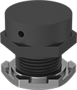
Hazardous Location Electrical Enclosure Drain Vents
 |
Glass-Filled Nylon |
Safe for use around hazardous gasses and dust, these drain vents maintain steady pressure and prevent moisture buildup from temperature changes inside enclosures. They allow air to flow through the enclosures while protecting the contents from washdowns, dirt, and weather. Install these drain vents at the lowest point on an enclosure, so moisture can drip out.
Increased Safety—Increased-safety drain vents keep sparks, high temperatures, or current creepage inside an enclosure, so they won’t ignite flammable gasses and dust.
Glass-Filled Nylon—Glass-filled nylon drain vents are lightweight yet durable. They’re good for most areas.
Thread Size | Ht. | Enclosure Rating | Nut Material | O-Ring Material | Color | Max. Temp., ° F | Hazardous Location Rating | Each | |||||||||||||||||||||||||||||||||||||||||||||||||||||||||||||||||||||||||||||||||||||||||||
|---|---|---|---|---|---|---|---|---|---|---|---|---|---|---|---|---|---|---|---|---|---|---|---|---|---|---|---|---|---|---|---|---|---|---|---|---|---|---|---|---|---|---|---|---|---|---|---|---|---|---|---|---|---|---|---|---|---|---|---|---|---|---|---|---|---|---|---|---|---|---|---|---|---|---|---|---|---|---|---|---|---|---|---|---|---|---|---|---|---|---|---|---|---|---|---|---|---|---|---|
Increased-Safety Drain Vents | |||||||||||||||||||||||||||||||||||||||||||||||||||||||||||||||||||||||||||||||||||||||||||||||||||
Glass-Filled Nylon | |||||||||||||||||||||||||||||||||||||||||||||||||||||||||||||||||||||||||||||||||||||||||||||||||||
| M20 × 1.5 mm | 1 1/4" | NEMA 4X, IP66 | Brass | Buna-N | Black | 185 | ATEX II 2DG IECEx Ex Tb IIIC Db IECEx Exe II Gb NEC Class I Division 2 Groups A, B, C, D | 5901N15 | 000000 | ||||||||||||||||||||||||||||||||||||||||||||||||||||||||||||||||||||||||||||||||||||||||||
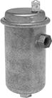
Inline Air-Release Valves for Water
 |
Eliminate air pockets without stopping flow—these valves have an internal wire brush that traps air bubbles and discharges them through the top relief port while allowing inline flow from the inlet to the outlet. They are often used to increase efficiency in heating and cooling systems. The vented relief port exhausts discharge directly. Valves have a durable bronze body for a long service life.
Inlet | Outlet | ||||||||||||||||||||||||||||||||||||||||||||||||||||||||||||||||||||||||||||||||||||||||||||||||||
|---|---|---|---|---|---|---|---|---|---|---|---|---|---|---|---|---|---|---|---|---|---|---|---|---|---|---|---|---|---|---|---|---|---|---|---|---|---|---|---|---|---|---|---|---|---|---|---|---|---|---|---|---|---|---|---|---|---|---|---|---|---|---|---|---|---|---|---|---|---|---|---|---|---|---|---|---|---|---|---|---|---|---|---|---|---|---|---|---|---|---|---|---|---|---|---|---|---|---|---|
Pipe Size | Location | Pipe Size | Location | Relief Port Location | Max. Pressure, psi | Temp. Range, ° F | Overall Ht. | End-to-End Lg. | Each | ||||||||||||||||||||||||||||||||||||||||||||||||||||||||||||||||||||||||||||||||||||||||||
NPT Female Inlet, NPT Female Outlet and Relief Vent | |||||||||||||||||||||||||||||||||||||||||||||||||||||||||||||||||||||||||||||||||||||||||||||||||||
Bronze Body—Vertical Mount | |||||||||||||||||||||||||||||||||||||||||||||||||||||||||||||||||||||||||||||||||||||||||||||||||||
| 3/4 | Side | 3/4 | Side | Top | 125 | 40 to 240 | 6 15/16" | 2 11/16" | 4742T11 | 0000000 | |||||||||||||||||||||||||||||||||||||||||||||||||||||||||||||||||||||||||||||||||||||||||
| 1 | Side | 1 | Side | Top | 125 | 40 to 240 | 6 1/2" | 3 1/8" | 4742T12 | 000000 | |||||||||||||||||||||||||||||||||||||||||||||||||||||||||||||||||||||||||||||||||||||||||
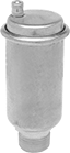
Air-Release Valves for Steam
 |
Inlet | |||||||||||||||||||||||||||||||||||||||||||||||||||||||||||||||||||||||||||||||||||||||||||||||||||
|---|---|---|---|---|---|---|---|---|---|---|---|---|---|---|---|---|---|---|---|---|---|---|---|---|---|---|---|---|---|---|---|---|---|---|---|---|---|---|---|---|---|---|---|---|---|---|---|---|---|---|---|---|---|---|---|---|---|---|---|---|---|---|---|---|---|---|---|---|---|---|---|---|---|---|---|---|---|---|---|---|---|---|---|---|---|---|---|---|---|---|---|---|---|---|---|---|---|---|---|
Max. Steam Pressure, psi | Pipe Size | Location | Relief Port Location | Max. Temp., ° F | Overall Ht. | Each | |||||||||||||||||||||||||||||||||||||||||||||||||||||||||||||||||||||||||||||||||||||||||||||
NPT Male Relief Vent | |||||||||||||||||||||||||||||||||||||||||||||||||||||||||||||||||||||||||||||||||||||||||||||||||||
Brass Body | |||||||||||||||||||||||||||||||||||||||||||||||||||||||||||||||||||||||||||||||||||||||||||||||||||
| 15 | 3/4 | Bottom | Top | 250 | 3 1/2" | 4926K52 | 000000 | ||||||||||||||||||||||||||||||||||||||||||||||||||||||||||||||||||||||||||||||||||||||||||||
Key-Operated Air-Release Valves for Water
