


Filter by
Current
Mounting Location
Manufacturer
Wire Connection


Breakthrough Current @ Voltage
Circuit Breaker Interruption Type
Manual Reset Style
Electrical Connection
Specifications Met
DFARS Specialty Metals
Reset Type
Export Control Classification Number (ECCN)
Environment
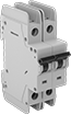
Square D Load-Center Circuit Breakers
QO Series
 |
QO Series, 2 Poles |
UL 489—They meet UL 489 requirements for branch circuit protection, so they protect downstream equipment and wiring from overloads and short circuits.
Breakthrough Current @ Voltage—Breakthrough current is the maximum current that the circuit breaker can safely stop in the event of a short circuit.
Current, A | Voltage | Freq., Hz | Breakthrough Current @ Voltage | Mounting Location | Wire Connection Method | Wd. | Specs. Met | Certification | Each | ||||||||||||||||||||||||||||||||||||||||||||||||||||||||||||||||||||||||||||||||||||||||||
|---|---|---|---|---|---|---|---|---|---|---|---|---|---|---|---|---|---|---|---|---|---|---|---|---|---|---|---|---|---|---|---|---|---|---|---|---|---|---|---|---|---|---|---|---|---|---|---|---|---|---|---|---|---|---|---|---|---|---|---|---|---|---|---|---|---|---|---|---|---|---|---|---|---|---|---|---|---|---|---|---|---|---|---|---|---|---|---|---|---|---|---|---|---|---|---|---|---|---|---|
2 Poles—Toggle Switch | |||||||||||||||||||||||||||||||||||||||||||||||||||||||||||||||||||||||||||||||||||||||||||||||||||
| 50 | 48V DC 120V AC 240V AC | 50/60 | 10,000 amp @ 120V AC 10,000 amp @ 240V AC 5,000 amp @ 48V DC | Breaker Box | Snap On | 1 1/2" | UL 489 | UL Listed | 6782K216 | 000000 | |||||||||||||||||||||||||||||||||||||||||||||||||||||||||||||||||||||||||||||||||||||||||
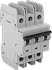
QOB Series
 |
QOB Series, 3 Poles |
UL 489—They meet UL 489 requirements for branch circuit protection, so they protect downstream equipment and wiring from overloads and short circuits.
Breakthrough Current @ Voltage—Breakthrough current is the maximum current that the circuit breaker can safely stop in the event of a short circuit.
Current, A | Voltage | Freq., Hz | Breakthrough Current @ Voltage | Mounting Location | Wire Connection | Wd. | Specs. Met | Certification | Each | ||||||||||||||||||||||||||||||||||||||||||||||||||||||||||||||||||||||||||||||||||||||||||
|---|---|---|---|---|---|---|---|---|---|---|---|---|---|---|---|---|---|---|---|---|---|---|---|---|---|---|---|---|---|---|---|---|---|---|---|---|---|---|---|---|---|---|---|---|---|---|---|---|---|---|---|---|---|---|---|---|---|---|---|---|---|---|---|---|---|---|---|---|---|---|---|---|---|---|---|---|---|---|---|---|---|---|---|---|---|---|---|---|---|---|---|---|---|---|---|---|---|---|---|
3 Poles—Toggle Switch | |||||||||||||||||||||||||||||||||||||||||||||||||||||||||||||||||||||||||||||||||||||||||||||||||||
| 50 | 48V DC 120V AC 240V AC | 50/60 | 10,000 amp @ 120V AC 10,000 amp @ 240V AC 5,000 amp @ 48V DC | Panel Board | Screw-Clamp Terminal | 2 1/4" | UL 489 | UL Listed | 6782K313 | 0000000 | |||||||||||||||||||||||||||||||||||||||||||||||||||||||||||||||||||||||||||||||||||||||||
Homeline Series
 |  |
Homeline Series, 1 Pole | Homeline Series, 3 Poles |
UL 489—They meet UL 489 requirements for branch circuit protection, so they protect downstream equipment and wiring from overloads and short circuits.
Breakthrough Current @ Voltage—Breakthrough current is the maximum current that the circuit breaker can safely stop in the event of a short circuit.
Current, A | Voltage, V AC | Freq., Hz | Breakthrough Current @ Voltage | Mounting Location | Wire Connection Method | Wd. | Specs. Met | Certification | Each | ||||||||||||||||||||||||||||||||||||||||||||||||||||||||||||||||||||||||||||||||||||||||||
|---|---|---|---|---|---|---|---|---|---|---|---|---|---|---|---|---|---|---|---|---|---|---|---|---|---|---|---|---|---|---|---|---|---|---|---|---|---|---|---|---|---|---|---|---|---|---|---|---|---|---|---|---|---|---|---|---|---|---|---|---|---|---|---|---|---|---|---|---|---|---|---|---|---|---|---|---|---|---|---|---|---|---|---|---|---|---|---|---|---|---|---|---|---|---|---|---|---|---|---|
1 Pole—Toggle-Switch Style | |||||||||||||||||||||||||||||||||||||||||||||||||||||||||||||||||||||||||||||||||||||||||||||||||||
| 50 | 120 240 | 50/60 | 10,000 amp @ 120V AC 10,000 amp @ 240V AC | Breaker Box | Snap On | 1" | UL 489 | UL Listed | 69225K101 | 000000 | |||||||||||||||||||||||||||||||||||||||||||||||||||||||||||||||||||||||||||||||||||||||||
2 Poles—Toggle Switch | |||||||||||||||||||||||||||||||||||||||||||||||||||||||||||||||||||||||||||||||||||||||||||||||||||
| 50 | 120 240 | 50/60 | 10,000 amp @ 120V AC 10,000 amp @ 240V AC | Breaker Box | Snap On | 2" | UL 489 | UL Listed | 69225K102 | 00000 | |||||||||||||||||||||||||||||||||||||||||||||||||||||||||||||||||||||||||||||||||||||||||
DIN-Rail Mount Equipment Circuit Breakers
 |
 |  |  |
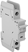
Auxiliary Contact | Distribution Bar | Distribution Bar Terminal Cover |
 |  |  |
Distribution Bar End Cover | Shunt Trip | Extension Terminal |
Distribution bars simplify wiring by powering multiple adjacent circuit breakers without needing separate wires for each one. This cuts down on assembly time and space. Cut them to the number of terminals that you need.
Distribution bar terminal covers shield unused, live terminals on distribution bars to prevent injury and damage.
Auxiliary contacts send a signal to other equipment when the circuit trips. They can activate a warning light, initiate a shutdown, or start a backup power source.
Shunt trips receive a signal from equipment to trip your circuit breaker in situations other than overload or short circuit conditions. For example, use them with a smoke detector to shut off power to a system in the event of a fire.
Extension terminals raise the wire connection point above distribution bars for easy access to connect power to a set of circuit breakers.
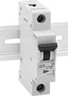
Also known as supplemental protectors, these circuit breakers mount directly to DIN rail downstream from a branch circuit breaker to protect a single piece of equipment. Because they are thermal-magnetic, these breakers trip two ways. They either trip when heat is generated slowly by consistent low-level overload current, or they trip quickly when the magnetic coil senses a high-current short circuit.
Distribution bar end covers seal the live ends of distribution bars to prevent injury and damage.
C Trip
 |  |  |
1 Pole—Toggle-Switch Style | 2 Poles—Toggle-Switch Style | 3 Poles—Toggle-Switch Style |
C-trip circuit breakers are the most common. They’re best for applications such as lighting and control panels, where equipment startup causes a moderate spike in current. They won’t trip until a rush of current reaches 5 to 10 times their rated current.
UL 1077—They are rated UL 1077 for protection against overloads and short circuits.
Current, A | Voltage | Freq., Hz | Breakthrough Current @ Voltage | For DIN Rail Size, mm | Mounting Location | Wire Connection | Ht. | Wd. | Dp. | Temp. Range, ° F | Specs. Met | Certification | Each | ||||||||||||||||||||||||||||||||||||||||||||||||||||||||||||||||||||||||||||||||||||||
|---|---|---|---|---|---|---|---|---|---|---|---|---|---|---|---|---|---|---|---|---|---|---|---|---|---|---|---|---|---|---|---|---|---|---|---|---|---|---|---|---|---|---|---|---|---|---|---|---|---|---|---|---|---|---|---|---|---|---|---|---|---|---|---|---|---|---|---|---|---|---|---|---|---|---|---|---|---|---|---|---|---|---|---|---|---|---|---|---|---|---|---|---|---|---|---|---|---|---|---|
1 Pole—Toggle-Switch Style | |||||||||||||||||||||||||||||||||||||||||||||||||||||||||||||||||||||||||||||||||||||||||||||||||||
Thermal/Magnetic | |||||||||||||||||||||||||||||||||||||||||||||||||||||||||||||||||||||||||||||||||||||||||||||||||||
| 50 | 48V DC 277V AC | 50/60 | 5,000 amp @ 277V AC 5,000 amp @ 48V DC | 35 | DIN Rail | Screw-Clamp Terminal | 3.15" | 0.7" | 2.36" | -40 to 165 | UL 1077, IEC 60947-2 | UL Listed, CSA Certified, CE Marked | 7026K632 | 000000 | |||||||||||||||||||||||||||||||||||||||||||||||||||||||||||||||||||||||||||||||||||||
2 Poles—Toggle-Switch Style | |||||||||||||||||||||||||||||||||||||||||||||||||||||||||||||||||||||||||||||||||||||||||||||||||||
Thermal/Magnetic | |||||||||||||||||||||||||||||||||||||||||||||||||||||||||||||||||||||||||||||||||||||||||||||||||||
| 50 | 96V DC 277V AC 480YV AC/277V AC | 50/60 | 5,000 amp @ 277V AC 5,000 amp @ 480V AC 5,000 amp @ 96V DC | 35 | DIN Rail | Screw-Clamp Terminal | 3.15" | 1.4" | 2.36" | -40 to 165 | UL 1077, IEC 60947-2 | UL Listed, CSA Certified, CE Marked | 7026K641 | 000000 | |||||||||||||||||||||||||||||||||||||||||||||||||||||||||||||||||||||||||||||||||||||
3 Poles—Toggle-Switch Style | |||||||||||||||||||||||||||||||||||||||||||||||||||||||||||||||||||||||||||||||||||||||||||||||||||
Thermal/Magnetic | |||||||||||||||||||||||||||||||||||||||||||||||||||||||||||||||||||||||||||||||||||||||||||||||||||
| 50 | 277V AC 480YV AC/277V AC | 50/60 | 5,000 amp @ 277V AC 5,000 amp @ 480V AC | 35 | DIN Rail | Screw-Clamp Terminal | 3.15" | 2.09" | 2.36" | -40 to 165 | UL 1077, IEC 60947-2 | UL Listed, CSA Certified, CE Marked | 7026K87 | 000000 | |||||||||||||||||||||||||||||||||||||||||||||||||||||||||||||||||||||||||||||||||||||
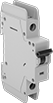
D Trip
| | |
1 Pole—Toggle-Switch Style | 2 Poles—Toggle-Switch Style | 3 Poles—Toggle-Switch Style |
D-trip circuit breakers prevent nuisance tripping, so they are best for equipment that has a high spike in current at startup, such as transformers, power supplies, and heaters. They will not trip unless a rush of current reaches 10 to 20 times their rated current.
UL 1077—They are rated UL 1077 for protection against overloads and short circuits.
Current, A | Voltage | Freq., Hz | Breakthrough Current @ Voltage | For DIN Rail Size, mm | Mounting Location | Wire Connection | Ht. | Wd. | Dp. | Temp. Range, ° F | Specs. Met | Certification | Each | ||||||||||||||||||||||||||||||||||||||||||||||||||||||||||||||||||||||||||||||||||||||
|---|---|---|---|---|---|---|---|---|---|---|---|---|---|---|---|---|---|---|---|---|---|---|---|---|---|---|---|---|---|---|---|---|---|---|---|---|---|---|---|---|---|---|---|---|---|---|---|---|---|---|---|---|---|---|---|---|---|---|---|---|---|---|---|---|---|---|---|---|---|---|---|---|---|---|---|---|---|---|---|---|---|---|---|---|---|---|---|---|---|---|---|---|---|---|---|---|---|---|---|
1 Pole—Toggle-Switch Style | |||||||||||||||||||||||||||||||||||||||||||||||||||||||||||||||||||||||||||||||||||||||||||||||||||
Thermal/Magnetic | |||||||||||||||||||||||||||||||||||||||||||||||||||||||||||||||||||||||||||||||||||||||||||||||||||
| 50 | 48V DC 277V AC | 50/60 | 5,000 amp @ 277V AC 5,000 amp @ 48V DC | 35 | DIN Rail | Screw-Clamp Terminal | 3.15" | 0.7" | 2.36" | -40 to 165 | UL 1077, IEC 60947-2 | UL Listed, CSA Certified, CE Marked | 7026K655 | 000000 | |||||||||||||||||||||||||||||||||||||||||||||||||||||||||||||||||||||||||||||||||||||
2 Poles—Toggle-Switch Style | |||||||||||||||||||||||||||||||||||||||||||||||||||||||||||||||||||||||||||||||||||||||||||||||||||
Thermal/Magnetic | |||||||||||||||||||||||||||||||||||||||||||||||||||||||||||||||||||||||||||||||||||||||||||||||||||
| 50 | 96V DC 277V AC 480YV AC/277V AC | 50/60 | 5,000 amp @ 277V AC 5,000 amp @ 480V AC 5,000 amp @ 96V DC | 35 | DIN Rail | Screw-Clamp Terminal | 3.15" | 1.4" | 2.36" | -40 to 165 | UL 1077, IEC 60947-2 | UL Listed, CSA Certified, CE Marked | 7026K662 | 000000 | |||||||||||||||||||||||||||||||||||||||||||||||||||||||||||||||||||||||||||||||||||||
3 Poles—Toggle-Switch Style | |||||||||||||||||||||||||||||||||||||||||||||||||||||||||||||||||||||||||||||||||||||||||||||||||||
Thermal/Magnetic | |||||||||||||||||||||||||||||||||||||||||||||||||||||||||||||||||||||||||||||||||||||||||||||||||||
| 50 | 277V AC 480YV AC/277V AC | 50/60 | 5,000 amp @ 277V AC 5,000 amp @ 480V AC | 35 | DIN Rail | Screw-Clamp Terminal | 3.15" | 2.09" | 2.36" | -40 to 165 | UL 1077, IEC 60947-2 | UL Listed, CSA Certified, CE Marked | 7026K669 | 000000 | |||||||||||||||||||||||||||||||||||||||||||||||||||||||||||||||||||||||||||||||||||||
DIN-Rail Mount Branch Circuit Breakers
 |
 | | |
Extension Terminal | Distribution Bar Terminal Cover | Shunt Trip |
 |  | |
Auxiliary Contact | Distribution Bar |
Distribution bar terminal covers shield unused, live terminals on distribution bars to prevent injury and damage.
Auxiliary contacts send a signal to other equipment when the circuit trips. They can activate a warning light, initiate a shutdown, or start a backup power source.
Shunt trips receive a signal from equipment to trip your circuit breaker in situations other than overload or short circuit conditions. For example, use them with a smoke detector to shut off power to a system in the event of a fire.
Extension terminals raise the wire connection point above distribution bars for easy access to connect power to a set of circuit breakers.
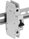
Mount these circuit breakers directly to DIN rail to protect equipment and wiring in an area of your facility from overloads and short circuits. Because they are thermal-magnetic, these breakers trip two ways. They either trip when heat is generated slowly by consistent low-level overload current, or they trip quickly when the magnetic coil senses a high-current short circuit.
Distribution bars simplify wiring by powering multiple adjacent circuit breakers without needing separate wires for each one. This cuts down on assembly time and space.
C Trip
 |  |  |
1 Pole—Toggle-Switch Style | 2 Poles—Toggle-Switch Style | 3 Poles—Toggle-Switch Style |
C-trip circuit breakers are the most common. They’re best for applications such as lighting and control panels, where equipment startup causes a moderate spike in current. They won’t trip until a rush of current reaches 5 to 10 times their rated current.
UL 489—They meet UL 489 requirements for branch circuit protection and are certified as current limiting, so they protect equipment by minimizing passing current during a short circuit.
Breakthrough Current @ Voltage—Breakthrough current is the maximum current that the circuit breaker can safely stop in the event of a short circuit.
Voltage | Freq., Hz | Breakthrough Current @ Voltage | For DIN Rail Size, mm | Mounting Location | Wire Connection | Ht. | Wd. | Dp. | Temp. Range, ° F | Specs. Met | Certification | Current, A | Each | ||||||||||||||||||||||||||||||||||||||||||||||||||||||||||||||||||||||||||||||||||||||
|---|---|---|---|---|---|---|---|---|---|---|---|---|---|---|---|---|---|---|---|---|---|---|---|---|---|---|---|---|---|---|---|---|---|---|---|---|---|---|---|---|---|---|---|---|---|---|---|---|---|---|---|---|---|---|---|---|---|---|---|---|---|---|---|---|---|---|---|---|---|---|---|---|---|---|---|---|---|---|---|---|---|---|---|---|---|---|---|---|---|---|---|---|---|---|---|---|---|---|---|
1 Pole—Toggle-Switch Style | |||||||||||||||||||||||||||||||||||||||||||||||||||||||||||||||||||||||||||||||||||||||||||||||||||
Thermal/Magnetic | |||||||||||||||||||||||||||||||||||||||||||||||||||||||||||||||||||||||||||||||||||||||||||||||||||
| 48V DC 240V AC | 50/60 | 10,000 amp @ 240V AC 10,000 amp @ 48V DC | 35 | DIN Rail | Screw-Clamp Terminal | 4.13" | 0.7" | 2.36" | -10 to 165 | UL 489, IEC 60947-2 | CSA Certified, CE Marked | 50 | 5789T204 | 000000 | |||||||||||||||||||||||||||||||||||||||||||||||||||||||||||||||||||||||||||||||||||||
2 Poles—Toggle-Switch Style | |||||||||||||||||||||||||||||||||||||||||||||||||||||||||||||||||||||||||||||||||||||||||||||||||||
Thermal/Magnetic | |||||||||||||||||||||||||||||||||||||||||||||||||||||||||||||||||||||||||||||||||||||||||||||||||||
| 96V DC 240V AC | 50/60 | 10,000 amp @ 240V AC 10,000 amp @ 96V DC | 35 | DIN Rail | Screw-Clamp Terminal | 4.13" | 1.4" | 2.36" | -10 to 165 | UL 489, IEC 60947-2 | CSA Certified, CE Marked | 50 | 5789T206 | 00000 | |||||||||||||||||||||||||||||||||||||||||||||||||||||||||||||||||||||||||||||||||||||
3 Poles—Toggle-Switch Style | |||||||||||||||||||||||||||||||||||||||||||||||||||||||||||||||||||||||||||||||||||||||||||||||||||
Thermal/Magnetic | |||||||||||||||||||||||||||||||||||||||||||||||||||||||||||||||||||||||||||||||||||||||||||||||||||
| 240V AC | 50/60 | 10,000 amp @ 240V AC | 35 | DIN Rail | Screw-Clamp Terminal | 4.13" | 2.09" | 2.36" | -10 to 165 | UL 489, IEC 60947-2 | CSA Certified, CE Marked | 50 | 5789T208 | 000000 | |||||||||||||||||||||||||||||||||||||||||||||||||||||||||||||||||||||||||||||||||||||
Siemens Load-Center Circuit Breakers
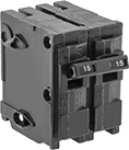 |
2 Poles—Toggle-Switch Style |
Use with Siemens EQ series breaker boxes. Because they are thermal-magnetic, these circuit breakers trip two different ways. They either trip when heat is generated slowly by consistent low-level overload current or quickly when the magnetic coil senses a high-current short circuit.
UL 489—These circuit breakers meet UL 489 requirements for branch circuit protection, so they protect downstream equipment and wiring from overloads and short circuits.
Breakthrough Current @ Voltage—Breakthrough current is the maximum current that the circuit breaker can safely stop in the event of a short circuit.
Current, A | Voltage, V AC | Freq., Hz | Breakthrough Current @ Voltage | Mounting Location | Wire Connection | Wd. | Specs. Met | Each | |||||||||||||||||||||||||||||||||||||||||||||||||||||||||||||||||||||||||||||||||||||||||||
|---|---|---|---|---|---|---|---|---|---|---|---|---|---|---|---|---|---|---|---|---|---|---|---|---|---|---|---|---|---|---|---|---|---|---|---|---|---|---|---|---|---|---|---|---|---|---|---|---|---|---|---|---|---|---|---|---|---|---|---|---|---|---|---|---|---|---|---|---|---|---|---|---|---|---|---|---|---|---|---|---|---|---|---|---|---|---|---|---|---|---|---|---|---|---|---|---|---|---|---|
2 Poles—Toggle-Switch Style | |||||||||||||||||||||||||||||||||||||||||||||||||||||||||||||||||||||||||||||||||||||||||||||||||||
Thermal/Magnetic | |||||||||||||||||||||||||||||||||||||||||||||||||||||||||||||||||||||||||||||||||||||||||||||||||||
| 50 | 120 240 | 60 | 10,000 amp @ 120V AC 10,000 amp @ 240V AC | Breaker Box | Screw-Clamp Terminal | 2" | UL 489 | 5259T55 | 000000 | ||||||||||||||||||||||||||||||||||||||||||||||||||||||||||||||||||||||||||||||||||||||||||
Cutler-Hammer Load-Center Circuit Breakers
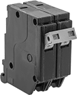 |
2 Poles—Toggle-Switch Style |
Install these circuit breakers into Cutler-Hammer CH series breaker boxes. Because these circuit breakers are thermal-magnetic, they trip two different ways. They either trip when heat is generated slowly by consistent low-level overload current or quickly when the magnetic coil senses a high-current short circuit.
UL 489—They meet UL 489 requirements for branch circuit protection and are certified as current limiting, so they protect equipment by minimizing passing current during a short circuit.
Breakthrough Current @ Voltage—Breakthrough current is the maximum current that the circuit breaker can safely stop in the event of a short circuit.
Current, A | Voltage, V AC | Freq., Hz | Breakthrough Current @ Voltage | Mounting Location | Wire Connection | Wd. | Specs. Met | Each | |||||||||||||||||||||||||||||||||||||||||||||||||||||||||||||||||||||||||||||||||||||||||||
|---|---|---|---|---|---|---|---|---|---|---|---|---|---|---|---|---|---|---|---|---|---|---|---|---|---|---|---|---|---|---|---|---|---|---|---|---|---|---|---|---|---|---|---|---|---|---|---|---|---|---|---|---|---|---|---|---|---|---|---|---|---|---|---|---|---|---|---|---|---|---|---|---|---|---|---|---|---|---|---|---|---|---|---|---|---|---|---|---|---|---|---|---|---|---|---|---|---|---|---|
2 Poles—Toggle-Switch Style | |||||||||||||||||||||||||||||||||||||||||||||||||||||||||||||||||||||||||||||||||||||||||||||||||||
Thermal/Magnetic | |||||||||||||||||||||||||||||||||||||||||||||||||||||||||||||||||||||||||||||||||||||||||||||||||||
| 50 | 120 240 | 60 | 10,000 amp @ 120V AC 10,000 amp @ 240V AC | Breaker Box | Screw-Clamp Terminal | 1 1/2" | UL 489 | 5259T85 | 000000 | ||||||||||||||||||||||||||||||||||||||||||||||||||||||||||||||||||||||||||||||||||||||||||
Harsh-Environment Circuit Breakers
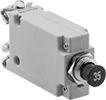 |  |  |
1 Pole—Push-Pull-Button Style | 1 Pole—Lever Style | 1 Pole—Push-Button Style |
Built to resist vibration and corrosion in harsh environments, these circuit breakers protect against overload and short circuits in low-voltage automotive and other electronic applications. All are thermal, so they use the heat generated in overcurrent situations to trip the breaker.
Lever Manual Reset and Push-Pull Button Manual Reset—Push-pull button and lever style breakers can be used as an on/off switch.
UL 1077—Place UL 1077-rated breakers downstream from a branch circuit breaker to protect a single piece of equipment. They are also known as supplemental protectors.
Breakthrough Current @ Voltage—Breakthrough current is the maximum current that the circuit breaker can safely stop in the event of a short circuit.
Mounting Holes | Screw On | ||||||||||||||||||||||||||||||||||||||||||||||||||||||||||||||||||||||||||||||||||||||||||||||||||
|---|---|---|---|---|---|---|---|---|---|---|---|---|---|---|---|---|---|---|---|---|---|---|---|---|---|---|---|---|---|---|---|---|---|---|---|---|---|---|---|---|---|---|---|---|---|---|---|---|---|---|---|---|---|---|---|---|---|---|---|---|---|---|---|---|---|---|---|---|---|---|---|---|---|---|---|---|---|---|---|---|---|---|---|---|---|---|---|---|---|---|---|---|---|---|---|---|---|---|---|
Current, A | Voltage, V DC | Breakthrough Current @ Voltage | For Panel Cutout Dia. | Dp. Behind Panel | Mounting Location | No. of | Dia. | Mounting Fasteners Included | Wire Connection | Ht. | Wd. | Dp. | Temp. Range, ° F | Specs. Met | Certification | Each | |||||||||||||||||||||||||||||||||||||||||||||||||||||||||||||||||||||||||||||||||||
1 Pole—Push-Pull-Button Style | |||||||||||||||||||||||||||||||||||||||||||||||||||||||||||||||||||||||||||||||||||||||||||||||||||
Thermal | |||||||||||||||||||||||||||||||||||||||||||||||||||||||||||||||||||||||||||||||||||||||||||||||||||
| 50 | 28 | 6,000 amp @ 28V DC | 0.49" | 2.48" | Panel | — | — | Yes | Screw Terminal | — | — | — | -65 to 165 | UL 1077 | UL Recognized Component | 6608T15 | 000000 | ||||||||||||||||||||||||||||||||||||||||||||||||||||||||||||||||||||||||||||||||||
1 Pole—Lever Style | |||||||||||||||||||||||||||||||||||||||||||||||||||||||||||||||||||||||||||||||||||||||||||||||||||
Thermal | |||||||||||||||||||||||||||||||||||||||||||||||||||||||||||||||||||||||||||||||||||||||||||||||||||
| 50 | 48 | 1,500 amp @ 48V DC | — | — | — | 3 | 0.19" | No | Screw Terminal | 3.44" | 2.32" | 1.72" | -40 to 185 | — | CE Marked | 4514K224 | 00000 | ||||||||||||||||||||||||||||||||||||||||||||||||||||||||||||||||||||||||||||||||||
1 Pole—Push-Button Style | |||||||||||||||||||||||||||||||||||||||||||||||||||||||||||||||||||||||||||||||||||||||||||||||||||
Thermal | |||||||||||||||||||||||||||||||||||||||||||||||||||||||||||||||||||||||||||||||||||||||||||||||||||
| 50 | 48 | 1,500 amp @ 48V DC | — | — | — | 2 | 0.25" | No | Screw Terminal | 2.89" | 1.9" | 1.44" | -40 to 185 | — | CE Marked | 4514K133 | 00000 | ||||||||||||||||||||||||||||||||||||||||||||||||||||||||||||||||||||||||||||||||||
High-Temperature Panel-Mount Circuit Breakers
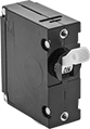 |
1 Pole—Toggle-Switch Style |
Unlike breakers that trip thermally, these breakers have a hydraulic-magnetic trip mechanism, so they aren’t affected by changes in temperature. Instead, these circuit breakers trip when they hydraulically sense consistent low-level overload current, or they trip quickly when the magnetic coil senses a high-current short circuit. Use the threaded holes on the face to install them through panels, enclosure covers, or walls to keep them close to the equipment they protect.
Breakthrough Current @ Voltage—Breakthrough current is the maximum current that the circuit breaker can safely stop in the event of a short circuit.
For Panel Cutout | Mounting Holes | ||||||||||||||||||||||||||||||||||||||||||||||||||||||||||||||||||||||||||||||||||||||||||||||||||
|---|---|---|---|---|---|---|---|---|---|---|---|---|---|---|---|---|---|---|---|---|---|---|---|---|---|---|---|---|---|---|---|---|---|---|---|---|---|---|---|---|---|---|---|---|---|---|---|---|---|---|---|---|---|---|---|---|---|---|---|---|---|---|---|---|---|---|---|---|---|---|---|---|---|---|---|---|---|---|---|---|---|---|---|---|---|---|---|---|---|---|---|---|---|---|---|---|---|---|---|
Current, A | Voltage | Freq., Hz | Breakthrough Current @ Voltage | Temp. Range, ° F | Ht. | Wd. | Dp. Behind Panel | No. of | Thread Size | Mounting Fasteners Included | Wire Connection | Ht. | Wd. | Each | |||||||||||||||||||||||||||||||||||||||||||||||||||||||||||||||||||||||||||||||||||||
1 Pole—Toggle-Switch Style | |||||||||||||||||||||||||||||||||||||||||||||||||||||||||||||||||||||||||||||||||||||||||||||||||||
| 50 | 80V DC 250V AC | 50/60 | 1,500 amp @ 250V AC 5,000 amp @ 80V DC | -40 to 185 | 1.45" | 0.76" | 2.573" | 2 | 6-32 | No | Screw Terminal | 2.5" | 0.75" | 72015K35 | 000000 | ||||||||||||||||||||||||||||||||||||||||||||||||||||||||||||||||||||||||||||||||||||
