


Filter by
Fitting Connection

Maximum Pressure @ Temperature
Maximum Temperature
Valve Type
Valve Function
DFARS Specialty Metals
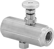
High-Pressure Threaded Precision Flow-Adjustment Valves
316 Stainless Steel Body—Metal-to-Metal Seat
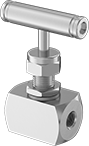 | 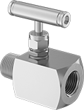 |
Style N | Style P |
316 stainless steel valves are more corrosion resistant than brass and steel valves.
Metal-to-metal seats resist temperature fluctuations.
Flow Coefficient (Cv)—Flow coefficient (Cv) is the amount of water (in gallons per minute) at 60° F that will flow through a fully open valve with a difference of 1 psi between the inlet and the outlet.
Packing Material—Valves with packing have a nut that can be tightened to compress the packing if it leaks.
Style | Pipe Size | Flow Coefficient (Cv) | Max. Pressure @ Temp. | Temp. Range, ° F | Packing Material | Port-to-Port Lg. | For Use With | Valve Type | Each | |||
|---|---|---|---|---|---|---|---|---|---|---|---|---|
BSPP Female × BSPP Female | ||||||||||||
| N | 1/8 | 0.4 | 6,000 psi @ 100° F | -100 to 500 | PTFE | 1 9/16" | Oil, Acetone, Air, Ammonia, Diesel Fuel | Needle | 4999K68 | 000000 | ||
| N | 1/4 | 0.4 | 6,000 psi @ 100° F | -100 to 500 | PTFE | 1 7/8" | Oil, Acetone, Air, Ammonia, Diesel Fuel | Needle | 4999K43 | 00000 | ||
| N | 1/4 | 0.4 | 10,000 psi @ 100° F | -100 to 500 | PTFE | 1 7/8" | Oil, Acetone, Air, Ammonia, Diesel Fuel | Needle | 4999K59 | 00000 | ||
| N | 3/8 | 0.4 | 6,000 psi @ 100° F | -100 to 500 | PTFE | 1 7/8" | Oil, Acetone, Air, Ammonia, Diesel Fuel | Needle | 4999K69 | 00000 | ||
| N | 1/2 | 0.46 | 6,000 psi @ 100° F | -100 to 500 | PTFE | 2 11/16" | Oil, Acetone, Air, Ammonia, Diesel Fuel | Needle | 4999K45 | 00000 | ||
| N | 1/2 | 0.46 | 10,000 psi @ 100° F | -100 to 500 | PTFE | 2 11/16" | Oil, Acetone, Air, Ammonia, Diesel Fuel | Needle | 4999K62 | 00000 | ||
| N | 3/4 | 0.75 | 6,000 psi @ 100° F | -100 to 500 | PTFE | 2 11/16" | Oil, Acetone, Air, Ammonia, Diesel Fuel | Needle | 4999K71 | 00000 | ||
BSPP Male × BSPP Female | ||||||||||||
| P | 1/4 | 0.28 | 6,000 psi @ 100° F | -100 to 500 | PTFE | 1 15/16" | Oil, Acetone, Air, Ammonia, Diesel Fuel | Needle | 4999K72 | 00000 | ||
BSPT Female × BSPT Female | ||||||||||||
| N | 1/8 | 0.4 | 6,000 psi @ 100° F | -100 to 500 | PTFE | 1 9/16" | Oil, Acetone, Air, Ammonia, Diesel Fuel | Needle | 4999K34 | 00000 | ||
| N | 1/2 | 0.46 | 6,000 psi @ 100° F | -100 to 500 | PTFE | 2 11/16" | Oil, Acetone, Air, Ammonia, Diesel Fuel | Needle | 4999K37 | 00000 | ||
BSPT Male × BSPT Female | ||||||||||||
| P | 1/2 | 0.46 | 6,000 psi @ 100° F | -100 to 500 | PTFE | 2 11/16" | Oil, Acetone, Air, Ammonia, Diesel Fuel | Needle | 4999K67 | 00000 | ||
Elbow Air Flow Control Valves
BSPT Male Inlet × Push-to-Connect Female Outlet
 |  | 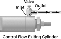 |
Polybutylene Body | Polybutylene Body with Pressure-Release Button | Meter Out |
Flow Rate @ 73 psi, scfm | Flow Rate @ 100 psi, scfm | |||||||||||||
|---|---|---|---|---|---|---|---|---|---|---|---|---|---|---|
Inlet Pipe Size | For Outlet Tube OD, mm | Flow Coefficient (Cv) | Min. | Max. | Min. | Max. | Max. Pressure, psi | Temp. Range, ° F | Flow Adjustment Mechanism | Flow Control Location (ISO Designation) | Each | |||
Polybutylene Body | ||||||||||||||
| 1/8 | 4 | 0.15 | — | — | 0 | 4.8 | 150 | 0 to 175 | Dial | Exiting Cylinder (Meter Out) | 62005K521 | 000000 | ||
| 1/8 | 6 | 0.19 | — | — | 0 | 6.1 | 150 | 0 to 175 | Dial | Exiting Cylinder (Meter Out) | 62005K522 | 00000 | ||
| 1/8 | 8 | 0.19 | — | — | 0 | 6.1 | 150 | 0 to 175 | Dial | Exiting Cylinder (Meter Out) | 62005K523 | 00000 | ||
| 1/4 | 4 | 0.22 | — | — | 0 | 7 | 150 | 0 to 175 | Dial | Exiting Cylinder (Meter Out) | 62005K531 | 00000 | ||
| 1/4 | 6 | 0.33 | — | — | 0 | 10.5 | 150 | 0 to 175 | Dial | Exiting Cylinder (Meter Out) | 62005K532 | 00000 | ||
| 1/4 | 8 | 0.39 | — | — | 0 | 12.5 | 150 | 0 to 175 | Dial | Exiting Cylinder (Meter Out) | 62005K533 | 00000 | ||
| 3/8 | 6 | 0.56 | — | — | 0 | 17.9 | 150 | 0 to 175 | Dial | Exiting Cylinder (Meter Out) | 62005K551 | 00000 | ||
| 3/8 | 8 | 0.67 | — | — | 0 | 21.4 | 150 | 0 to 175 | Dial | Exiting Cylinder (Meter Out) | 62005K552 | 00000 | ||
| 1/2 | 10 | 1.33 | — | — | 0 | 42.5 | 150 | 0 to 175 | Dial | Exiting Cylinder (Meter Out) | 62005K56 | 00000 | ||
Polybutylene Body with Pressure-Release Button | ||||||||||||||
| 1/8 | 6 | 0.2 | 0 | 9.28 | — | — | 145 | 25 to 140 | Dial | Exiting Cylinder (Meter Out) | 62005K171 | 00000 | ||
| 1/8 | 8 | 0.2 | 0 | 9.28 | — | — | 145 | 25 to 140 | Dial | Exiting Cylinder (Meter Out) | 62005K172 | 00000 | ||
| 1/4 | 6 | 0.2 | 0 | 9.28 | — | — | 145 | 25 to 140 | Dial | Exiting Cylinder (Meter Out) | 62005K173 | 00000 | ||
| 1/4 | 8 | 0.2 | 0 | 9.28 | — | — | 145 | 25 to 140 | Dial | Exiting Cylinder (Meter Out) | 62005K174 | 00000 | ||
BSPP Male Inlet × BSPP Female Outlet
 | |
Meter Out |
Flow Rate @ 100 psi | ||||||||||||
|---|---|---|---|---|---|---|---|---|---|---|---|---|
Inlet Pipe Size | Outlet Pipe Size | Flow Coefficient (Cv) | Min. | Max., scfm | Max. Pressure, psi | Temp. Range, ° F | Flow Adjustment Mechanism | Flow Control Location (ISO Designation) | Each | |||
Zinc Alloy Body | ||||||||||||
| 1/8 | 1/8 | 0.34 | Not Rated | 12.6 | 145 | 15 to 140 | Dial | Exiting Cylinder (Meter Out) | 6857K25 | 000000 | ||
| 1/4 | 1/4 | 0.61 | Not Rated | 22.6 | 145 | 15 to 140 | Dial | Exiting Cylinder (Meter Out) | 6857K26 | 00000 | ||
Push-to-Connect Female Inlet × BSPT Male Outlet
 | 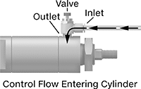 |
Meter In |
Flow Rate @ 100 psi, scfm | ||||||||||||
|---|---|---|---|---|---|---|---|---|---|---|---|---|
For Inlet Tube OD, mm | Outlet Pipe Size | Flow Coefficient (Cv) | Min. | Max. | Max. Pressure, psi | Temp. Range, ° F | Flow Adjustment Mechanism | Flow Control Location (ISO Designation) | Each | |||
Polybutylene Body | ||||||||||||
| 4 | 1/8 | 0.15 | 0 | 4.8 | 150 | 0 to 175 | Dial | Entering Cylinder (Meter In) | 62005K421 | 000000 | ||
| 4 | 1/4 | 0.22 | 0 | 7 | 150 | 0 to 175 | Dial | Entering Cylinder (Meter In) | 62005K431 | 00000 | ||
| 6 | 1/8 | 0.19 | 0 | 6.1 | 150 | 0 to 175 | Dial | Entering Cylinder (Meter In) | 62005K422 | 00000 | ||
| 6 | 1/4 | 0.33 | 0 | 10.5 | 150 | 0 to 175 | Dial | Entering Cylinder (Meter In) | 62005K432 | 00000 | ||
| 6 | 3/8 | 0.56 | 0 | 17.9 | 150 | 0 to 175 | Dial | Entering Cylinder (Meter In) | 62005K451 | 00000 | ||
| 8 | 1/8 | 0.19 | 0 | 6.1 | 150 | 0 to 175 | Dial | Entering Cylinder (Meter In) | 62005K423 | 00000 | ||
| 8 | 1/4 | 0.39 | 0 | 12.5 | 150 | 0 to 175 | Dial | Entering Cylinder (Meter In) | 62005K433 | 00000 | ||
| 8 | 3/8 | 0.67 | 0 | 21.4 | 150 | 0 to 175 | Dial | Entering Cylinder (Meter In) | 62005K452 | 00000 | ||
| 10 | 1/2 | 1.33 | 0 | 42.5 | 150 | 0 to 175 | Dial | Entering Cylinder (Meter In) | 62005K46 | 00000 | ||
Easy-Set Threaded Precision Flow-Adjustment Valves
Brass Body—Straight
 |
Flow Coefficient (Cv)—Flow coefficient (Cv) is the amount of water (in gallons per minute) at 60° F that will flow through a fully open valve with a difference of 1 psi between the inlet and the outlet.
Overall | ||||||||||||||
|---|---|---|---|---|---|---|---|---|---|---|---|---|---|---|
Pipe Size | Flow Coefficient (Cv) | Max. Pressure @ Temp. | Ht. | Lg. | Temp. Range, ° F | Seal Material | Needle Material | End-to-End Lg. | For Use With | Valve Type | Each | |||
BSPP Female × BSPP Female | ||||||||||||||
| 1/4 | 0.51 | 2,000 psi @ 400° F | 2 3/16" | 1 3/4" | -15 to 400 | Fluoroelastomer | Brass | 1 3/4" | Water, Oil, Air, Argon, Helium, Krypton, Neon, Xenon | Needle | 5513N18 | 000000 | ||
| 1/4 | 0.53 | 2,000 psi @ 190° F | 2 3/16" | 2 1/2" | -15 to 200 | Fluoroelastomer | Brass | 2 1/2" | Water, Oil, Air, Argon, Helium, Krypton, Neon, Xenon | Needle | 5513N21 | 00000 | ||
| 3/8 | 0.92 | 2,000 psi @ 400° F | 2 5/8" | 2 1/16" | -15 to 400 | Fluoroelastomer | Brass | 2 1/16" | Water, Oil, Air, Argon, Helium, Krypton, Neon, Xenon | Needle | 5513N19 | 00000 | ||
| 1/2 | 0.93 | 2,000 psi @ 190° F | 3 1/8" | 3 7/16" | -15 to 200 | Fluoroelastomer | Brass | 3 7/16" | Water, Oil, Air, Argon, Helium, Krypton, Neon, Xenon | Needle | 5513N23 | 000000 | ||
BSPT Female × BSPT Female | ||||||||||||||
| 1/8 | 0.25 | 2,000 psi @ 400° F | 1 15/16" | 1 7/16" | -15 to 400 | Fluoroelastomer | Brass | 1 7/16" | Water, Oil, Air, Argon, Helium, Krypton, Neon, Xenon | Needle | 5513N11 | 00000 | ||
| 1/4 | 0.51 | 2,000 psi @ 400° F | 2 3/16" | 1 3/4" | -15 to 400 | Fluoroelastomer | Brass | 1 3/4" | Water, Oil, Air, Argon, Helium, Krypton, Neon, Xenon | Needle | 5513N12 | 00000 | ||
| 3/8 | 0.92 | 2,000 psi @ 400° F | 2 5/8" | 2 1/16" | -15 to 400 | Fluoroelastomer | Brass | 2 1/16" | Water, Oil, Air, Argon, Helium, Krypton, Neon, Xenon | Needle | 5513N13 | 00000 | ||
Steel Body
|
Flow Coefficient (Cv)—Flow coefficient (Cv) is the amount of water (in gallons per minute) at 60° F that will flow through a fully open valve with a difference of 1 psi between the inlet and the outlet.
Overall | ||||||||||||||
|---|---|---|---|---|---|---|---|---|---|---|---|---|---|---|
Pipe Size | Flow Coefficient (Cv) | Max. Pressure @ Temp. | Ht. | Lg. | Temp. Range, ° F | Seal Material | Needle Material | End-to-End Lg. | For Use With | Valve Type | Each | |||
BSPT Female × BSPT Female | ||||||||||||||
| 3/8 | 0.92 | 5,000 psi @ 400° F | 2 5/8" | 2 1/16" | -15 to 400 | Fluoroelastomer | 416 Stainless Steel | 2 1/16" | Water, Oil, Air, Argon, Helium, Krypton, Neon, Xenon | Needle | 5514N12 | 000000 | ||
| 1/2 | 0.93 | 5,000 psi @ 190° F | 3 1/8" | 3 7/16" | -15 to 200 | Fluoroelastomer | 416 Stainless Steel | 3 7/16" | Water, Oil, Air, Argon, Helium, Krypton, Neon, Xenon | Needle | 5514N15 | 000000 | ||
| 3/4 | 1.43 | 5,000 psi @ 190° F | 3 9/16" | 3 3/4" | -15 to 200 | Fluoroelastomer | 416 Stainless Steel | 3 3/4" | Water, Oil, Air, Argon, Helium, Krypton, Neon, Xenon | Needle | 5514N16 | 000000 | ||
Air-Exhaust Flow Control Valves
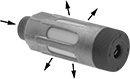 | 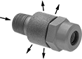 |
Dial Flow Adjustment | Slotted Screw Flow Adjustment |
 |  |
Thumb Screw Flow Adjustment |
Install these valves in the exhaust ports of air directional control valves to control exhaust air speed without needing access to your cylinder. They control flow in one direction as air moves from the inlet to the exhaust port (meter out). Air flows freely in the opposite direction. Valves exhaust to the atmosphere and include a muffler to reduce the exhaust noise.
Flow Coefficient (Cv)—Flow coefficient (Cv) is a measurement that indicates how much airflow can pass through a valve. When selecting between valves with the same port size, choose the valve with the higher flow coefficient to ensure it provides enough airflow to operate your system.
Overall, mm | ||||||||||||
|---|---|---|---|---|---|---|---|---|---|---|---|---|
No. of Flow Ports | Inlet Size | Max. Flow Rate @ Pressure | Flow Coefficient (Cv) | Max. Pressure, psi | Body Material | Hex Size, mm | Dia | Lg. | Each | |||
Threaded Male Inlet | ||||||||||||
Flow-Adjustment Dial | ||||||||||||
| 2 | 1/8 BSPP | 35 scfm @ 100 psi | 1.016 | 145 | Aluminum | — | 16 | 46 | 9164K15 | 000000 | ||
| 2 | 1/4 BSPP | 52.5 scfm @ 100 psi | 1.524 | 145 | Aluminum | — | 19.5 | 63.3 | 9164K16 | 00000 | ||
| 2 | 3/8 BSPP | 59.5 scfm @ 100 psi | 1.728 | 145 | Aluminum | — | 25 | 95.3 | 9164K17 | 00000 | ||
| 2 | 1/2 BSPP | 141.26 scfm @ 100 psi | 2.982 | 145 | Aluminum | — | 28 | 130 | 9164K109 | 00000 | ||
| 2 | 3/4 BSPP | 268.39 scfm @ 100 psi | 5.965 | 145 | Aluminum | — | 38 | 157 | 9164K111 | 00000 | ||
Flow-Adjustment Slotted Screw | ||||||||||||
| 2 | 1/8 BSPP | 19.21 scfm @ 100 psi | 0.52 | 145 | Aluminum | 14 | 15 | 27 | 9164K101 | 00000 | ||
| 2 | 1/4 BSPP | 37 scfm @ 100 psi | 1 | 145 | Aluminum | 17 | 18.2 | 32.1 | 9164K102 | 00000 | ||
| 2 | 3/8 BSPP | 74 scfm @ 100 psi | 2 | 145 | Aluminum | 22 | 25 | 41.1 | 9164K103 | 00000 | ||
| 2 | 1/2 BSPP | 133.2 scfm @ 100 psi | 3.6 | 145 | Aluminum | 24 | 27 | 44.6 | 9164K104 | 00000 | ||
Flow-Adjustment Thumb Screw | ||||||||||||
| 2 | 1/8 BSPT | 10.59 scfm @ 100 psi | 0.201 | 145 | Brass | 10 | 14 | 35.8 | 9164K107 | 00000 | ||
| 2 | 1/4 BSPT | 17.66 scfm @ 100 psi | 0.313 | 145 | Brass | 14 | 18 | 37 | 9164K108 | 00000 | ||
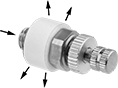
High-Pressure Air Flow Control Valves
BSPP, BSPT, NPT, NPTF Male Inlet × Push-to-Connect Female Outlet
 |  | |
Dial Flow Adjustment | Slotted Screw Flow Adjustment | Meter Out |
NPTF (Dryseal) threads are compatible with NPT threads.
Flow Rate @ 100 psi, scfm | ||||||||||||
|---|---|---|---|---|---|---|---|---|---|---|---|---|
Inlet Pipe Size | For Outlet Tube OD | Flow Coefficient (Cv) | Min. | Max. | Max. Pressure, psi | Temp. Range, ° F | Flow Adjustment Mechanism | Flow Control Location (ISO Designation) | Each | |||
Brass Body | ||||||||||||
| 1/8 | 1/8" | 0.09 | 0 | 5 | 265 | -20 to 175 | Dial | Exiting Cylinder (Meter Out) | 2273K31 | 000000 | ||
| 1/8 | 5/32" | 0.14 | 0 | 7.8 | 265 | -20 to 175 | Slotted Screw | Exiting Cylinder (Meter Out) | 1045K12 | 00000 | ||
| 1/8 | 1/4" | 0.22 | 0 | 12.3 | 265 | -20 to 175 | Dial | Exiting Cylinder (Meter Out) | 2273K33 | 00000 | ||
| 1/8 | 1/4" | 0.22 | 0 | 12.3 | 265 | -20 to 175 | Slotted Screw | Exiting Cylinder (Meter Out) | 1045K13 | 00000 | ||
| 1/4 | 1/4" | 0.27 | 0 | 15.1 | 265 | -20 to 175 | Dial | Exiting Cylinder (Meter Out) | 2273K34 | 00000 | ||
| 1/4 | 1/4" | 0.27 | 0 | 15.1 | 265 | -20 to 175 | Slotted Screw | Exiting Cylinder (Meter Out) | 1045K14 | 00000 | ||
| 1/4 | 3/8" | 0.41 | 0 | 23 | 265 | -20 to 175 | Dial | Exiting Cylinder (Meter Out) | 2273K37 | 00000 | ||
| 1/4 | 3/8" | 0.41 | 0 | 23 | 265 | -20 to 175 | Slotted Screw | Exiting Cylinder (Meter Out) | 1045K17 | 00000 | ||
| 3/8 | 3/8" | 0.42 | 0 | 23.5 | 265 | -20 to 175 | Dial | Exiting Cylinder (Meter Out) | 2273K38 | 00000 | ||
| 3/8 | 3/8" | 0.42 | 0 | 23.5 | 265 | -20 to 175 | Slotted Screw | Exiting Cylinder (Meter Out) | 1045K18 | 00000 | ||
Dual-Control Two-Direction Air Flow Control Valves
BSPP Female Inlet × BSPP Female Outlet
 |  |  |
Meter Out | Meter In |
Flow Rate @ 100 psi | ||||||||||||
|---|---|---|---|---|---|---|---|---|---|---|---|---|
Inlet Pipe Size | Outlet Pipe Size | Flow Coefficient (Cv) | Min. | Max., scfm | Max. Pressure, psi | Temp. Range, ° F | Flow Adjustment Mechanism | Flow Control Location (ISO Designation) | Each | |||
Aluminum Body | ||||||||||||
| 1/8 | 1/8 | 0.18 | Not Rated | 6.8 | 145 | 0 to 140 | Dial | Exiting Cylinder (Meter Out), Entering Cylinder (Meter In) | 8897K12 | 0000000 | ||
Single-Control Two-Direction Air Flow Control Valves
BSPP Female Inlet × BSPP Female Outlet
 | | |
Meter Out | Meter In |
Flow Rate @ 100 psi | ||||||||||||
|---|---|---|---|---|---|---|---|---|---|---|---|---|
Inlet Pipe Size | Outlet Pipe Size | Flow Coefficient (Cv) | Min. | Max., scfm | Max. Pressure, psi | Temp. Range, ° F | Flow Adjustment Mechanism | Flow Control Location (ISO Designation) | Each | |||
Aluminum Body | ||||||||||||
| 1/8 | 1/8 | 0.19 | Not Rated | 7.17 | 145 | -4 to 140 | Dial | Exiting Cylinder (Meter Out), Entering Cylinder (Meter In) | 8642K12 | 0000000 | ||
| 1/4 | 1/4 | 0.35 | Not Rated | 12.95 | 145 | -4 to 140 | Dial | Exiting Cylinder (Meter Out), Entering Cylinder (Meter In) | 8642K13 | 000000 | ||
Elbow Corrosion-Resistant Air Flow Control Valves
BSPT Male Inlet × Push-to-Connect Female Outlet
 | |
Meter Out |
Flow Rate @ 73 psi, scfm | ||||||||||||
|---|---|---|---|---|---|---|---|---|---|---|---|---|
Inlet Pipe Size | For Outlet Tube OD, mm | Flow Coefficient (Cv) | Min. | Max. | Max. Pressure, psi | Temp. Range, ° F | Flow Adjustment Mechanism | Flow Control Location (ISO Designation) | Each | |||
Polybutylene Body with Pressure-Release Button | ||||||||||||
| 1/8 | 6 | 0.07 | 0 | 2.6 | 145 | 25 to 140 | Dial | Exiting Cylinder (Meter Out) | 9066K52 | 000000 | ||
| 1/8 | 8 | 0.07 | 0 | 2.6 | 145 | 25 to 140 | Dial | Exiting Cylinder (Meter Out) | 9066K53 | 00000 | ||
| 1/4 | 8 | 0.07 | 0 | 2.6 | 145 | 25 to 140 | Dial | Exiting Cylinder (Meter Out) | 9066K54 | 00000 | ||
Precision-Adjust Air Flow Control Valves
BSPT Male Inlet × Push-to-Connect Female Outlet
 | |
Meter Out |
Flow Rate @ 73 psi, scfm | ||||||||||||
|---|---|---|---|---|---|---|---|---|---|---|---|---|
Inlet Pipe Size | For Outlet Tube OD, mm | Flow Coefficient (Cv) | Min. | Max. | Max. Pressure, psi | Temp. Range, ° F | Flow Adjustment Mechanism | Flow Control Location (ISO Designation) | Each | |||
Polybutylene Body | ||||||||||||
| 1/8 | 4 | 0.15 | 0 | 7.2 | 145 | 32 to 140 | Dial | Exiting Cylinder (Meter Out) | 4057T11 | 000000 | ||
| 1/8 | 6 | 0.19 | 0 | 9.2 | 145 | 32 to 140 | Dial | Exiting Cylinder (Meter Out) | 4057T12 | 00000 | ||
| 1/8 | 8 | 0.19 | 0 | 9.2 | 145 | 32 to 140 | Dial | Exiting Cylinder (Meter Out) | 4057T13 | 00000 | ||
| 1/4 | 4 | 0.22 | 0 | 11.2 | 145 | 32 to 140 | Dial | Exiting Cylinder (Meter Out) | 4057T14 | 00000 | ||
| 1/4 | 6 | 0.33 | 0 | 15.6 | 145 | 32 to 140 | Dial | Exiting Cylinder (Meter Out) | 4057T15 | 00000 | ||
| 1/4 | 8 | 0.39 | 0 | 18.4 | 145 | 32 to 140 | Dial | Exiting Cylinder (Meter Out) | 4057T16 | 00000 | ||
| 1/4 | 10 | 0.39 | 0 | 18.4 | 145 | 32 to 140 | Dial | Exiting Cylinder (Meter Out) | 4057T17 | 00000 | ||
Push-to-Connect Female Inlet × BSPT Male Outlet
 | |
Meter In |
Flow Rate @ 73 psi, scfm | ||||||||||||
|---|---|---|---|---|---|---|---|---|---|---|---|---|
For Inlet Tube OD, mm | Outlet Pipe Size | Flow Coefficient (Cv) | Min. | Max. | Max. Pressure, psi | Temp. Range, ° F | Flow Adjustment Mechanism | Flow Control Location (ISO Designation) | Each | |||
Polybutylene Body | ||||||||||||
| 4 | 1/8 | 0.15 | 0 | 7.2 | 145 | 32 to 140 | Dial | Entering Cylinder (Meter In) | 4057T18 | 000000 | ||
| 4 | 1/4 | 0.22 | 0 | 11.2 | 145 | 32 to 140 | Dial | Entering Cylinder (Meter In) | 4057T22 | 00000 | ||
| 6 | 1/8 | 0.19 | 0 | 9.2 | 145 | 32 to 140 | Dial | Entering Cylinder (Meter In) | 4057T19 | 00000 | ||
| 6 | 1/4 | 0.33 | 0 | 15.6 | 145 | 32 to 140 | Dial | Entering Cylinder (Meter In) | 4057T23 | 00000 | ||
| 8 | 1/8 | 0.19 | 0 | 9.2 | 145 | 32 to 140 | Dial | Entering Cylinder (Meter In) | 4057T21 | 00000 | ||
| 8 | 1/4 | 0.39 | 0 | 18.4 | 145 | 32 to 140 | Dial | Entering Cylinder (Meter In) | 4057T24 | 00000 | ||
| 10 | 1/4 | 0.39 | 0 | 18.4 | 145 | 32 to 140 | Dial | Entering Cylinder (Meter In) | 4057T25 | 00000 | ||
Threaded Precision Flow-Adjustment Valves
BSPT Female × BSPT Female
 |
Locking Handle—Locking handles have a nut to prevent accidental flow adjustment.
Internal Check Valve—Internal check valves actuate when the pressure changes to stop flow from the controlled direction and allow free flow in the opposite direction. Valves with an internal check valve are often used to control the speed of air cylinders and air-powered motors.
Flow Coefficient (Cv)—Flow coefficient (Cv) is the amount of water (in gallons per minute) at 60° F that will flow through a fully open valve with a difference of 1 psi between the inlet and the outlet.
Pipe Size | Flow Coefficient (Cv) | Max. Pressure @ Temp. | Temp. Range, ° F | End-to-End Lg. | Valve Type | For Use With | Seal Material | Each | |||
|---|---|---|---|---|---|---|---|---|---|---|---|
Brass Body with Locking Knob Handle | |||||||||||
| 1/8 | 0.2 | 2,000 psi @ 400° F | -15 to 400 | 1 1/2" | Needle | Water, Oil, Air, Argon, Helium, Krypton, Neon, Xenon | Fluoroelastomer/PTFE Plastic | 7822K13 | 000000 | ||
| 1/4 | 0.43 | 2,000 psi @ 400° F | -15 to 400 | 2" | Needle | Water, Oil, Air, Argon, Helium, Krypton, Neon, Xenon | Fluoroelastomer/PTFE Plastic | 7822K11 | 00000 | ||
| 3/8 | 0.78 | 2,000 psi @ 400° F | -15 to 400 | 2 1/4" | Needle | Water, Oil, Air, Argon, Helium, Krypton, Neon, Xenon | Fluoroelastomer/PTFE Plastic | 7822K12 | 00000 | ||
Brass Body with Locking Knob Handle and Internal Check Valve | |||||||||||
| 1/4 | 0.54 | 2,000 psi @ 400° F | -15 to 400 | 2 3/8" | Needle | Water, Oil, Air, Argon, Helium, Krypton, Neon, Xenon | Fluoroelastomer/PTFE Plastic | 7822K21 | 00000 | ||
| 3/8 | 0.83 | 2,000 psi @ 400° F | -15 to 400 | 2 3/4" | Needle | Water, Oil, Air, Argon, Helium, Krypton, Neon, Xenon | Fluoroelastomer/PTFE Plastic | 7822K22 | 00000 | ||
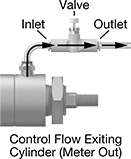
Inline Air Flow Control Valves with Flow Indicator
BSPP Female Inlet × BSPP Female Outlet
 | | |
Meter Out | Meter In |
Flow Rate @ 73 psi, scfm | ||||||||||||
|---|---|---|---|---|---|---|---|---|---|---|---|---|
Inlet Pipe Size | Outlet Pipe Size | Flow Coefficient (Cv) | Min. | Max. | Max. Pressure, psi | Temp. Range, ° F | Flow Adjustment Mechanism | Flow Control Location (ISO Designation) | Each | |||
Aluminum Body with Flow Indicator | ||||||||||||
| 1/4 | 1/4 | 0.82 | 0 | 32.4 | 145 | 25 to 140 | Dial | Exiting Cylinder (Meter Out), Entering Cylinder (Meter In) | 3019N121 | 000000 | ||
| 3/8 | 3/8 | 0.82 | 0 | 32.4 | 145 | 25 to 140 | Dial | Exiting Cylinder (Meter Out), Entering Cylinder (Meter In) | 3019N122 | 00000 | ||
Elbow Air Flow Control Valves with Flow Indicator
BSPT Male Inlet × Push-to-Connect Female Outlet
|  |
Meter Out |
Flow Rate @ 73 psi, scfm | ||||||||||||
|---|---|---|---|---|---|---|---|---|---|---|---|---|
Inlet Pipe Size | For Outlet Tube OD, mm | Flow Coefficient (Cv) | Min. | Max. | Max. Pressure, psi | Temp. Range, ° F | Flow Adjustment Mechanism | Flow Control Location (ISO Designation) | Each | |||
Polybutylene Body with Flow Indicator | ||||||||||||
| 1/8 | 6 | 0.17 | 0 | 5.2 | 145 | 25 to 140 | Dial | Exiting Cylinder (Meter Out) | 2768N25 | 000000 | ||
| 1/4 | 8 | 0.17 | 0 | 5.2 | 145 | 25 to 140 | Dial | Exiting Cylinder (Meter Out) | 2768N26 | 00000 | ||
Air-Operated Air Flow Control Valves with Safety Shut-Off
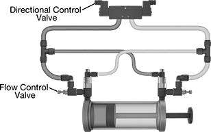 |
Protect air-powered equipment in emergency shut-off situations—when system pressure drops, the air signal stops and these valves automatically close to stop cylinder motion, even at a mid-stroke. They control the speed of air-powered equipment by adjusting the volume of airflow. A pressure-release button allows you to exhaust any trapped air pressure from the system after shut down. Install them in pairs on cylinder exhaust ports, and use tee connectors (not included) to direct exhaust air from the cylinder to the air of the opposite valve, and to connect valves to a directional control valve. The elbow shape allows you to mount them directly to cylinder ports, eliminating additional tubing or piping between the cylinder and valve for better control and consistency than inline valves.
Flow coefficient (Cv) is a measurement that indicates how much airflow can pass through a valve.
Push-to-Connect Female Inlet × BSPP Male Outlet × Push-to-Connect Female Air Pilot
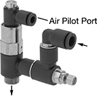 |
Valves with push-to-connect ports are for use with plastic or soft metal tubing. Insert tubing into the port.
One Direction—One direction valves control flow as air exits the cylinder (meter out) and moves from the inlet to the outlet.
Flow Rate @ 87 psi, scfm | ||||||||||||||
|---|---|---|---|---|---|---|---|---|---|---|---|---|---|---|
For Inlet Tube OD, mm | Outlet Pipe Size | For Air Pilot Tube OD, mm | Flow Coefficient (Cv) | Min. | Max. | Max. Pressure, psi | Temp. Range, ° F | Flow Adjustment Mechanism | Flow Control Location (ISO Designation) | Features | Each | |||
Nylon Body—One Direction | ||||||||||||||
| 6 | 1/4 | 4 | Not Rated | 0 | 16.77 | 145 | 25 to 140 | Dial | Exiting Cylinder (Meter Out) | Pressure-Release Button | 2747N114 | 0000000 | ||
| 8 | 1/8 | 4 | Not Rated | 0 | 8.48 | 145 | 25 to 140 | Dial | Exiting Cylinder (Meter Out) | Pressure-Release Button | 2747N115 | 000000 | ||
| 8 | 3/8 | 4 | Not Rated | 0 | 30.9 | 145 | 25 to 140 | Dial | Exiting Cylinder (Meter Out) | Pressure-Release Button | 2747N116 | 000000 | ||
| 10 | 3/8 | 4 | Not Rated | 0 | 33.2 | 145 | 25 to 140 | Dial | Exiting Cylinder (Meter Out) | Pressure-Release Button | 2747N117 | 000000 | ||
