


About Shaft Couplings
More
About Linear Bearings
More
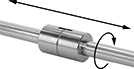
Keyless Locking Shaft Couplings for Overhung Loads
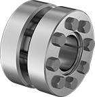
Support the weight of a motor and transfer torque to another shaft at the same time with these couplings. Often used to hang motors from conveyor belts and other driven equipment, or to connect long sections of shafts, these couplings eliminate the need for support brackets. Use a torque arm to prevent hanging motors from spinning.
The clamping screws on the coupling face squeeze two outer collars against an inner ring, pressing it tight against shafts to lock them together. This ring-locking mechanism leaves no room for backlash, meaning that all of the turning force created by the motor is passed on to the second shaft. These couplings grip shafts of any shape, so you can install them onto existing keyways and splines without using a key.
To install these couplings, use a torque wrench to tighten each screw to the fastener tightening torque listed for each coupling size. To remove, gradually loosen each screw in sequence until you can slide the coupling on the shaft. Warning: Do not remove any clamping screws from the coupling until the outer collars are separated from the inner ring. The ring is under tension, and a sudden release of the collars can cause serious injury.
Overhung load capacity is the amount of downward force that a coupling can withstand from a motor or other object that it is supporting. To calculate the overhung load, measure the distance from the center of the coupling to the center of gravity of the motor. Multiply that distance by the combined weight of the motor and the portion of the shaft between the coupling and the motor. Do not exceed the overhung load capacity for a coupling.
| For Shaft Dia. | Overall Lg. | OD | Max. Speed, rpm | Max. Torque, in.-lbs. | Fastener Tightening Torque, in.-lbs. | Overhung Load Cap., in.-lbs. | For Motion Type | Each | |
Steel | |||||||||
|---|---|---|---|---|---|---|---|---|---|
| 1 1/4" | 1 7/8" | 3" | 10,000 | 8,435 | 104 | 2,105 | Forward/Reverse, Start/Stop, Continuous | 0000000 | 0000000 |
| 1 3/8" | 1 7/8" | 3" | 10,000 | 9,285 | 104 | 2,320 | Forward/Reverse, Start/Stop, Continuous | 0000000 | 000000 |
| 1 1/2" | 2 3/16" | 3 3/4" | 8,000 | 17,160 | 264 | 4,290 | Forward/Reverse, Start/Stop, Continuous | 0000000 | 000000 |
| 1 3/4" | 2 3/16" | 3 3/4" | 8,000 | 20,025 | 264 | 5,005 | Forward/Reverse, Start/Stop, Continuous | 0000000 | 000000 |
| 2" | 2 11/16" | 4 7/16" | 7,700 | 32,685 | 264 | 8,170 | Forward/Reverse, Start/Stop, Continuous | 0000000 | 000000 |
| 2 1/4" | 3 1/16" | 4 3/4" | 7,500 | 44,135 | 264 | 11,030 | Forward/Reverse, Start/Stop, Continuous | 0000000 | 000000 |
| 2 1/2" | 3 1/16" | 4 3/4" | 7,500 | 49,040 | 264 | 12,260 | Forward/Reverse, Start/Stop, Continuous | 0000000 | 000000 |
Splined Flexible Shaft Couplings

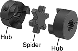
For use with splined shafts, which are commonly found in gearboxes and pumps, these couplings are capable of transmitting more torque than couplings for round and keyed shafts. They have a spider-shaped cushion between two hubs to reduce shock and handle minor shaft misalignment.
A complete coupling consists of two hubs and one spider (each component sold separately). Hubs fasten onto your shafts without damaging them. Tighten the clamping screws to secure.
Buna-N spiders provide good vibration damping and chemical resistance. Hytrel spiders provide fair vibration damping and excellent chemical resistance. Polyurethane spiders provide fair vibration damping and good chemical resistance.
Dia. | ||
|---|---|---|
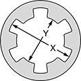
| SAE Spline Size | (X) | (Y) |
| A | 5/8" | 0.509" |
| B | 7/8" | 0.754" |
| B-B | 1" | 0.877" |
| C | 1 1/4" | 1.087" |
| D | 1 3/4" | 1.506" |
| E | 1 3/4" | 1.506" |
Buna-N Rubber Spiders | ||||||||||||||
|---|---|---|---|---|---|---|---|---|---|---|---|---|---|---|
Iron Hubs | Misalignment Capability | |||||||||||||
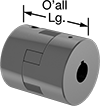
| O'all Lg. | OD | Pitch | Pressure Angle | For Motion Type | Choose an SAE Spline Size | Each | Max. Speed, rpm | Max. Torque, in.-lbs. | Parallel | Angular | Temp. Range, °F | Each | ||
| 2 3/16" | 2 7/64" | 0.5" | 30° | Forward/Reverse, Start/Stop, Continuous | 000000 | 000000 | 9,000 | 140 | 0.015" | 1° | -40° to 212° | 0000000 | 000000 | |
| 2 9/16" | 2 7/64" | 0.5" | 30° | Forward/Reverse, Start/Stop, Continuous | 000000 | 00000 | 9,000 | 140 | 0.015" | 1° | -40° to 212° | 0000000 | 00000 | |
| 2 7/8" | 2 17/32" | 0.5" | 30° | Forward/Reverse, Start/Stop, Continuous | 000000 | 00000 | 7,000 | 315 | 0.015" | 1° | -40° to 212° | 0000000 | 00000 | |
| 3 1/2" | 2 17/32" | 0.5" | 30° | Forward/Reverse, Start/Stop, Continuous | 000000 | 00000 | 7,000 | 315 | 0.015" | 1° | -40° to 212° | 0000000 | 00000 | |
| 4 1/4" | 3 21/64" | 0.5" | 30° | Forward/Reverse, Start/Stop, Continuous | 000000 | 00000 | 5,000 | 790 | 0.015" | 1° | -40° to 212° | 0000000 | 00000 | |
| 4 1/2" | 3 3/4" | 0.5" | 30° | Forward/Reverse, Start/Stop, Continuous | 000000 | 000000 | 5,000 | 1,240 | 0.015" | 1° | -40° to 212° | 0000000 | 00000 | |
Hytrel Rubber Spiders | ||||||||||||||
|---|---|---|---|---|---|---|---|---|---|---|---|---|---|---|
Iron Hubs | Misalignment Capability | |||||||||||||
| O'all Lg. | OD | Pitch | Pressure Angle | For Motion Type | Choose an SAE Spline Size | Each | Max. Speed, rpm | Max. Torque, in.-lbs. | Parallel | Angular | Temp. Range, °F | Each | ||
| 2 3/16" | 2 7/64" | 0.5" | 30° | Forward/Reverse, Start/Stop, Continuous | 000000 | 000000 | 3,600 | 400 | 0.015" | 0.5° | -55° to 245° | 0000000 | 000000 | |
| 2 9/16" | 2 7/64" | 0.5" | 30° | Forward/Reverse, Start/Stop, Continuous | 000000 | 00000 | 3,600 | 400 | 0.015" | 0.5° | -55° to 245° | 0000000 | 00000 | |
| 2 7/8" | 2 17/32" | 0.5" | 30° | Forward/Reverse, Start/Stop, Continuous | 000000 | 00000 | 3,600 | 790 | 0.015" | 0.5° | -55° to 245° | 0000000 | 000000 | |
| 3 1/2" | 2 17/32" | 0.5" | 30° | Forward/Reverse, Start/Stop, Continuous | 000000 | 00000 | 3,600 | 790 | 0.015" | 0.5° | -55° to 245° | 0000000 | 000000 | |
| 4 1/4" | 3 21/64" | 0.5" | 30° | Forward/Reverse, Start/Stop, Continuous | 000000 | 00000 | 3,600 | 2,265 | 0.015" | 0.5° | -55° to 245° | 0000000 | 000000 | |
| 4 1/2" | 3 3/4" | 0.5" | 30° | Forward/Reverse, Start/Stop, Continuous | 000000 | 000000 | 3,600 | 3,705 | 0.015" | 0.5° | -55° to 245° | 0000000 | 000000 | |
Polyurethane Spiders | ||||||||||||||
|---|---|---|---|---|---|---|---|---|---|---|---|---|---|---|
Iron Hubs | Misalignment Capability | |||||||||||||
| O'all Lg. | OD | Pitch | Pressure Angle | For Motion Type | Choose an SAE Spline Size | Each | Max. Speed, rpm | Max. Torque, in.-lbs. | Parallel | Angular | Temp. Range, °F | Each | ||
| 2 3/16" | 2 7/64" | 0.5" | 30° | Forward/Reverse, Start/Stop, Continuous | 000000 | 000000 | 3,600 | 210 | 0.015" | 1° | -30° to 160° | 0000000 | 000000 | |
| 2 9/16" | 2 7/64" | 0.5" | 30° | Forward/Reverse, Start/Stop, Continuous | 000000 | 00000 | 3,600 | 210 | 0.015" | 1° | -30° to 160° | 0000000 | 00000 | |
| 2 7/8" | 2 17/32" | 0.5" | 30° | Forward/Reverse, Start/Stop, Continuous | 000000 | 00000 | 3,600 | 475 | 0.015" | 1° | -30° to 160° | 0000000 | 00000 | |
| 3 1/2" | 2 17/32" | 0.5" | 30° | Forward/Reverse, Start/Stop, Continuous | 000000 | 00000 | 3,600 | 475 | 0.015" | 1° | -30° to 160° | 0000000 | 00000 | |
| 4 1/4" | 3 21/64" | 0.5" | 30° | Forward/Reverse, Start/Stop, Continuous | 000000 | 00000 | 3,600 | 1,185 | 0.015" | 1° | -30° to 160° | 0000000 | 000000 | |
| 4 1/2" | 3 3/4" | 0.5" | 30° | Forward/Reverse, Start/Stop, Continuous | 000000 | 000000 | 3,600 | 1,860 | 0.015" | 1° | -30° to 160° | 0000000 | 000000 | |
Splined-to-Keyed Flexible Shaft Couplings
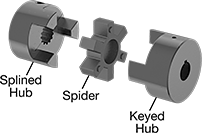
Connect splined shafts to keyed shafts. These couplings are commonly used to connect hydraulic pumps, compressors, and other heavy duty equipment, which often have splined shafts, to electric motors and other components that often have keyed shafts. They have a splined hub on one side and a keyed hub on the other. A spider cushion in the middle damps vibration, absorbs shock loads, and adjusts for misalignment. Because the hubs interlock with the spider, these couplings will continue to work even if the spider breaks or wears away. This fail-safe design gives you time to shut down your power source before damage occurs to other components. Lubrication is not required.
A complete coupling consists of two hubs and one spider. All components are sold separately.
Buna-N spiders are best for high-speed systems and jobs with frequent starting, stopping, and reversing. The most commonly used spider material, Buna-N absorbs vibration better than other materials but cannot handle as much torque. It won't break down when exposed to oil and chemicals.
Use polyurethane spiders for high-torque, continuous-motion applications where vibration is a concern. They absorb vibration better than Hytrel spiders but are not as resistant to oil and chemicals. They're not for use in applications with frequent starting, stopping, and reversing.
Hytrel spiders handle the highest torque of any of our spiders and have the best resistance to oil and chemicals. However, they don't compensate for as much misalignment and are not recommended for applications with frequent starting, stopping, and reversing.
![]() For technical drawings and 3-D models, click on a part number.
For technical drawings and 3-D models, click on a part number.
Dia. | ||
|---|---|---|
| SAE Spline Size | (X) | (Y) |
| A | 5/8" | 0.509" |
| B | 7/8" | 0.754" |
| B-B | 1" | 0.877" |
| C | 1 1/4" | 1.087" |
| D | 1 3/4" | 1.506" |
| E | 1 3/4" | 1.506" |
Buna-N Rubber Spiders | ||||||||||||||||
|---|---|---|---|---|---|---|---|---|---|---|---|---|---|---|---|---|
Splined Iron Hubs | Keyed Iron Hubs | Misalignment Capability | ||||||||||||||
| O'all Lg. | OD | Pitch | Pressure Angle | Choose an SAE Spline Size | Each | For Shaft Dia. | Each | Max. Speed, rpm | Max. Torque, in.-lbs. | Parallel | Angular | Temp. Range, °F | Each | |||
| 2 3/16" | 2 7/64" | 0.5" | 30° | 00000000 | 000000 | 00000000 | 000000 | 9,000 | 140 | 0.015" | 1° | -40° to 212° | 0000000 | 000000 | ||
| 2 7/8" | 2 17/32" | 0.5" | 30° | 00000000 | 00000 | 00000000 | 00000 | 7,000 | 315 | 0.015" | 1° | -40° to 212° | 0000000 | 00000 | ||
| 4 1/2" | 3 3/4" | 0.5" | 30° | 00000000 | 000000 | 00000000 | 00000 | 5,000 | 1,240 | 0.015" | 1° | -40° to 212° | 0000000 | 00000 | ||
Polyurethane Spiders | ||||||||||||||||
|---|---|---|---|---|---|---|---|---|---|---|---|---|---|---|---|---|
Splined Iron Hubs | Keyed Iron Hubs | Misalignment Capability | ||||||||||||||
| O'all Lg. | OD | Pitch | Pressure Angle | Choose an SAE Spline Size | Each | For Shaft Dia. | Each | Max. Speed, rpm | Max. Torque, in.-lbs. | Parallel | Angular | Temp. Range, °F | Each | |||
| 2 3/16" | 2 7/64" | 0.5" | 30° | 00000000 | 000000 | 00000000 | 000000 | 3,600 | 210 | 0.015" | 1° | -30° to 160° | 0000000 | 000000 | ||
| 2 7/8" | 2 17/32" | 0.5" | 30° | 00000000 | 00000 | 00000000 | 00000 | 3,600 | 475 | 0.015" | 1° | -30° to 160° | 0000000 | 00000 | ||
| 4 1/2" | 3 3/4" | 0.5" | 30° | 00000000 | 000000 | 00000000 | 00000 | 3,600 | 1,860 | 0.015" | 1° | -30° to 160° | 0000000 | 000000 | ||
Hytrel Rubber Spiders | ||||||||||||||||
|---|---|---|---|---|---|---|---|---|---|---|---|---|---|---|---|---|
Splined Iron Hubs | Keyed Iron Hubs | Misalignment Capability | ||||||||||||||
| O'all Lg. | OD | Pitch | Pressure Angle | Choose an SAE Spline Size | Each | For Shaft Dia. | Each | Max. Speed, rpm | Max. Torque, in.-lbs. | Parallel | Angular | Temp. Range, °F | Each | |||
| 2 3/16" | 2 7/64" | 0.5" | 30° | 00000000 | 000000 | 00000000 | 000000 | 3,600 | 400 | 0.015" | 0.5° | -55° to 245° | 0000000 | 000000 | ||
| 2 7/8" | 2 17/32" | 0.5" | 30° | 00000000 | 00000 | 00000000 | 00000 | 3,600 | 790 | 0.015" | 0.5° | -55° to 245° | 0000000 | 000000 | ||
| 4 1/2" | 3 3/4" | 0.5" | 30° | 00000000 | 000000 | 00000000 | 00000 | 3,600 | 3,705 | 0.015" | 0.5° | -55° to 245° | 0000000 | 000000 | ||
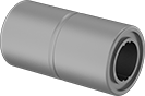
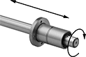
Linear Bearings for Ball Splines

Combine these bearings with a ball spline to create a compact linear and rotary motion system for applications with fast, complex movements, such as robotics. These bearings move smoothly and precisely even at high speeds along ball splines while grooves on the ball spline transmit rotary power. Clip a retaining ring into the groove on these bearings to position them in your system. Use the keyway and included machine key for attaching your load.
Stainless steel bearings are more corrosion resistant than steel bearings.
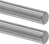
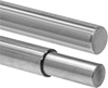
Splines are alloy steel for high strength and wear resistance. They're hardened only on the outside, so they stand up to repeated motion while keeping their center soft enough to absorb stress from shifting loads. Those with a step-down end have a shoulder near the end to stop gears, sprockets, and bearings.
Groove | Keyway | ||||||||||||||||
|---|---|---|---|---|---|---|---|---|---|---|---|---|---|---|---|---|---|
| For Spline Dia., mm | For No. of Splines | Overall Lg., mm | OD, mm | Dynamic Load Capacity, lbs. | Static Load Capacity, lbs. | Max. Dynamic Torque, in.-lbs. | Max. Static Torque, in.-lbs. | Max. Temp., °F | With Retaining Ring Grooves | Wd., mm | Dia., mm | Includes | Lg., mm | Wd., mm | Dp., mm | Each | |
| 6 | 4 | 25 | 14 | 270 | 510 | 13 | 21 | 176° | Yes | 1.3 | 13.3 | Machine Key | 10.5 | 2.5 | 1.2 | 00000000 | 000000 |
| 8 | 4 | 25 | 16 | 325 | 645 | 18 | 32 | 176° | Yes | 1.3 | 15.3 | Machine Key | 10.5 | 2.5 | 1.2 | 00000000 | 00000 |
| 10 | 4 | 33 | 21 | 610 | 1,100 | 38 | 72 | 176° | Yes | 1.7 | 20 | Machine Key | 13 | 3 | 1.5 | 00000000 | 00000 |
| 13 | 4 | 36 | 24 | 600 | 1,050 | 185 | 346 | 176° | Yes | 1.3 | 22.7 | Machine Key | 15 | 3 | 1.5 | 00000000 | 00000 |
| 16 | 4 | 50 | 31 | 1,350 | 2,500 | 531 | 973 | 176° | Yes | 1.6 | 29.4 | Machine Key | 17.5 | 3.5 | 2 | 00000000 | 00000 |
| 18.2 | 4 | 60 | 32 | 1,750 | 2,500 | 734 | 1,177 | 176° | Yes | 3.1 | 30.2 | Machine Key | 26 | 4 | 2.5 | 00000000 | 000000 |
| 25 | 4 | 71 | 42 | 2,850 | 5,250 | 1,672 | 3,062 | 176° | Yes | 2.5 | 39.5 | Machine Key | 36 | 4 | 2.5 | 00000000 | 000000 |
| 28 | 4 | 80 | 45 | 4,150 | 5,200 | 2,557 | 3,646 | 176° | Yes | 4.15 | 42.6 | Machine Key | 41 | 7 | 4 | 00000000 | 000000 |
| 30 | 4 | 80 | 47 | 4,150 | 5,200 | 2,716 | 3,885 | 176° | Yes | 3 | 44 | Machine Key | 42 | 4 | 2.5 | 00000000 | 000000 |
| 40 | 4 | 100 | 64 | 6,900 | 8,400 | 5,964 | 8,266 | 176° | Yes | 4 | 60 | Machine Key | 52 | 6 | 3.5 | 00000000 | 000000 |
Groove | Keyway | ||||||||||||||||
|---|---|---|---|---|---|---|---|---|---|---|---|---|---|---|---|---|---|
| For Spline Dia., mm | For No. of Splines | Overall Lg., mm | OD, mm | Dynamic Load Capacity, lbs. | Static Load Capacity, lbs. | Max. Dynamic Torque, in.-lbs. | Max. Static Torque, in.-lbs. | Max. Temp., °F | With Retaining Ring Grooves | Wd., mm | Dia., mm | Includes | Lg., mm | Wd., mm | Dp., mm | Each | |
| 6 | 4 | 25 | 14 | 270 | 510 | 13 | 21 | 176° | Yes | 0.6 | 13.4 | Machine Key | 10.5 | 2.5 | 1.2 | 00000000 | 0000000 |
| 13 | 4 | 36 | 24 | 600 | 1,050 | 185 | 346 | 176° | Yes | 1.3 | 22.7 | Machine Key | 15 | 3 | 1.5 | 00000000 | 000000 |

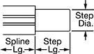
Step | |||||||||
|---|---|---|---|---|---|---|---|---|---|
| Dia., mm | No. of Splines | Lg., mm | Spline Lg., mm | Root Dia., mm | Dia., mm | Lg., mm | Material | Each | |
Splined on Both Ends | |||||||||
| 6 | 4 | 150 | 150 | 5.3 | __ | __ | 52100 Alloy Steel | 00000000 | 0000000 |
| 6 | 4 | 200 | 200 | 5.3 | __ | __ | 52100 Alloy Steel | 000000000 | 000000 |
| 6 | 4 | 300 | 300 | 5.3 | __ | __ | 52100 Alloy Steel | 000000000 | 000000 |
| 8 | 4 | 150 | 150 | 7.2 | __ | __ | 52100 Alloy Steel | 00000000 | 000000 |
| 8 | 4 | 200 | 200 | 7.2 | __ | __ | 52100 Alloy Steel | 000000000 | 000000 |
| 10 | 4 | 200 | 200 | 9 | __ | __ | 52100 Alloy Steel | 00000000 | 000000 |
| 10 | 4 | 300 | 300 | 9 | __ | __ | 52100 Alloy Steel | 000000000 | 000000 |
| 10 | 4 | 600 | 600 | 9 | __ | __ | 52100 Alloy Steel | 000000000 | 000000 |
| 13 | 4 | 200 | 200 | 11.7 | __ | __ | 52100 Alloy Steel | 000000000 | 00000 |
| 13 | 4 | 500 | 500 | 11.7 | __ | __ | 52100 Alloy Steel | 000000000 | 000000 |
| 13 | 4 | 700 | 700 | 11.7 | __ | __ | 52100 Alloy Steel | 000000000 | 000000 |
| 16 | 4 | 200 | 200 | 14.2 | __ | __ | 52100 Alloy Steel | 000000000 | 000000 |
| 16 | 4 | 700 | 700 | 14.2 | __ | __ | 52100 Alloy Steel | 000000000 | 000000 |
| 25 | 4 | 200 | 200 | 22.4 | __ | __ | 52100 Alloy Steel | 000000000 | 000000 |
| 25 | 4 | 500 | 500 | 22.4 | __ | __ | 52100 Alloy Steel | 000000000 | 000000 |
| 30 | 4 | 300 | 300 | 26.8 | __ | __ | 52100 Alloy Steel | 000000000 | 000000 |
| 30 | 4 | 1,000 | 1,000 | 26.8 | __ | __ | 52100 Alloy Steel | 000000000 | 000000 |
| 30 | 4 | 2,000 | 2,000 | 26.8 | __ | __ | 52100 Alloy Steel | 000000000 | 00000000 |
| 40 | 4 | 400 | 400 | 35.5 | __ | __ | 52100 Alloy Steel | 000000000 | 000000 |
| 40 | 4 | 700 | 700 | 35.5 | __ | __ | 52100 Alloy Steel | 000000000 | 000000 |
Splined End × Step-Down End | |||||||||
| 18.2 | 4 | 350 | 200 | 16.4 | 15 | 150 | 52100 Alloy Steel | 00000000 | 000000 |
| 28 | 4 | 450 | 300 | 24.8 | 25 | 150 | 52100 Alloy Steel | 00000000 | 000000 |
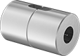
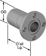
Mounted Linear Bearings for Ball Splines
A flange with mounting holes makes it easy to attach a load to these bearings. Create a compact linear and rotary motion system for robots and other applications requiring complex, fast movements, by combining them with ball splines. These bearings move smoothly and precisely even at high speeds along ball splines while grooves on the ball spline transmit rotary power. Clip a retaining ring (not included) into the groove on these bearings to position them in your system.
Splines are alloy steel for high strength and wear resistance. They're hardened only on the outside, so they stand up to repeated motion while keeping their center soft enough to absorb stress from shifting loads. Those with a step-down end have a shoulder near the end to stop gears, sprockets, and bearings.
Groove | ||||||||||||||||
|---|---|---|---|---|---|---|---|---|---|---|---|---|---|---|---|---|
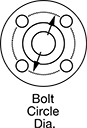
| For Spline Dia., mm | For No. of Splines | Overall Lg., mm | Flange OD, mm | Bolt Circle Dia., mm | OD, mm | Dynamic Load Capacity, lbs. | Static Load Capacity, lbs. | Max. Dynamic Torque, in.-lbs. | Max. Static Torque, in.-lbs. | Max. Temperature, ° F | With Retaining Ring Grooves | Wd., mm | Dia., mm | Number of Mounting Holes | Each | |
| 6 | 4 | 25 | 30 | 22 | 14 | 270 | 510 | 13 | 21 | 176° | Yes | 1.25 | 13.7 | 4 | 00000000 | 000000 |
| 8 | 4 | 25 | 32 | 24 | 16 | 325 | 645 | 18 | 32 | 176° | Yes | 1.25 | 15.6 | 4 | 00000000 | 00000 |
| 10 | 4 | 33 | 42 | 32 | 21 | 610 | 1,100 | 38 | 72 | 176° | Yes | 1.65 | 20.5 | 4 | 00000000 | 000000 |
| 13 | 4 | 36 | 43 | 33 | 24 | 600 | 1,050 | 185 | 346 | 176° | Yes | 1.3 | 22.7 | 4 | 000000000 | 00000 |
| 16 | 4 | 50 | 50 | 40 | 31 | 1,350 | 2,500 | 531 | 973 | 176° | Yes | 1.6 | 29.4 | 4 | 000000000 | 000000 |
| 18.2 | 4 | 60 | 51 | 40 | 32 | 1,750 | 2,500 | 734 | 1,177 | 176° | Yes | 3 | 31.3 | 4 | 00000000 | 000000 |
| 20 | 4 | 63 | 58 | 45 | 35 | 2,000 | 3,650 | 929 | 1,717 | 176° | Yes | 2 | 33 | 4 | 000000000 | 000000 |
| 23 | 4 | 70 | 60 | 47 | 37 | 2,750 | 3,600 | 1,433 | 2,115 | 176° | Yes | 3.5 | 36.1 | 4 | 00000000 | 000000 |
| 25 | 4 | 71 | 65 | 52 | 42 | 2,850 | 5,250 | 1,672 | 3,062 | 176° | Yes | 2.5 | 39.5 | 4 | 000000000 | 000000 |
| 28 | 4 | 80 | 70 | 54 | 45 | 4,150 | 5,200 | 2,557 | 3,646 | 176° | Yes | 4 | 43.9 | 4 | 00000000 | 000000 |
| 30 | 4 | 80 | 75 | 60 | 47 | 4,150 | 5,200 | 2,716 | 3,885 | 176° | Yes | 3 | 44 | 4 | 000000000 | 000000 |
| 37.4 | 4 | 100 | 90 | 72 | 60 | 6,900 | 8,400 | 5,637 | 7,806 | 176° | Yes | 5 | 58.6 | 4 | 00000000 | 000000 |
| 40 | 4 | 100 | 100 | 82 | 64 | 6,900 | 8,400 | 5,964 | 8,266 | 176° | Yes | 4 | 60 | 4 | 000000000 | 000000 |
Step | |||||||||
|---|---|---|---|---|---|---|---|---|---|
| Dia., mm | No. of Splines | Lg., mm | Spline Lg., mm | Root Dia., mm | Dia., mm | Lg., mm | Material | Each | |
Splined on Both Ends | |||||||||
| 6 | 4 | 150 | 150 | 5.3 | __ | __ | 52100 Alloy Steel | 00000000 | 0000000 |
| 6 | 4 | 200 | 200 | 5.3 | __ | __ | 52100 Alloy Steel | 000000000 | 000000 |
| 6 | 4 | 300 | 300 | 5.3 | __ | __ | 52100 Alloy Steel | 000000000 | 000000 |
| 8 | 4 | 150 | 150 | 7.2 | __ | __ | 52100 Alloy Steel | 00000000 | 000000 |
| 8 | 4 | 200 | 200 | 7.2 | __ | __ | 52100 Alloy Steel | 000000000 | 000000 |
| 10 | 4 | 200 | 200 | 9 | __ | __ | 52100 Alloy Steel | 00000000 | 000000 |
| 10 | 4 | 300 | 300 | 9 | __ | __ | 52100 Alloy Steel | 000000000 | 000000 |
| 10 | 4 | 600 | 600 | 9 | __ | __ | 52100 Alloy Steel | 000000000 | 000000 |
| 13 | 4 | 200 | 200 | 11.7 | __ | __ | 52100 Alloy Steel | 000000000 | 00000 |
| 13 | 4 | 500 | 500 | 11.7 | __ | __ | 52100 Alloy Steel | 000000000 | 000000 |
| 13 | 4 | 700 | 700 | 11.7 | __ | __ | 52100 Alloy Steel | 000000000 | 000000 |
| 16 | 4 | 200 | 200 | 14.2 | __ | __ | 52100 Alloy Steel | 000000000 | 000000 |
| 16 | 4 | 700 | 700 | 14.2 | __ | __ | 52100 Alloy Steel | 000000000 | 000000 |
| 20 | 4 | 200 | 200 | 17.9 | __ | __ | 52100 Alloy Steel | 000000000 | 000000 |
| 20 | 4 | 2,000 | 2,000 | 17.9 | __ | __ | 52100 Alloy Steel | 000000000 | 000000 |
| 25 | 4 | 200 | 200 | 22.4 | __ | __ | 52100 Alloy Steel | 000000000 | 000000 |
| 25 | 4 | 500 | 500 | 22.4 | __ | __ | 52100 Alloy Steel | 000000000 | 000000 |
| 30 | 4 | 300 | 300 | 26.8 | __ | __ | 52100 Alloy Steel | 000000000 | 000000 |
| 30 | 4 | 1,000 | 1,000 | 26.8 | __ | __ | 52100 Alloy Steel | 000000000 | 000000 |
| 30 | 4 | 2,000 | 2,000 | 26.8 | __ | __ | 52100 Alloy Steel | 000000000 | 00000000 |
| 40 | 4 | 400 | 400 | 35.5 | __ | __ | 52100 Alloy Steel | 000000000 | 000000 |
| 40 | 4 | 700 | 700 | 35.5 | __ | __ | 52100 Alloy Steel | 000000000 | 000000 |
Splined End × Step-Down End | |||||||||
| 18.2 | 4 | 350 | 200 | 16.4 | 15 | 150 | 52100 Alloy Steel | 00000000 | 000000 |
| 23 | 4 | 350 | 200 | 20.6 | 20 | 150 | 52100 Alloy Steel | 00000000 | 000000 |
| 28 | 4 | 450 | 300 | 24.8 | 25 | 150 | 52100 Alloy Steel | 00000000 | 000000 |
| 37.4 | 4 | 550 | 400 | 33.1 | 30 | 150 | 52100 Alloy Steel | 00000000 | 000000 |