


Filter by
System of Measurement
Thread Size

Threaded Insert Type

Maximum Push Force

Retracted Length

Rod Diameter

Maximum Pull Force
Body Length
Shank Thread Size
Actuation Type
Key-Locking Insert Wall Type
DFARS Specialty Metals
Export Control Classification Number (ECCN)
Hydraulic Cylinders
 |  |  |
Clevis Brackets with Clevis Pin | Front/Rear Flange | Clevis Rod Ends |
 |  |
Clevis Pin | Hydraulic Cylinder |
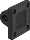 |  |
Pivot Bracket | NFPA and JIC Mounting Pattern |
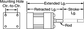
Rod | O'all | Mounting Hole | Inlet/Outlet Connection | ||||||||||||||||||||||||||||||||||||||||||||||||||||||||||||||||||||||||||||||||||||||||||||||||
|---|---|---|---|---|---|---|---|---|---|---|---|---|---|---|---|---|---|---|---|---|---|---|---|---|---|---|---|---|---|---|---|---|---|---|---|---|---|---|---|---|---|---|---|---|---|---|---|---|---|---|---|---|---|---|---|---|---|---|---|---|---|---|---|---|---|---|---|---|---|---|---|---|---|---|---|---|---|---|---|---|---|---|---|---|---|---|---|---|---|---|---|---|---|---|---|---|---|---|---|
Stroke Lg. | Body Lg. | Max. Push Force, lbf | Max. Pull Force, lbf | Retracted Lg. | Extended Lg. | Thread Size | Dia. | Wd. | Ht. | Ctr.-to-Ctr. | Thread Size | Pipe Size | Dash Size | Thread Type | Body Material | Max. Pressure, psi | Cylinder Cushion Type | Each | |||||||||||||||||||||||||||||||||||||||||||||||||||||||||||||||||||||||||||||||||
NFPA/JIC Heavy Duty Mounting Pattern | |||||||||||||||||||||||||||||||||||||||||||||||||||||||||||||||||||||||||||||||||||||||||||||||||||
4" Diameter Bore | |||||||||||||||||||||||||||||||||||||||||||||||||||||||||||||||||||||||||||||||||||||||||||||||||||
| 1" | 7 5/8" | 31,420 | 25,400 | 10 5/8" | 11 5/8" | 1 1/4"-12 | 1 3/4" | 5" | 5" | 3 13/16" | 5/8"-16 | 3/4 | 12 | NPT | Steel | 2,500 | None | 62205K191 | 000000000 | ||||||||||||||||||||||||||||||||||||||||||||||||||||||||||||||||||||||||||||||||
| 2" | 8 5/8" | 31,420 | 25,400 | 11 5/8" | 13 5/8" | 1 1/4"-12 | 1 3/4" | 5" | 5" | 3 13/16" | 5/8"-16 | 3/4 | 12 | NPT | Steel | 2,500 | None | 62205K192 | 00000000 | ||||||||||||||||||||||||||||||||||||||||||||||||||||||||||||||||||||||||||||||||
| 3" | 9 5/8" | 31,420 | 25,400 | 12 5/8" | 15 5/8" | 1 1/4"-12 | 1 3/4" | 5" | 5" | 3 13/16" | 5/8"-16 | 3/4 | 12 | NPT | Steel | 2,500 | None | 62205K193 | 00000000 | ||||||||||||||||||||||||||||||||||||||||||||||||||||||||||||||||||||||||||||||||
| 4" | 10 5/8" | 31,420 | 25,400 | 13 5/8" | 17 5/8" | 1 1/4"-12 | 1 3/4" | 5" | 5" | 3 13/16" | 5/8"-16 | 3/4 | 12 | NPT | Steel | 2,500 | Adjustable | 62205K194 | 00000000 | ||||||||||||||||||||||||||||||||||||||||||||||||||||||||||||||||||||||||||||||||
| 5" | 11 5/8" | 31,420 | 25,400 | 14 5/8" | 19 5/8" | 1 1/4"-12 | 1 3/4" | 5" | 5" | 3 13/16" | 5/8"-16 | 3/4 | 12 | NPT | Steel | 2,500 | Adjustable | 62205K195 | 00000000 | ||||||||||||||||||||||||||||||||||||||||||||||||||||||||||||||||||||||||||||||||
| 6" | 12 5/8" | 31,420 | 25,400 | 15 5/8" | 21 5/8" | 1 1/4"-12 | 1 3/4" | 5" | 5" | 3 13/16" | 5/8"-16 | 3/4 | 12 | NPT | Steel | 2,500 | Adjustable | 1524N142 | 00000000 | ||||||||||||||||||||||||||||||||||||||||||||||||||||||||||||||||||||||||||||||||
| 7" | 13 5/8" | 31,420 | 25,400 | 16 5/8" | 23 5/8" | 1 1/4"-12 | 1 3/4" | 5" | 5" | 3 13/16" | 5/8"-16 | 3/4 | 12 | NPT | Steel | 2,500 | Adjustable | 1524N143 | 00000000 | ||||||||||||||||||||||||||||||||||||||||||||||||||||||||||||||||||||||||||||||||
| 8" | 14 5/8" | 31,420 | 25,400 | 17 5/8" | 25 5/8" | 1 1/4"-12 | 1 3/4" | 5" | 5" | 3 13/16" | 5/8"-16 | 3/4 | 12 | NPT | Steel | 2,500 | Adjustable | 1524N144 | 00000000 | ||||||||||||||||||||||||||||||||||||||||||||||||||||||||||||||||||||||||||||||||
| 9" | 15 5/8" | 31,420 | 25,400 | 18 5/8" | 27 5/8" | 1 1/4"-12 | 1 3/4" | 5" | 5" | 3 13/16" | 5/8"-16 | 3/4 | 12 | NPT | Steel | 2,500 | Adjustable | 1524N145 | 00000000 | ||||||||||||||||||||||||||||||||||||||||||||||||||||||||||||||||||||||||||||||||
| 10" | 16 5/8" | 31,420 | 25,400 | 19 5/8" | 29 5/8" | 1 1/4"-12 | 1 3/4" | 5" | 5" | 3 13/16" | 5/8"-16 | 3/4 | 12 | NPT | Steel | 2,500 | Adjustable | 1524N146 | 00000000 | ||||||||||||||||||||||||||||||||||||||||||||||||||||||||||||||||||||||||||||||||
| 11" | 17 5/8" | 31,420 | 25,400 | 20 5/8" | 31 5/8" | 1 1/4"-12 | 1 3/4" | 5" | 5" | 3 13/16" | 5/8"-16 | 3/4 | 12 | NPT | Steel | 2,500 | Adjustable | 1524N147 | 00000000 | ||||||||||||||||||||||||||||||||||||||||||||||||||||||||||||||||||||||||||||||||
| 12" | 18 5/8" | 31,420 | 25,400 | 21 5/8" | 33 5/8" | 1 1/4"-12 | 1 3/4" | 5" | 5" | 3 13/16" | 5/8"-16 | 3/4 | 12 | NPT | Steel | 2,500 | Adjustable | 1524N148 | 00000000 | ||||||||||||||||||||||||||||||||||||||||||||||||||||||||||||||||||||||||||||||||
Reinforced Threaded-Hole Bumpers
 |
Style 1 |
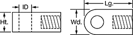
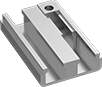
With a metal base plate for added strength, these bumpers withstand repeated impacts for a longer service life than all-rubber bumpers. You can also use them as spacers and noise reducers. Twist them onto a threaded stud on your equipment, or pair them with your own stud to create a custom-length bumper.
Multipurpose Neoprene%20--%3e%3csvg%20version='1.1'%20id='Layer_1'%20xmlns='http://www.w3.org/2000/svg'%20xmlns:xlink='http://www.w3.org/1999/xlink'%20x='0px'%20y='0px'%20viewBox='0%200%20400%20400'%20style='enable-background:new%200%200%20400%20400;'%20xml:space='preserve'%3e%3cstyle%20type='text/css'%3e%20.st0{fill:%231A70A0;}%20.st1{opacity:0.5;}%20%3c/style%3e%3cg%3e%3cg%3e%3cpath%20class='st0'%20d='M200,56.9c38.35,0,74.4,14.93,101.51,42.05c27.11,27.11,42.05,63.17,42.05,101.51s-14.93,74.4-42.05,101.51%20S238.35,344.02,200,344.02s-74.4-14.93-101.51-42.05c-27.11-27.11-42.05-63.17-42.05-101.51s14.93-74.4,42.05-101.51%20S161.65,56.9,200,56.9%20M200,12.9C96.41,12.9,12.44,96.88,12.44,200.46c0,103.59,83.97,187.56,187.56,187.56%20c103.59,0,187.56-83.97,187.56-187.56C387.56,96.88,303.59,12.9,200,12.9L200,12.9z'/%3e%3c/g%3e%3cg%3e%3cg%20class='st1'%3e%3cpath%20class='st0'%20d='M235.49,152.24h16.15l-27.46,111.87c-1.94,7.8-2.91,12.5-2.91,14.1c0,1.82,0.58,3.29,1.73,4.41%20c1.16,1.12,2.69,1.68,4.61,1.68c5.23,0,11.78-3.85,19.63-11.55l17.22,21.34c-16.95,17.33-34.87,26-53.78,26%20c-8.37,0-15.45-1.47-21.23-4.41c-5.79-2.94-10.44-7.25-13.95-12.92c-3.51-5.67-5.27-11.18-5.27-16.53c0-1.93,0.35-5.24,1.05-9.94%20c1-6.94,2.05-12.54,3.15-16.82l15.22-62.15h-32.69l7.65-30.97C190.89,163.58,214.53,158.88,235.49,152.24z%20M230.44,80.84%20c8.24,0,14.66,2.62,19.26,7.86c4.6,5.24,6.9,11.55,6.9,18.94c0,5.46-1.42,10.7-4.25,15.73c-2.83,5.03-6.88,9.07-12.12,12.12%20c-5.24,3.05-10.33,4.57-15.24,4.57c-4.6,0-9.17-1.23-13.72-3.69c-4.55-2.46-8.02-5.78-10.43-9.95%20c-2.41-4.17-3.61-8.67-3.61-13.48c0-5.35,1.52-10.64,4.57-15.89c3.05-5.24,7.03-9.25,11.96-12.04%20C218.68,82.23,224.24,80.84,230.44,80.84z'/%3e%3c/g%3e%3cg%3e%3cpath%20class='st0'%20d='M214.08,152.24h16.15l-27.46,111.87c-1.94,7.8-2.91,12.5-2.91,14.1c0,1.82,0.58,3.29,1.73,4.41%20c1.16,1.12,2.69,1.68,4.61,1.68c5.23,0,11.78-3.85,19.63-11.55l17.22,21.34c-16.95,17.33-34.87,26-53.78,26%20c-8.37,0-15.45-1.47-21.23-4.41c-5.79-2.94-10.44-7.25-13.95-12.92c-3.51-5.67-5.27-11.18-5.27-16.53c0-1.93,0.35-5.24,1.05-9.94%20c1-6.94,2.05-12.54,3.15-16.82l15.22-62.15h-32.69l7.65-30.97C169.48,163.58,193.11,158.88,214.08,152.24z%20M209.03,80.84%20c8.24,0,14.66,2.62,19.26,7.86c4.6,5.24,6.9,11.55,6.9,18.94c0,5.46-1.42,10.7-4.25,15.73c-2.83,5.03-6.88,9.07-12.12,12.12%20c-5.24,3.05-10.33,4.57-15.24,4.57c-4.6,0-9.17-1.23-13.72-3.69c-4.55-2.46-8.02-5.78-10.43-9.95%20c-2.41-4.17-3.61-8.67-3.61-13.48c0-5.35,1.52-10.64,4.57-15.89c3.05-5.24,7.03-9.25,11.96-12.04%20C197.26,82.23,202.83,80.84,209.03,80.84z'/%3e%3c/g%3e%3c/g%3e%3c/g%3e%3c/svg%3e)
|
Style 1 |
A good choice for oily equipment that's exposed to sunlight, rain, and ozone. These aren't as oil resistant as Buna-N bumpers, but they can be used outdoors.
Hardness Rating—The harder the bumper, the better it withstands impact and abrasion over time. The softer the bumper, the more cushioning it provides for objects made of glass, soft metal, and other fragile materials. Bumpers with a medium rating offer a balance of impact resistance and cushioning.
Abrasion-Resistant Polyurethane Rubber
|
Style 1 |
Our toughest rubber bumpers, they keep their shape even when knocked and scraped by metal and other abrasive materials. They're often used on industrial vehicles, conveyors, and heavy construction equipment.
Hardness Rating—The harder the bumper, the better it withstands impact and abrasion over time. The softer the bumper, the more cushioning it provides for objects made of glass, soft metal, and other fragile materials. Bumpers with a medium rating offer a balance of impact resistance and cushioning.
Thread | |||||||||||||||||||||||||||||||||||||||||||||||||||||||||||||||||||||||||||||||||||||||||||||||||||
|---|---|---|---|---|---|---|---|---|---|---|---|---|---|---|---|---|---|---|---|---|---|---|---|---|---|---|---|---|---|---|---|---|---|---|---|---|---|---|---|---|---|---|---|---|---|---|---|---|---|---|---|---|---|---|---|---|---|---|---|---|---|---|---|---|---|---|---|---|---|---|---|---|---|---|---|---|---|---|---|---|---|---|---|---|---|---|---|---|---|---|---|---|---|---|---|---|---|---|---|
Size | Dp. | OD | Ht. | Hardness | Hardness Rating | Color | Temp., ° F | Base Plate Material | Nonmarking | For Use Outdoors | Each | ||||||||||||||||||||||||||||||||||||||||||||||||||||||||||||||||||||||||||||||||||||||||
Style 1 | |||||||||||||||||||||||||||||||||||||||||||||||||||||||||||||||||||||||||||||||||||||||||||||||||||
| 1 1/4"-12 | 1 1/4" | 3" | 2 3/4" | Durometer 85A | Hard | Red | -40 to 200 | Steel | No | Yes | 9546K87 | 000000 | |||||||||||||||||||||||||||||||||||||||||||||||||||||||||||||||||||||||||||||||||||||||
Key-Locking Threaded Insert Assortments with Installation Tools
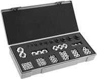 |
What you need to add or repair a range of thread sizes in soft metal, such as aluminum. These assortments include multiple key-locking inserts of each size and an installation tool. They're comparable to Keensert inserts.
Standard Wall—Stronger than thin-wall inserts, these are your go-to choice for threading most holes.
Black Phosphate-Coated Steel—These inserts resist occasional moisture.
18-8 Stainless Steel—The choice for wet and outdoor environments, these inserts resist rust and mild chemicals.
No. of Inserts Included | Includes | Thread Spacing | For Tap Thread Size | Drill Bit Size | For Max. Hole Dia. | Each | |||||||||||||||||||||||||||||||||||||||||||||||||||||||||||||||||||||||||||||||||||||||||||||
|---|---|---|---|---|---|---|---|---|---|---|---|---|---|---|---|---|---|---|---|---|---|---|---|---|---|---|---|---|---|---|---|---|---|---|---|---|---|---|---|---|---|---|---|---|---|---|---|---|---|---|---|---|---|---|---|---|---|---|---|---|---|---|---|---|---|---|---|---|---|---|---|---|---|---|---|---|---|---|---|---|---|---|---|---|---|---|---|---|---|---|---|---|---|---|---|---|---|---|---|
Standard Wall | |||||||||||||||||||||||||||||||||||||||||||||||||||||||||||||||||||||||||||||||||||||||||||||||||||
Black Phosphate-Coated Steel | |||||||||||||||||||||||||||||||||||||||||||||||||||||||||||||||||||||||||||||||||||||||||||||||||||
| 77 | 1"-12 Thread × 1 3/8" Installed Lg. (2 Each) 1/2"-20 Thread × 5/8" Installed Lg. (6 Each) 1/4"-28 Thread × 3/8" Installed Lg. (20 Each) 3/4"-16 Thread × 1 1/8" Installed Lg. (3 Each) 3/8"-24 Thread × 1/2" Installed Lg. (10 Each) 5/16"-24 Thread × 0.438" Installed Lg. (15 Each) 5/8"-18 Thread × 7/8" Installed Lg. (3 Each) 7/16"-20 Thread × 5/8" Installed Lg. (10 Each) 7/8"-14 Thread × 1 1/4" Installed Lg. (3 Each) 9/16"-18 Thread × 0.813" Installed Lg. (5 Each) Installation Tool | Fine | 7/16"-14 1/2"-13 9/16"-12 5/8"-11 3/4"-16 7/8"-14 1 1/8"-12 1 1/4"-12 1 3/8"-12 | 29/64" 33/64" 37/64" 45/64" 53/64" 1 1/16" 1 3/16" 1 5/16" X | 0.397" 0.453" 0.516" 0.578" 0.703" 0.828" 1.063" 1.186" 1.313" | 90284A215 | 0000000 | ||||||||||||||||||||||||||||||||||||||||||||||||||||||||||||||||||||||||||||||||||||||||||||
| 77 | 1"-8 Thread × 1 3/8" Installed Lg. (2 Each) 1/2"-13 Thread × 5/8" Installed Lg. (6 Each) 1/4"-20 Thread × 3/8" Installed Lg. (20 Each) 3/4"-10 Thread × 1 1/8" Installed Lg. (3 Each) 3/8"-16 Thread × 1/2" Installed Lg. (10 Each) 5/16"-18 Thread × 0.438" Installed Lg. (15 Each) 5/8"-11 Thread × 7/8" Installed Lg. (3 Each) 7/16"-14 Thread × 5/8" Installed Lg. (10 Each) 7/8"-9 Thread × 1 1/4" Installed Lg. (3 Each) 9/16"-12 Thread × 0.813" Installed Lg. (5 Each) Installation Tool | Coarse | 7/16"-14 1/2"-13 9/16"-12 5/8"-11 3/4"-16 7/8"-14 1 1/8"-12 1 1/4"-12 1 3/8"-12 | 29/64" 33/64" 37/64" 45/64" 53/64" 1 1/16" 1 3/16" 1 5/16" X | 0.397" 0.453" 0.516" 0.578" 0.703" 0.828" 1.063" 1.186" 1.313" | 90284A211 | 000000 | ||||||||||||||||||||||||||||||||||||||||||||||||||||||||||||||||||||||||||||||||||||||||||||
18-8 Stainless Steel | |||||||||||||||||||||||||||||||||||||||||||||||||||||||||||||||||||||||||||||||||||||||||||||||||||
| 77 | 1"-12 Thread × 1 3/8" Installed Lg. (2 Each) 1/2"-20 Thread × 5/8" Installed Lg. (6 Each) 1/4"-28 Thread × 3/8" Installed Lg. (20 Each) 3/4"-16 Thread × 1 1/8" Installed Lg. (3 Each) 3/8"-24 Thread × 1/2" Installed Lg. (10 Each) 5/16"-24 Thread × 0.438" Installed Lg. (15 Each) 5/8"-18 Thread × 7/8" Installed Lg. (3 Each) 7/16"-20 Thread × 5/8" Installed Lg. (10 Each) 7/8"-14 Thread × 1 1/4" Installed Lg. (3 Each) 9/16"-18 Thread × 0.813" Installed Lg. (5 Each) Installation Tool | Fine | 7/16"-14 1/2"-13 9/16"-12 5/8"-11 3/4"-16 7/8"-14 1 1/8"-12 1 1/4"-12 1 3/8"-12 | 29/64" 33/64" 37/64" 45/64" 53/64" 1 1/16" 1 3/16" 1 5/16" X | 0.397" 0.453" 0.516" 0.578" 0.703" 0.828" 1.063" 1.186" 1.313" | 90284A415 | 000000 | ||||||||||||||||||||||||||||||||||||||||||||||||||||||||||||||||||||||||||||||||||||||||||||
| 77 | 1"-8 Thread × 1 3/8" Installed Lg. (2 Each) 1/2"-13 Thread × 5/8" Installed Lg. (6 Each) 1/4"-20 Thread × 3/8" Installed Lg. (20 Each) 3/4"-10 Thread × 1 1/8" Installed Lg. (3 Each) 3/8"-16 Thread × 1/2" Installed Lg. (10 Each) 5/16"-18 Thread × 0.438" Installed Lg. (15 Each) 5/8"-11 Thread × 7/8" Installed Lg. (3 Each) 7/16"-14 Thread × 5/8" Installed Lg. (10 Each) 7/8"-9 Thread × 1 1/4" Installed Lg. (3 Each) 9/16"-12 Thread × 0.813" Installed Lg. (5 Each) Installation Tool | Coarse | 7/16"-14 1/2"-13 9/16"-12 5/8"-11 3/4"-16 7/8"-14 1 1/8"-12 1 1/4"-12 1 3/8"-12 | 29/64" 33/64" 37/64" 45/64" 53/64" 1 1/16" 1 3/16" 1 5/16" X | 0.397" 0.453" 0.516" 0.578" 0.703" 0.828" 1.063" 1.186" 1.313" | 90284A411 | 000000 | ||||||||||||||||||||||||||||||||||||||||||||||||||||||||||||||||||||||||||||||||||||||||||||
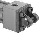
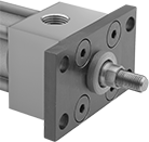
Sensor-Ready Hydraulic Cylinders
| | |
Clevis Brackets with Clevis Pin | Front/Rear Flange | Clevis Rod Ends |
| |
Clevis Pin | Hydraulic Cylinder |
|  |
Pivot Bracket |
Rod | O'all | Mounting Hole | Inlet/Outlet Connection | ||||||||||||||||||||||||||||||||||||||||||||||||||||||||||||||||||||||||||||||||||||||||||||||||
|---|---|---|---|---|---|---|---|---|---|---|---|---|---|---|---|---|---|---|---|---|---|---|---|---|---|---|---|---|---|---|---|---|---|---|---|---|---|---|---|---|---|---|---|---|---|---|---|---|---|---|---|---|---|---|---|---|---|---|---|---|---|---|---|---|---|---|---|---|---|---|---|---|---|---|---|---|---|---|---|---|---|---|---|---|---|---|---|---|---|---|---|---|---|---|---|---|---|---|---|
Stroke Lg. | Body Lg. | Max. Push Force, lbf | Max. Pull Force, lbf | Retracted Lg. | Extended Lg. | Thread Size | Dia. | Wd. | Ht. | Ctr.-to-Ctr. | Thread Size | Pipe Size | Dash Size | Thread Type | Body Material | Max. Pressure, psi | Cylinder Cushion Type | Each | |||||||||||||||||||||||||||||||||||||||||||||||||||||||||||||||||||||||||||||||||
NFPA/JIC Heavy Duty Mounting Pattern | |||||||||||||||||||||||||||||||||||||||||||||||||||||||||||||||||||||||||||||||||||||||||||||||||||
4" Diameter Bore | |||||||||||||||||||||||||||||||||||||||||||||||||||||||||||||||||||||||||||||||||||||||||||||||||||
| 3" | 9 5/8" | 31,420 | 25,400 | 12 5/8" | 15 5/8" | 1 1/4"-12 | 1 3/4" | 5" | 5" | 3 13/16" | 5/8"-16 | 3/4 | 12 | NPT | Steel | 2,500 | None | 1499N155 | 000000000 | ||||||||||||||||||||||||||||||||||||||||||||||||||||||||||||||||||||||||||||||||
| 4" | 10 5/8" | 31,420 | 25,400 | 13 5/8" | 17 5/8" | 1 1/4"-12 | 1 3/4" | 5" | 5" | 3 13/16" | 5/8"-16 | 3/4 | 12 | NPT | Steel | 2,500 | Adjustable | 1499N156 | 00000000 | ||||||||||||||||||||||||||||||||||||||||||||||||||||||||||||||||||||||||||||||||
| 5" | 11 5/8" | 31,420 | 25,400 | 14 5/8" | 19 5/8" | 1 1/4"-12 | 1 3/4" | 5" | 5" | 3 13/16" | 5/8"-16 | 3/4 | 12 | NPT | Steel | 2,500 | Adjustable | 1499N157 | 00000000 | ||||||||||||||||||||||||||||||||||||||||||||||||||||||||||||||||||||||||||||||||
| 6" | 12 5/8" | 31,420 | 25,400 | 15 5/8" | 21 5/8" | 1 1/4"-12 | 1 3/4" | 5" | 5" | 3 13/16" | 5/8"-16 | 3/4 | 12 | NPT | Steel | 2,500 | Adjustable | 1499N158 | 00000000 | ||||||||||||||||||||||||||||||||||||||||||||||||||||||||||||||||||||||||||||||||
| 7" | 13 5/8" | 31,420 | 25,400 | 16 5/8" | 23 5/8" | 1 1/4"-12 | 1 3/4" | 5" | 5" | 3 13/16" | 5/8"-16 | 3/4 | 12 | NPT | Steel | 2,500 | Adjustable | 1499N159 | 00000000 | ||||||||||||||||||||||||||||||||||||||||||||||||||||||||||||||||||||||||||||||||
| 8" | 14 5/8" | 31,420 | 25,400 | 17 5/8" | 25 5/8" | 1 1/4"-12 | 1 3/4" | 5" | 5" | 3 13/16" | 5/8"-16 | 3/4 | 12 | NPT | Steel | 2,500 | Adjustable | 1499N161 | 00000000 | ||||||||||||||||||||||||||||||||||||||||||||||||||||||||||||||||||||||||||||||||
| 9" | 15 5/8" | 31,420 | 25,400 | 18 5/8" | 27 5/8" | 1 1/4"-12 | 1 3/4" | 5" | 5" | 3 13/16" | 5/8"-16 | 3/4 | 12 | NPT | Steel | 2,500 | Adjustable | 1499N162 | 00000000 | ||||||||||||||||||||||||||||||||||||||||||||||||||||||||||||||||||||||||||||||||
| 10" | 16 5/8" | 31,420 | 25,400 | 19 5/8" | 29 5/8" | 1 1/4"-12 | 1 3/4" | 5" | 5" | 3 13/16" | 5/8"-16 | 3/4 | 12 | NPT | Steel | 2,500 | Adjustable | 1499N163 | 00000000 | ||||||||||||||||||||||||||||||||||||||||||||||||||||||||||||||||||||||||||||||||
| 11" | 17 5/8" | 31,420 | 25,400 | 20 5/8" | 31 5/8" | 1 1/4"-12 | 1 3/4" | 5" | 5" | 3 13/16" | 5/8"-16 | 3/4 | 12 | NPT | Steel | 2,500 | Adjustable | 1499N164 | 00000000 | ||||||||||||||||||||||||||||||||||||||||||||||||||||||||||||||||||||||||||||||||
| 12" | 18 5/8" | 31,420 | 25,400 | 21 5/8" | 33 5/8" | 1 1/4"-12 | 1 3/4" | 5" | 5" | 3 13/16" | 5/8"-16 | 3/4 | 12 | NPT | Steel | 2,500 | Adjustable | 1499N165 | 00000000 | ||||||||||||||||||||||||||||||||||||||||||||||||||||||||||||||||||||||||||||||||
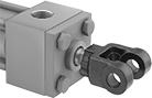
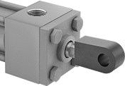
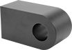
Hydraulic Cylinder Clevis Rod Ends
|  | 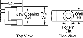 |
Clevis Rod Ends |
Overall | Shank | ||||||||||||||||||||||||||||||||||||||||||||||||||||||||||||||||||||||||||||||||||||||||||||||||||
|---|---|---|---|---|---|---|---|---|---|---|---|---|---|---|---|---|---|---|---|---|---|---|---|---|---|---|---|---|---|---|---|---|---|---|---|---|---|---|---|---|---|---|---|---|---|---|---|---|---|---|---|---|---|---|---|---|---|---|---|---|---|---|---|---|---|---|---|---|---|---|---|---|---|---|---|---|---|---|---|---|---|---|---|---|---|---|---|---|---|---|---|---|---|---|---|---|---|---|---|
For Bore Dia. | For Pin Dia. | Jaw Opening Wd. | Shank Ctr. Lg. | Wd. | Lg. | Ht. | Thread Size | Gender | Threading | For Hydraulic Cylinder Mounting Pattern | Each | ||||||||||||||||||||||||||||||||||||||||||||||||||||||||||||||||||||||||||||||||||||||||
Iron | |||||||||||||||||||||||||||||||||||||||||||||||||||||||||||||||||||||||||||||||||||||||||||||||||||
| 4" | 1 3/8" | 2 1/16" | 4 1/8" | 4 1/16" | 5 1/2" | 2 3/4" | 1 1/4"-12 | Female | Fully Threaded | NFPA Light Duty, NFPA/JIC Heavy Duty | 62205K49 | 0000000 | |||||||||||||||||||||||||||||||||||||||||||||||||||||||||||||||||||||||||||||||||||||||
Stainless Steel | |||||||||||||||||||||||||||||||||||||||||||||||||||||||||||||||||||||||||||||||||||||||||||||||||||
| — | 1 3/8" | 2 1/16" | 4 1/8" | 4 1/16" | 5 1/2" | 2 3/4" | 1 1/4"-12 | Female | Fully Threaded | NFPA Light Duty, NFPA/JIC Heavy Duty | 6043N14 | 00000000 | |||||||||||||||||||||||||||||||||||||||||||||||||||||||||||||||||||||||||||||||||||||||
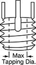
Key-Locking Threaded Inserts for Soft Metal
 |
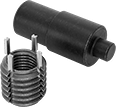
Add strong threads in soft metal, such as aluminum. The keys on these inserts drive into holes to hold more securely than thread-locking or helical inserts. They prevent slipping and rotating, so they’re stable enough for use in vehicle or aerospace parts that experience heavy vibration. These inserts are comparable to Keensert inserts.
To install, drill and tap a hole in your material. Then, thread the insert onto the installation tool and screw it into the hole. Place the tool over the keys and hit it with a hammer to drive them in.
Standard Wall—Stronger than thin-wall inserts, these are your go-to choice for threading most holes.
Extra-Thick Wall—Stronger than standard- and thin-wall inserts, use them to reduce the size of tapped holes or replace threads that have been drilled out.
Black Phosphate-Coated Steel—These inserts resist occasional moisture.
18-8 Stainless Steel—The choice for wet and outdoor environments, these inserts resist rust and mild chemicals.
Inserts | Installation Tools | Inserts with Installation Tools | |||||||||||||||||||||||||||||||||||||||||||||||||||||||||||||||||||||||||||||||||||||||||||||||||
|---|---|---|---|---|---|---|---|---|---|---|---|---|---|---|---|---|---|---|---|---|---|---|---|---|---|---|---|---|---|---|---|---|---|---|---|---|---|---|---|---|---|---|---|---|---|---|---|---|---|---|---|---|---|---|---|---|---|---|---|---|---|---|---|---|---|---|---|---|---|---|---|---|---|---|---|---|---|---|---|---|---|---|---|---|---|---|---|---|---|---|---|---|---|---|---|---|---|---|---|
Each | |||||||||||||||||||||||||||||||||||||||||||||||||||||||||||||||||||||||||||||||||||||||||||||||||||
Thread Size | For Tap Thread Size | Installed Lg. | Drill Bit Size | For Max. Hole Dia. | No. of Locking Keys | 1-9 | 10-Up | Each | No. of Inserts Included | Each | |||||||||||||||||||||||||||||||||||||||||||||||||||||||||||||||||||||||||||||||||||||||||
Standard Wall | |||||||||||||||||||||||||||||||||||||||||||||||||||||||||||||||||||||||||||||||||||||||||||||||||||
Black Phosphate-Coated Steel | |||||||||||||||||||||||||||||||||||||||||||||||||||||||||||||||||||||||||||||||||||||||||||||||||||
| 7/8"-9 | 1 1/4"-12 | 1.250" | 1 3/16" | 1.188" | 4 | 90245A041 | 000000 | 000000 | 92100A739 | 000000 | 3 | 90245A021 | 000000 | ||||||||||||||||||||||||||||||||||||||||||||||||||||||||||||||||||||||||||||||||||||||
| 7/8"-14 | 1 1/4"-12 | 1.250" | 1 3/16" | 1.188" | 4 | 90245A081 | 00000 | 00000 | 92100A739 | 00000 | 3 | 90245A061 | 00000 | ||||||||||||||||||||||||||||||||||||||||||||||||||||||||||||||||||||||||||||||||||||||
| 1 1/4"-12 | 1 5/8"-12 | 1.813" | — | 1.563" | 4 | 90245A104 | 00000 | 00000 | 92100A754 | 000000 | 2 | 90245A066 | 000000 | ||||||||||||||||||||||||||||||||||||||||||||||||||||||||||||||||||||||||||||||||||||||
18-8 Stainless Steel | |||||||||||||||||||||||||||||||||||||||||||||||||||||||||||||||||||||||||||||||||||||||||||||||||||
| 7/8"-9 | 1 1/4"-12 | 1.250" | 1 3/16" | 1.188" | 4 | 91731A074 | 00000 | 00000 | 92100A739 | 00000 | 3 | 91731A038 | 000000 | ||||||||||||||||||||||||||||||||||||||||||||||||||||||||||||||||||||||||||||||||||||||
| 7/8"-14 | 1 1/4"-12 | 1.250" | 1 3/16" | 1.188" | 4 | 91731A079 | 00000 | 00000 | 92100A739 | 00000 | — | ——— | 0 | ||||||||||||||||||||||||||||||||||||||||||||||||||||||||||||||||||||||||||||||||||||||
Extra-Thick Wall | |||||||||||||||||||||||||||||||||||||||||||||||||||||||||||||||||||||||||||||||||||||||||||||||||||
Black Phosphate-Coated Steel | |||||||||||||||||||||||||||||||||||||||||||||||||||||||||||||||||||||||||||||||||||||||||||||||||||
| 3/4"-10 | 1 1/4"-12 | 1.125" | 1 3/16" | 1.188" | 4 | 93302A180 | 00000 | 00000 | 93302A280 | 00000 | 3 | 93302A460 | 000000 | ||||||||||||||||||||||||||||||||||||||||||||||||||||||||||||||||||||||||||||||||||||||
| 3/4"-16 | 1 1/4"-12 | 1.125" | 1 3/16" | 1.188" | 4 | 93302A620 | 00000 | 00000 | 93302A280 | 00000 | — | ——— | 0 | ||||||||||||||||||||||||||||||||||||||||||||||||||||||||||||||||||||||||||||||||||||||
18-8 Stainless Steel | |||||||||||||||||||||||||||||||||||||||||||||||||||||||||||||||||||||||||||||||||||||||||||||||||||
| 3/4"-10 | 1 1/4"-12 | 1.125" | 1 3/16" | 1.188" | 4 | 93340A831 | 000000 | 00000 | 93302A280 | 00000 | — | ——— | 0 | ||||||||||||||||||||||||||||||||||||||||||||||||||||||||||||||||||||||||||||||||||||||
| 3/4"-16 | 1 1/4"-12 | 1.125" | 1 3/16" | 1.188" | 4 | 93340A832 | 00000 | 00000 | 93302A280 | 00000 | — | ——— | 0 | ||||||||||||||||||||||||||||||||||||||||||||||||||||||||||||||||||||||||||||||||||||||
Hydraulic Cylinder Flat-Shoulder Rod Ends
 |  |  |
Rod End Installed on Hydraulic Cylinder |
For Bore Dia. | ID | Thread Size | Lg. | Wd. | Ht. | Gender | For Hydraulic Cylinder Mounting Pattern | Each | |||||||||||||||||||||||||||||||||||||||||||||||||||||||||||||||||||||||||||||||||||||||||||
|---|---|---|---|---|---|---|---|---|---|---|---|---|---|---|---|---|---|---|---|---|---|---|---|---|---|---|---|---|---|---|---|---|---|---|---|---|---|---|---|---|---|---|---|---|---|---|---|---|---|---|---|---|---|---|---|---|---|---|---|---|---|---|---|---|---|---|---|---|---|---|---|---|---|---|---|---|---|---|---|---|---|---|---|---|---|---|---|---|---|---|---|---|---|---|---|---|---|---|---|
Steel | |||||||||||||||||||||||||||||||||||||||||||||||||||||||||||||||||||||||||||||||||||||||||||||||||||
| 1 1/4" | 1 3/8" | 1 1/4"-12 | 4 13/16" | 2 3/4" | 2" | Female | NFPA Light Duty, NFPA/JIC Heavy Duty | 6466N14 | 000000 | ||||||||||||||||||||||||||||||||||||||||||||||||||||||||||||||||||||||||||||||||||||||||||
Key-Locking Threaded Inserts with Installation Tools
 |
Paired with the right tool for installation, these inserts create strong threads in soft metal, such as aluminum. They have keys that drive into material to prevent inserts from slipping and rotating in the hole.
Standard Wall—Stronger than thin-wall inserts, these are your go-to choice for threading most holes.
Extra-Thick Wall—Stronger than standard- and thin-wall inserts, use them to reduce the size of tapped holes or replace threads that have been drilled out.
Black Phosphate-Coated Steel—These inserts resist occasional moisture.
18-8 Stainless Steel—The choice for wet and outdoor environments, these inserts resist rust and mild chemicals.
Thread Size | For Tap Thread Size | Installed Lg. | Drill Bit Size | For Max. Hole Dia. | No. of Locking Keys | No. of Inserts Included | Each | ||||||||||||||||||||||||||||||||||||||||||||||||||||||||||||||||||||||||||||||||||||||||||||
|---|---|---|---|---|---|---|---|---|---|---|---|---|---|---|---|---|---|---|---|---|---|---|---|---|---|---|---|---|---|---|---|---|---|---|---|---|---|---|---|---|---|---|---|---|---|---|---|---|---|---|---|---|---|---|---|---|---|---|---|---|---|---|---|---|---|---|---|---|---|---|---|---|---|---|---|---|---|---|---|---|---|---|---|---|---|---|---|---|---|---|---|---|---|---|---|---|---|---|---|
Standard Wall | |||||||||||||||||||||||||||||||||||||||||||||||||||||||||||||||||||||||||||||||||||||||||||||||||||
Black Phosphate-Coated Steel | |||||||||||||||||||||||||||||||||||||||||||||||||||||||||||||||||||||||||||||||||||||||||||||||||||
| 7/8"-9 | 1 1/4"-12 | 1.250" | 1 3/16" | 1.188" | 4 | 3 | 90245A021 | 000000 | |||||||||||||||||||||||||||||||||||||||||||||||||||||||||||||||||||||||||||||||||||||||||||
| 7/8"-14 | 1 1/4"-12 | 1.250" | 1 3/16" | 1.188" | 4 | 3 | 90245A061 | 00000 | |||||||||||||||||||||||||||||||||||||||||||||||||||||||||||||||||||||||||||||||||||||||||||
| 1 1/4"-12 | 1 5/8"-12 | 1.813" | — | 1.563" | 4 | 2 | 90245A066 | 000000 | |||||||||||||||||||||||||||||||||||||||||||||||||||||||||||||||||||||||||||||||||||||||||||
18-8 Stainless Steel | |||||||||||||||||||||||||||||||||||||||||||||||||||||||||||||||||||||||||||||||||||||||||||||||||||
| 7/8"-9 | 1 1/4"-12 | 1.250" | 1 3/16" | 1.188" | 4 | 3 | 91731A038 | 000000 | |||||||||||||||||||||||||||||||||||||||||||||||||||||||||||||||||||||||||||||||||||||||||||
Extra-Thick Wall | |||||||||||||||||||||||||||||||||||||||||||||||||||||||||||||||||||||||||||||||||||||||||||||||||||
Black Phosphate-Coated Steel | |||||||||||||||||||||||||||||||||||||||||||||||||||||||||||||||||||||||||||||||||||||||||||||||||||
| 3/4"-10 | 1 1/4"-12 | 1.125" | 1 3/16" | 1.188" | 4 | 3 | 93302A460 | 000000 | |||||||||||||||||||||||||||||||||||||||||||||||||||||||||||||||||||||||||||||||||||||||||||
Tube End Weld Nuts


Mil.-Spec. Key-Locking Threaded Inserts For Soft Metal
 |
Inserts | Installation Tools | ||||||||||||||||||||||||||||||||||||||||||||||||||||||||||||||||||||||||||||||||||||||||||||||||||
|---|---|---|---|---|---|---|---|---|---|---|---|---|---|---|---|---|---|---|---|---|---|---|---|---|---|---|---|---|---|---|---|---|---|---|---|---|---|---|---|---|---|---|---|---|---|---|---|---|---|---|---|---|---|---|---|---|---|---|---|---|---|---|---|---|---|---|---|---|---|---|---|---|---|---|---|---|---|---|---|---|---|---|---|---|---|---|---|---|---|---|---|---|---|---|---|---|---|---|---|
Thread Size | For Tap Thread Size | Installed Lg. | Drill Bit Size | For Max. Hole Dia. | No. of Locking Keys | Specs. Met | Each | Each | |||||||||||||||||||||||||||||||||||||||||||||||||||||||||||||||||||||||||||||||||||||||||||
Standard Wall | |||||||||||||||||||||||||||||||||||||||||||||||||||||||||||||||||||||||||||||||||||||||||||||||||||
High-Strength Cadmium-Plated Alloy Steel | |||||||||||||||||||||||||||||||||||||||||||||||||||||||||||||||||||||||||||||||||||||||||||||||||||
| 7/8"-9 | 1 1/4"-12 | 1.250" | 1 3/16" | 1.187" | 4 | MS51831A110 | 95101A138 | 000000 | 93904A751 | 0000000 | |||||||||||||||||||||||||||||||||||||||||||||||||||||||||||||||||||||||||||||||||||||||||
18-8 Stainless Steel | |||||||||||||||||||||||||||||||||||||||||||||||||||||||||||||||||||||||||||||||||||||||||||||||||||
| 7/8"-9 | 1 1/4"-12 | 1.250" | 1 3/16" | 1.192" | 4 | MS51831-110 | 93904A247 | 00000 | 93904A751 | 000000 | |||||||||||||||||||||||||||||||||||||||||||||||||||||||||||||||||||||||||||||||||||||||||
| 7/8"-14 | 1 1/4"-12 | 1.250" | 1 3/16" | 1.192" | 4 | MS51831-210 | 93904A249 | 00000 | ——— | 0 | |||||||||||||||||||||||||||||||||||||||||||||||||||||||||||||||||||||||||||||||||||||||||
Extra-Thick Wall | |||||||||||||||||||||||||||||||||||||||||||||||||||||||||||||||||||||||||||||||||||||||||||||||||||
18-8 Stainless Steel | |||||||||||||||||||||||||||||||||||||||||||||||||||||||||||||||||||||||||||||||||||||||||||||||||||
| 3/4"-10 | 1 1/4"-12 | 1.125" | 1 3/16" | 1.192" | 4 | MS51832-109 | 93904A243 | 00000 | 93904A773 | 00000 | |||||||||||||||||||||||||||||||||||||||||||||||||||||||||||||||||||||||||||||||||||||||||
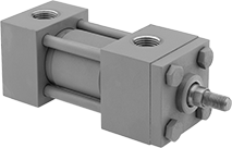
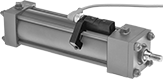
Compact Hydraulic Cylinders
 |
 |
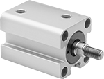
With a small body size, these cylinders fit into tight spaces but offer similar push forces to standard hydraulic cylinders. They’re double-acting cylinders, so they have two hydraulic ports—one to extend the piston rod and another to retract it. No matter the direction they’re moving, they can operate at nearly full force. This allows them to both push and pull multi-ton loads. All have a magnetic piston and can be used with sensors (sold separately) that electronically indicate piston position. Mount sensors to the cylinder with mounting brackets (sold separately).
Rod | O'all | Mounting Hole | Inlet/Outlet Connection | ||||||||||||||||||||||||||||||||||||||||||||||||||||||||||||||||||||||||||||||||||||||||||||||||
|---|---|---|---|---|---|---|---|---|---|---|---|---|---|---|---|---|---|---|---|---|---|---|---|---|---|---|---|---|---|---|---|---|---|---|---|---|---|---|---|---|---|---|---|---|---|---|---|---|---|---|---|---|---|---|---|---|---|---|---|---|---|---|---|---|---|---|---|---|---|---|---|---|---|---|---|---|---|---|---|---|---|---|---|---|---|---|---|---|---|---|---|---|---|---|---|---|---|---|---|
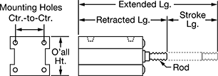
Stroke Lg. | Body Lg. | Max. Push Force, lbf | Max. Pull Force, lbf | Retracted Lg. | Extended Lg. | Thread Size | Dia. | Wd. | Ht. | Ctr.-to-Ctr. | Dia. | Pipe Size | Dash Size | Thread Type | Body Material | Max. Pressure, psi | Cylinder Cushion Type | Each | |||||||||||||||||||||||||||||||||||||||||||||||||||||||||||||||||||||||||||||||||
3" Diameter Bore | |||||||||||||||||||||||||||||||||||||||||||||||||||||||||||||||||||||||||||||||||||||||||||||||||||
| 3" | 6 1/2" | 18,070 | 12,350 | 8 15/16" | 11 7/8" | 1 1/4"-12 | 1 3/4" | 4 3/4" | 4 3/4" | 3 3/8" | 19/32" | 3/8 | 06 | NPT | Aluminum | 2,300 | None | 1304K117 | 0000000 | ||||||||||||||||||||||||||||||||||||||||||||||||||||||||||||||||||||||||||||||||
| 4" | 7 1/2" | 18,070 | 12,350 | 9 15/16" | 13 7/8" | 1 1/4"-12 | 1 3/4" | 4 3/4" | 4 3/4" | 3 3/8" | 19/32" | 3/8 | 06 | NPT | Aluminum | 2,300 | None | 1304K118 | 000000 | ||||||||||||||||||||||||||||||||||||||||||||||||||||||||||||||||||||||||||||||||
AC Voltage, V AC | DC Voltage, V DC | Solid State Output | With Switch Component | Each | |||||||||||||||||||||||||||||||||||||||||||||||||||||||||||||||||||||||||||||||||||||||||||||||
|---|---|---|---|---|---|---|---|---|---|---|---|---|---|---|---|---|---|---|---|---|---|---|---|---|---|---|---|---|---|---|---|---|---|---|---|---|---|---|---|---|---|---|---|---|---|---|---|---|---|---|---|---|---|---|---|---|---|---|---|---|---|---|---|---|---|---|---|---|---|---|---|---|---|---|---|---|---|---|---|---|---|---|---|---|---|---|---|---|---|---|---|---|---|---|---|---|---|---|---|
Reed Switch—For 1", 1 1/4", 1 1/2", 2", 2 1/2", 3", and 4" Bore Dia. | |||||||||||||||||||||||||||||||||||||||||||||||||||||||||||||||||||||||||||||||||||||||||||||||||||
| 24, 48, 100 | 24, 48, 100 | — | — | 62245K91 | 000000 | ||||||||||||||||||||||||||||||||||||||||||||||||||||||||||||||||||||||||||||||||||||||||||||||
| — | 24, 100 | — | LED | 62245K92 | 00000 | ||||||||||||||||||||||||||||||||||||||||||||||||||||||||||||||||||||||||||||||||||||||||||||||
Solid-State Switch—For 1", 1 1/4", 1 1/2", 2", 2 1/2", 3", and 4" Bore Dia. | |||||||||||||||||||||||||||||||||||||||||||||||||||||||||||||||||||||||||||||||||||||||||||||||||||
| — | 24 | NPN | LED | 62245K94 | 00000 | ||||||||||||||||||||||||||||||||||||||||||||||||||||||||||||||||||||||||||||||||||||||||||||||
| — | 24 | PNP | LED | 62245K95 | 00000 | ||||||||||||||||||||||||||||||||||||||||||||||||||||||||||||||||||||||||||||||||||||||||||||||
 |
For Bore Dia. | For Sensor Type | Material | Includes | Each | ||
|---|---|---|---|---|---|---|
| 1 1/2", 2", 2 1/2", 3", 4" | Reed Switch, Solid-State Switch | Zinc Alloy | Set Screw | 1304K54 | 00000 |
Left-Hand-Thread Tube End Weld Nuts


Screw-Locking Seize-Resistant Key-Locking Threaded Inserts for Soft Metal
 |
Create the tightest hold in aluminum and other soft metal without screws sticking. The lubricant on these inserts eases installation, and the irregularly shaped threads won’t let screws back out from vibration. Inserts have keys that drive into material to prevent them from slipping or rotating in the hole.
To install, drill and tap a hole in your material. Then, thread the insert onto the installation tool and screw it into the hole. Place the tool over the keys and hit it with a hammer to drive them in.
Standard Wall—Stronger than thin-wall inserts, these are your go-to choice for threading most holes.
Dry-Film-Lubricated 18-8 Stainless Steel—The choice for wet and outdoor environments, these inserts resist rust and mild chemicals.
Inserts | Installation Tools | ||||||||||||||||||||||||||||||||||||||||||||||||||||||||||||||||||||||||||||||||||||||||||||||||||
|---|---|---|---|---|---|---|---|---|---|---|---|---|---|---|---|---|---|---|---|---|---|---|---|---|---|---|---|---|---|---|---|---|---|---|---|---|---|---|---|---|---|---|---|---|---|---|---|---|---|---|---|---|---|---|---|---|---|---|---|---|---|---|---|---|---|---|---|---|---|---|---|---|---|---|---|---|---|---|---|---|---|---|---|---|---|---|---|---|---|---|---|---|---|---|---|---|---|---|---|
Thread Size | For Tap Thread Size | Installed Lg. | Drill Bit Size | For Max. Hole Dia. | No. of Locking Keys | Specs. Met | Each | Each | |||||||||||||||||||||||||||||||||||||||||||||||||||||||||||||||||||||||||||||||||||||||||||
Standard Wall | |||||||||||||||||||||||||||||||||||||||||||||||||||||||||||||||||||||||||||||||||||||||||||||||||||
Dry-Film-Lubricated 18-8 Stainless Steel | |||||||||||||||||||||||||||||||||||||||||||||||||||||||||||||||||||||||||||||||||||||||||||||||||||
| 7/8"-9 | 1 1/4"-12 | 1.375" | 1 3/16" | 1.188" | 4 | MS51831-110L | 97255A151 | 000000 | 93904A751 | 0000000 | |||||||||||||||||||||||||||||||||||||||||||||||||||||||||||||||||||||||||||||||||||||||||
| 7/8"-14 | 1 1/4"-12 | 1.375" | 1 3/16" | 1.188" | 4 | MS51831-210L | 97255A152 | 00000 | ——— | 0 | |||||||||||||||||||||||||||||||||||||||||||||||||||||||||||||||||||||||||||||||||||||||||
Helical Threaded Inserts
 |
Pronged |
Restore, reinforce, or create threads in metal. The tough coils on these inserts expand once installed to anchor in a tapped hole. Also known as Heli-Coil inserts, they're often used in engine heads and machinery housings where strong connections are critical. Unlike threadlocking inserts, you can remove and reuse them without them losing their strength.
Installation requires a drill bit, a helical insert tap, and an installation tool.
Pronged—The prong attaches to an installation tool for precise control as you drive inserts in. Remove the prong with a punch or break-off tool before inserting a screw.
18-8 Stainless Steel—The choice for wet and outdoor environments, these inserts resist rust and mild chemicals.
Inserts | Through-Hole Taps | Closed-End Hole Taps | Installation Tools | Inserts with Installation Tools | |||||||||||||||||||||||||||||||||||||||||||||||||||||||||||||||||||||||||||||||||||||||||||||||
|---|---|---|---|---|---|---|---|---|---|---|---|---|---|---|---|---|---|---|---|---|---|---|---|---|---|---|---|---|---|---|---|---|---|---|---|---|---|---|---|---|---|---|---|---|---|---|---|---|---|---|---|---|---|---|---|---|---|---|---|---|---|---|---|---|---|---|---|---|---|---|---|---|---|---|---|---|---|---|---|---|---|---|---|---|---|---|---|---|---|---|---|---|---|---|---|---|---|---|---|
Thread Size | Installed Lg. | Drill Bit Size | For Max. Hole Dia. | Specs. Met | Pkg. Qty. | Pkg. | Each | Each | Each | No. of Inserts Included | Each | ||||||||||||||||||||||||||||||||||||||||||||||||||||||||||||||||||||||||||||||||||||||||
Pronged | |||||||||||||||||||||||||||||||||||||||||||||||||||||||||||||||||||||||||||||||||||||||||||||||||||
18-8 Stainless Steel | |||||||||||||||||||||||||||||||||||||||||||||||||||||||||||||||||||||||||||||||||||||||||||||||||||
| 1 1/4"-12 | 1.250" | 1 9/32" | 1.281" | MS124667 | 1 | 91732A039 | 000000 | 91709A077 | 0000000 | 91709A509 | 0000000 | 90261A167 | 0000000 | — | ——— | 0 | |||||||||||||||||||||||||||||||||||||||||||||||||||||||||||||||||||||||||||||||||||
| 1 1/4"-12 | 1.875" | 1 9/32" | 1.281" | MS124707 | 1 | 91732A041 | 00000 | 91709A077 | 000000 | 91709A509 | 000000 | 90261A167 | 000000 | 4 | 91732A129 | 0000000 | |||||||||||||||||||||||||||||||||||||||||||||||||||||||||||||||||||||||||||||||||||
Helical Threaded Inserts with Installation Tools
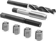 |
Drill Bit, Installation Tool and Through-Hole Tap |
Quickly restore stripped threads—these inserts come with through-hole taps and installation tools. The tough coils on these inserts expand once installed to anchor in a tapped hole.
Pronged—The prong attaches to an installation tool for precise control as you drive inserts in. Remove the prong with a punch or break-off tool before inserting a screw.
18-8 Stainless Steel—The choice for wet and outdoor environments, these inserts resist rust and mild chemicals.
Thread Size | Installed Lg. | Drill Bit Size | For Max. Hole Dia. | No. of Inserts Included | Includes | Each | |||||||||||||||||||||||||||||||||||||||||||||||||||||||||||||||||||||||||||||||||||||||||||||
|---|---|---|---|---|---|---|---|---|---|---|---|---|---|---|---|---|---|---|---|---|---|---|---|---|---|---|---|---|---|---|---|---|---|---|---|---|---|---|---|---|---|---|---|---|---|---|---|---|---|---|---|---|---|---|---|---|---|---|---|---|---|---|---|---|---|---|---|---|---|---|---|---|---|---|---|---|---|---|---|---|---|---|---|---|---|---|---|---|---|---|---|---|---|---|---|---|---|---|---|
Pronged | |||||||||||||||||||||||||||||||||||||||||||||||||||||||||||||||||||||||||||||||||||||||||||||||||||
18-8 Stainless Steel | |||||||||||||||||||||||||||||||||||||||||||||||||||||||||||||||||||||||||||||||||||||||||||||||||||
| 1 1/4"-12 | 1.875" | 1 9/32" | 1.281" | 4 | Drill Bit Installation Tool Through-Hole Tap | 91732A129 | 0000000 | ||||||||||||||||||||||||||||||||||||||||||||||||||||||||||||||||||||||||||||||||||||||||||||
Finish-Your-Own Key-Locking Threaded Inserts for Soft Metal
 |  |
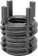
Tap the thread size you need into the solid body of these inserts. They’re a great choice when you need a custom combination of internal thread size and external diameter. Use them to repair or add new threads in soft metal, such as aluminum. They can also plug threaded holes without the hassle of welding. Keys on the inserts drive into material to prevent slipping and rotating in the hole.
To install, drill and tap a hole in your material. Then, thread the insert onto the installation tool and screw it into the hole. Place the tool over the keys and hit it with a hammer to drive them in.
Black Phosphate-Coated Steel—These inserts resist occasional moisture.
Threaded Rod Collars

