


Filter by
System of Measurement
Thread Size

Nut Type

Thread Type
Component
Material
Threaded Insert Type
Thread Direction

Hardness
Thread Spacing


Specifications Met
DFARS Specialty Metals
Export Control Classification Number (ECCN)
Metric Precision Lead Screws and Nuts
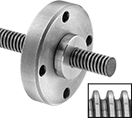 |
Pair with a motor in automated motion and positioning applications. A tight thread fit allows these lead screws and nuts to make accurate, repeatable starts and stops. Also known as single-start and self-locking lead screws and nuts, they have a single thread that runs the length of the screw. The nut travels only when the screw turns, so your system won’t unexpectedly move when the lead screw is at rest. To ensure compatibility, select components that have the same thread direction, size, and number of thread starts.
Round Nuts—Right-Hand Thread
 |
932 Bearing Bronze—932 bearing bronze and 673 bronze nuts are wear resistant. They have good machinability and fair corrosion resistance.
Travel Distance per Turn—Travel distance per turn, also known as screw lead, is the distance a nut moves with one revolution of the lead screw.
Thread Size | Lg. | Dia. | Thread Type | Speed Ratio | No. of Thread Starts | Travel Distance per Turn, mm | Thread Fit | Hardness | Tensile Strength | Dynamic Thrust Load Cap., lb. | Specs. Met | Each | |||
|---|---|---|---|---|---|---|---|---|---|---|---|---|---|---|---|
932 Bearing Bronze | |||||||||||||||
| M24 × 5 mm | 2" | 1.75" | Metric Trapezoidal | 1:1 | 1 | 5 | Metric Trapezoidal Class 7H | Brinell 70 | Not Rated | 4,500 | DIN 103 | 7549K38 | 000000 | ||
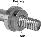
Externally Threaded Nuts—Right-Hand Thread
 |
Manganese Bronze—Manganese bronze nuts have good strength and wear resistance.
Travel Distance per Turn—Travel distance per turn, also known as screw lead, is the distance a nut moves with one revolution of the lead screw.
External Thread | |||||||||||||||||
|---|---|---|---|---|---|---|---|---|---|---|---|---|---|---|---|---|---|
Thread Size | Lg. | Dia. | Thread Type | Speed Ratio | No. of Thread Starts | Travel Distance per Turn, mm | Size | Lg. | Thread Fit | Hardness | Tensile Strength, psi | Dynamic Thrust Load Cap., lb. | Specs. Met | Each | |||
Manganese Bronze | |||||||||||||||||
| M24 × 5 mm | 1 1/2" | 1.5" | Metric Trapezoidal | 1:1 | 1 | 5 | 1 3/8"-16 | 1/2" | Metric Trapezoidal Class 7H | Brinell 126 | 75,000 | 4,500 | DIN 103 | 7549K93 | 0000000 | ||
Metric Clamping Lead Screw Collars
 |
Thread Size | OD, mm | Wd., mm | No. of Thread Starts | Hardness | Each | |||
|---|---|---|---|---|---|---|---|---|
Right-Hand Thread | ||||||||
Black-Oxide 1215 Carbon Steel | ||||||||
| M24 × 5 mm | 45 | 15 | 1 | Brinell 167 | 2198N103 | 000000 | ||
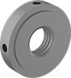
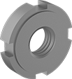
Bearing Locknuts
 |
 |
Carbon Steel |
Thread | Zinc-Plated Carbon Steel | |||||||
|---|---|---|---|---|---|---|---|---|
Size | Spacing | OD, mm | Wd., mm | Insert Max. Temp., ° F | Each | |||
Chamfered Face | ||||||||
| M24 × 1.5 mm | Extra Fine | 38 | 10.5 | 210 | 3552N31 | 000000 | ||
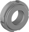
Thin-Profile Bearing Nuts
 |
 |
Thread | ||||||||
|---|---|---|---|---|---|---|---|---|
Size | Spacing | OD, mm | Wd., mm | Specs. Met | Each | |||
Carbon Steel | ||||||||
Stepped Face | ||||||||
| M24 × 1.5 mm | Extra Fine | 42 | 9 | DIN 1816 | 3549N18 | 000000 | ||
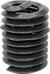
Thread-Locking Threaded Inserts
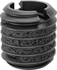 |
With Loctite® adhesive already on the threads, these inserts won’t back out or vibrate loose. The adhesive reaches full strength after 72 hours. Unlike helical inserts, you can install them with a standard drill and tap. However, thread-locking inserts are difficult to remove and reuse.
After drilling and tapping your hole, install inserts with a wrench or an installation bit. To use a wrench, thread an insert and two hex nuts onto a bolt. Then, grip and turn the top nut to drive into the hole. For slotted inserts, you can drive with a slotted screwdriver instead.
Standard Wall—Stronger than thin-wall inserts, these are your go-to choice for threading most holes.
Black Phosphate-Coated Steel—These inserts resist occasional moisture.
18-8 Stainless Steel—The choice for wet and outdoor environments, these inserts resist rust and mild chemicals.
Inserts | Installation Tools | |||||||||||
|---|---|---|---|---|---|---|---|---|---|---|---|---|
Thread Size | For Tap Thread Size | Installed Lg., mm | Drill Bit Size, mm | For Max. Hole Dia., mm | Drive Style | Pkg. Qty. | Pkg. | Each | ||||
Standard Wall | ||||||||||||
Black Phosphate-Coated Steel | ||||||||||||
| M16 x 2 mm | M24 x 3 mm | 20 | 21 | 21 | Slotted | 1 | 97084A270 | 00000 | 94110A190 | 000000 | ||
| M24 x 3 mm | M36 x 4 mm | 30 | 33 | 33 | Slotted | 1 | 97084A317 | 00000 | 94110A250 | 00000 | ||
18-8 Stainless Steel | ||||||||||||
| M16 x 2 mm | M24 x 3 mm | 20 | 21 | 21 | Slotted | 1 | 97120A270 | 0000 | 94110A190 | 00000 | ||
Helical Threaded Inserts with Installation Tools
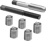 |
Installation Tool and Through-Hole Tap |
Quickly restore stripped threads—these inserts come with through-hole taps and installation tools. The tough coils on these inserts expand once installed to anchor in a tapped hole.
Pronged—The prong attaches to an installation tool for precise control as you drive inserts in. Remove the prong with a punch or break-off tool before inserting a screw.
18-8 Stainless Steel—The choice for wet and outdoor environments, these inserts resist rust and mild chemicals.
Thread Size | Installed Lg., mm | Drill Bit Size | For Max. Hole Dia. | No. of Inserts Included | Includes | Each | |||
|---|---|---|---|---|---|---|---|---|---|
Pronged | |||||||||
18-8 Stainless Steel | |||||||||
| M24 x 3 mm | 36 | 31/32" | 0.969" | 5 | Installation Tool Through-Hole Tap | 91732A969 | 0000000 | ||
Thread-Locking Threaded Insert Assortments
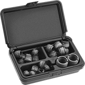 |
These assortments include various sizes of thread-locking inserts, which won’t back out or loosen from vibration. Also known as E-Z Lok, they come with Loctite® adhesive already applied, and the adhesive reaches full strength after 72 hours. After drilling and tapping your hole, install inserts with a wrench or use an installation bit (not included). To use a wrench, thread an insert and two hex nuts onto a bolt. Then, grip and turn the top nut to drive into the hole.
Standard Wall—Stronger than thin-wall inserts, these are your go-to choice for threading most holes.
Black Phosphate-Coated Steel—These inserts resist occasional moisture.
18-8 Stainless Steel—The choice for wet and outdoor environments, these inserts resist rust and mild chemicals.
For Tap | |||||||||||
|---|---|---|---|---|---|---|---|---|---|---|---|
No. of Inserts Included | Includes | Thread Spacing | Thread Size | Thread Pitch | Drill Bit Size | For Maximum Hole Diameter | Drive Style | Each | |||
Standard Wall | |||||||||||
Black Phosphate-Coated Steel | |||||||||||
| 33 | M8×1.25 mm Thread × 12.5 mm Installed Lg. (10 Each) M10×1.5 mm Thread × 17 mm Installed Lg. (10 Each) M12×1.75 mm Thread × 17 mm Installed Lg. (8 Each) M16×2 mm Thread × 20 mm Installed Lg. (5 Each) | Coarse | M12 M16 M16 M24 | 1.75 mm 2 mm 2 mm 3 mm | 10.4 mm 14 mm 14 mm 21 mm | 10.4 mm 14 mm 14 mm 21 mm | Slotted | 97084A290 | 0000000 | ||
18-8 Stainless Steel | |||||||||||
| 33 | M8×1.25 mm Thread × 12.5 mm Installed Lg. (10 Each) M10×1.5 mm Thread × 17 mm Installed Lg. (10 Each) M12×1.75 mm Thread × 17 mm Installed Lg. (8 Each) M16×2 mm Thread × 20 mm Installed Lg. (5 Each) | Coarse | M12 M16 M16 M24 | 1.75 mm 2 mm 2 mm 3 mm | 10.4 mm 14 mm 14 mm 21 mm | 10.4 mm 14 mm 14 mm 21 mm | Slotted | 97120A035 | 000000 | ||
Key-Locking Threaded Inserts with Installation Tools
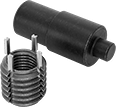 |
Paired with the right tool for installation, these inserts create strong threads in soft metal, such as aluminum. They have keys that drive into material to prevent inserts from slipping and rotating in the hole.
Standard Wall—Stronger than thin-wall inserts, these are your go-to choice for threading most holes.
Black Phosphate-Coated Steel—These inserts resist occasional moisture.
18-8 Stainless Steel—The choice for wet and outdoor environments, these inserts resist rust and mild chemicals.
Thread Size | For Tap Thread Size | Installed Lg., mm | Drill Bit Size, mm | For Max. Hole Dia., mm | No. of Locking Keys | No. of Inserts Included | Each | |||
|---|---|---|---|---|---|---|---|---|---|---|
Standard Wall | ||||||||||
Black Phosphate-Coated Steel | ||||||||||
| M18 x 1.5 mm | M24 x 1.5 mm | 24 | 22.5 | 22.5 | 4 | 2 | 90245A321 | 000000 | ||
| M24 x 3 mm | M33 x 2 mm | 33 | 31 | 31 | 4 | 2 | 90245A341 | 000000 | ||
18-8 Stainless Steel | ||||||||||
| M18 x 1.5 mm | M24 x 1.5 mm | 24 | 22.5 | 22.5 | 4 | 2 | 93715A475 | 000000 | ||
Bearing Nuts
 |
Carbon Steel Stepped Face |
Often paired with spring lock washers to strengthen their hold, these bearing nuts—also known as shaft nuts—keep vibration from shifting bearings, bushings, pulleys, and gears on your threaded shaft or spindle. They have slotted sides, so you can tighten and loosen them with a spanner wrench or spanner socket.
Carbon Steel—Carbon steel bearing nuts are strong and resist wear.
Stepped Face—Use stepped-face bearing nuts with DIN 462 spring lock washers. You can also use them in pairs or with other bearing nuts. For the nut closer to the bearing, position the stepped face towards the bearing. All meet DIN standards for bearing lockout dimensions.
Thread Spacing—When choosing your thread spacing, consider the precision of your application. The finer the threads, the more control you have when making adjustments.
Screw-Locking Seize-Resistant Key-Locking Threaded Inserts for Soft Metal
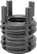 |
Create the tightest hold in aluminum and other soft metal without screws sticking. The lubricant on these inserts eases installation, and the irregularly shaped threads won’t let screws back out from vibration. Inserts have keys that drive into material to prevent them from slipping or rotating in the hole.
To install, drill and tap a hole in your material. Then, thread the insert onto the installation tool and screw it into the hole. Place the tool over the keys and hit it with a hammer to drive them in.
Standard Wall—Stronger than thin-wall inserts, these are your go-to choice for threading most holes.
Dry-Film-Lubricated Cadmium-Plated Steel—The plating creates a barrier against rust.
Screw-Locking Helical Threaded Inserts
 |
Pronged |
The irregularly shaped threads tightly grip screws to prevent them from loosening or backing out under vibration. Use these inserts to create or repair threads in pumps and other machinery that shakes and rattles. Also known as Heli-Coil inserts.
Installation requires a drill bit, a helical insert tap, and an installation tool.
Pronged—The prong attaches to an installation tool for precise control as you drive inserts in. Remove the prong with a punch or break-off tool before inserting a screw.
18-8 Stainless Steel—The choice for wet and outdoor environments, these inserts resist rust and mild chemicals.
Helical Threaded Inserts
 |
Pronged |
Restore, reinforce, or create threads in metal. The tough coils on these inserts expand once installed to anchor in a tapped hole. Also known as Heli-Coil inserts, they're often used in engine heads and machinery housings where strong connections are critical. Unlike threadlocking inserts, you can remove and reuse them without them losing their strength.
Installation requires a drill bit, a helical insert tap, and an installation tool.
Pronged—The prong attaches to an installation tool for precise control as you drive inserts in. Remove the prong with a punch or break-off tool before inserting a screw.
18-8 Stainless Steel—The choice for wet and outdoor environments, these inserts resist rust and mild chemicals.
Inserts | Through-Hole Taps | Closed-End Hole Taps | Installation Tools | Inserts with Installation Tools | ||||||||||||||
|---|---|---|---|---|---|---|---|---|---|---|---|---|---|---|---|---|---|---|
Thread Size | Installed Lg., mm | Drill Bit Size | For Max. Hole Dia. | Specs. Met | Pkg. Qty. | Pkg. | Each | Each | Each | No. of Inserts Included | Each | |||||||
Pronged | ||||||||||||||||||
18-8 Stainless Steel | ||||||||||||||||||
| M24 x 3 mm | 36 | 31/32" | 0.969" | SAE MA3279-179 | 1 | 92450A125 | 00000 | 92450A325 | 0000000 | 91709A340 | 0000000 | 92450A189 | 000000 | 5 | 91732A969 | 0000000 | ||
Key-Locking Threaded Inserts for Soft Metal
 |
Add strong threads in soft metal, such as aluminum. The keys on these inserts drive into holes to hold more securely than thread-locking or helical inserts. They prevent slipping and rotating, so they’re stable enough for use in vehicle or aerospace parts that experience heavy vibration. These inserts are comparable to Keensert inserts.
To install, drill and tap a hole in your material. Then, thread the insert onto the installation tool and screw it into the hole. Place the tool over the keys and hit it with a hammer to drive them in.
Standard Wall—Stronger than thin-wall inserts, these are your go-to choice for threading most holes.
Black Phosphate-Coated Steel—These inserts resist occasional moisture.
18-8 Stainless Steel—The choice for wet and outdoor environments, these inserts resist rust and mild chemicals.
Inserts | Installation Tools | Inserts with Installation Tools | |||||||||||||
|---|---|---|---|---|---|---|---|---|---|---|---|---|---|---|---|
Each | |||||||||||||||
Thread Size | For Tap Thread Size | Installed Lg., mm | Drill Bit Size, mm | For Max. Hole Dia., mm | No. of Locking Keys | 1-9 | 10-Up | Each | No. of Inserts Included | Each | |||||
Standard Wall | |||||||||||||||
Black Phosphate-Coated Steel | |||||||||||||||
| M18 x 1.5 mm | M24 x 1.5 mm | 24 | 22.5 | 22.5 | 4 | 90245A197 | 000000 | 000000 | 94010A350 | 000000 | 2 | 90245A321 | 000000 | ||
| M24 x 2 mm | M33 x 2 mm | 33 | 31 | 31 | 4 | 90245A217 | 00000 | 00000 | 94010A365 | 00000 | — | ——— | 0 | ||
| M24 x 3 mm | M33 x 2 mm | 33 | 31 | 31 | 4 | 90245A213 | 00000 | 00000 | 94010A365 | 00000 | 2 | 90245A341 | 000000 | ||
18-8 Stainless Steel | |||||||||||||||
| M18 x 1.5 mm | M24 x 1.5 mm | 24 | 22.5 | 22.5 | 4 | 93715A665 | 00000 | 00000 | 94010A350 | 00000 | 2 | 93715A475 | 000000 | ||
| M24 x 3 mm | M33 x 2 mm | 33 | 31 | 31 | 4 | 93715A685 | 00000 | 00000 | 94010A365 | 00000 | — | ——— | 0 | ||
